XO electronic game
Greetings, Habr!
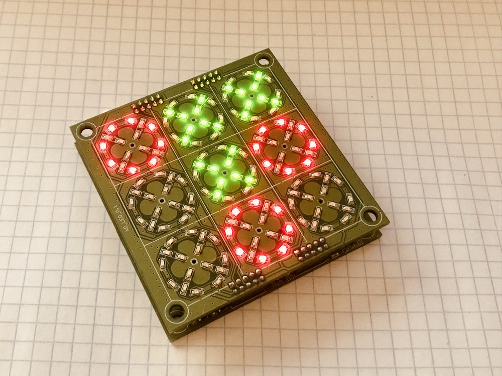
As you may have guessed from the photograph, today we are not talking about the classification of brandy. I will do the game of tic-tac-toe ... Who cares - I ask under the cat ->
The idea, as always, was born spontaneously. Once, on a quiet autumn evening, I drew nine squares on a leaf and suggested that my daughter play a new game for her. Having played several times, I saw that there was genuine interest ... and then Ostap suffered.
It would seem that it is easier to continue to draw the cells on a piece of paper or download the program to the phone, but is it interesting? Not!
What I wanted to get:
First things first.
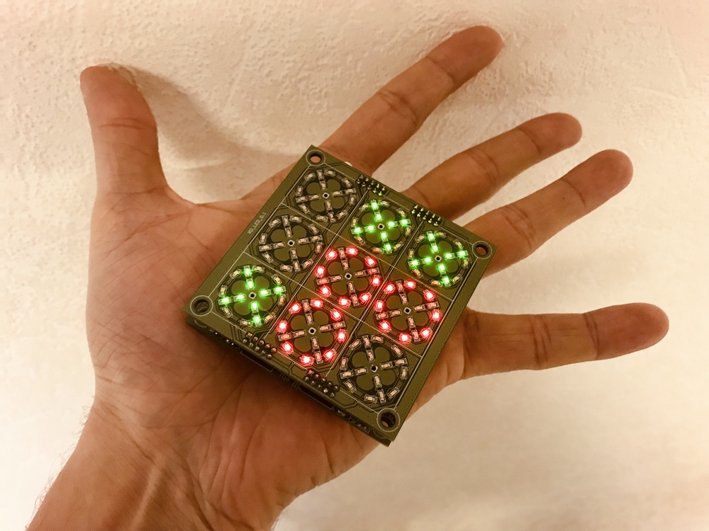
1. So, it was decided to take the controller STM32F100. On it, I can fully implement the simple logic of the game to begin with. On the case with 48 legs, all GPIOs are occupied (without the use of multiplexers and expanders). For each cross and zero, 8 LEDs (connected in parallel) are used, which are switched by field workers (IRLML6401).
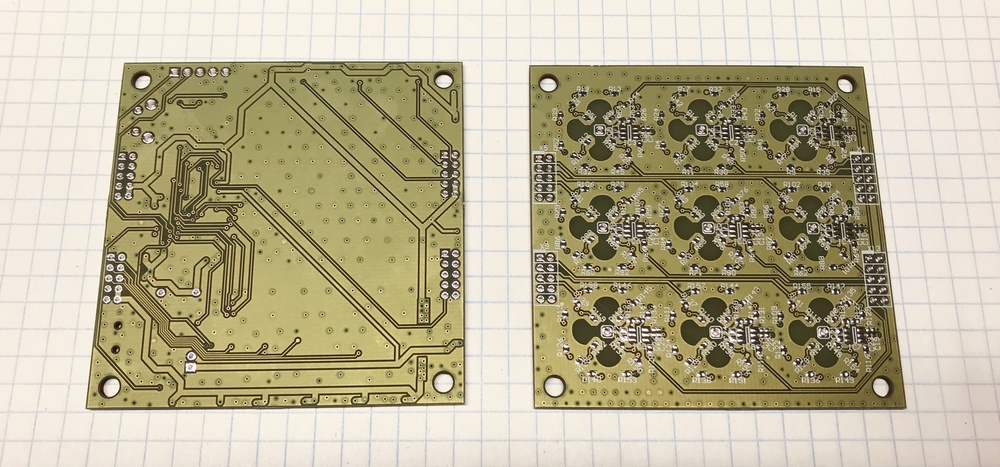
The device consists of two boards, one with LEDs and touch buttons, the second with a controller, charging, battery, etc. Connected with connectors with a pitch of 2mm, between the boards is a 1250mA battery.
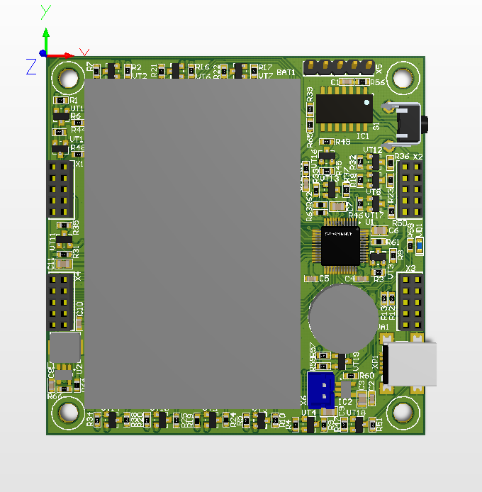
Fig. 1. The controller board
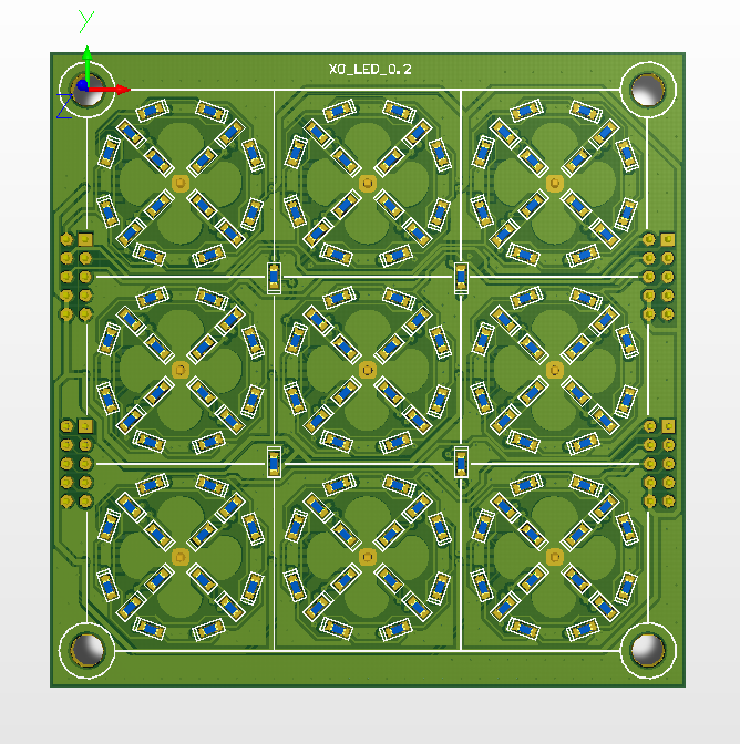
Fig. 2. Fee LEDs
A few days later the fees finally came out of production. I had the feeling that the game would be uncomfortable because of the size or the touch buttons. Looking ahead to say that playing is very cool! Buttons work fine through plexiglass 1.5-2mm.
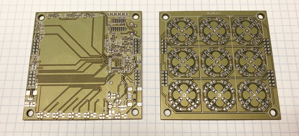
Fig. 3. TOP side of the controller board and LEDs
. 4. BOTTOM side of the controller board and LEDs
2. Charging scheme is the simplest one I poke into such devices.
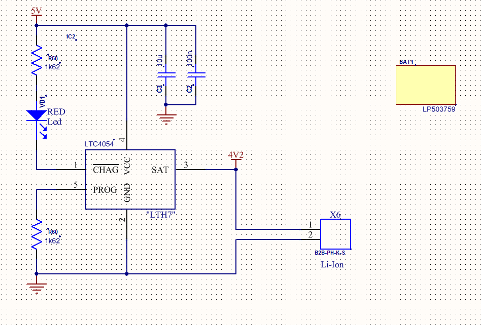
Fig. 5. Charge controller circuit.
3. Everything would be fine, but there were more components than I expected, and I was tormented by soldering. That's what happened after the soldering.
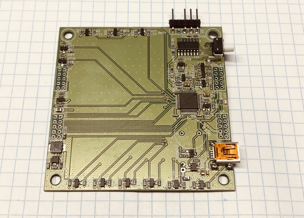
Fig. 6. The controller board with the components of
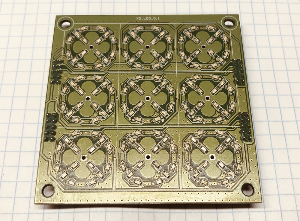
Fig. 7. LED board with components
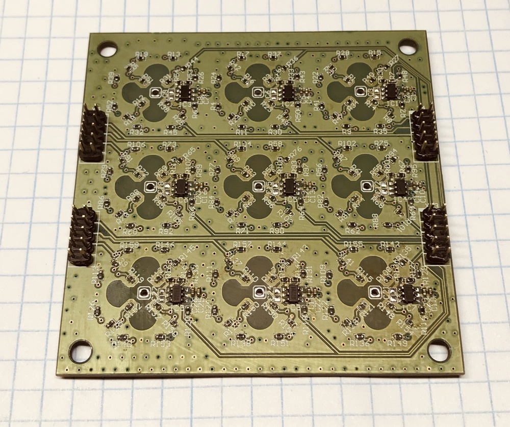
Fig. 8. LED board with components on the side of the touch buttons.
The first, and so far the only, version of the software I did on if and in one infinite loop. Simple and works without bugs. When winning, the entire field goes out and the winning combination blinks twice.
4. I decided to implement the touch buttons on the TTP223 chips, I already used them in one of my projects. They are not demanding for wiring and for the presence / absence of a polygon under the sensor.
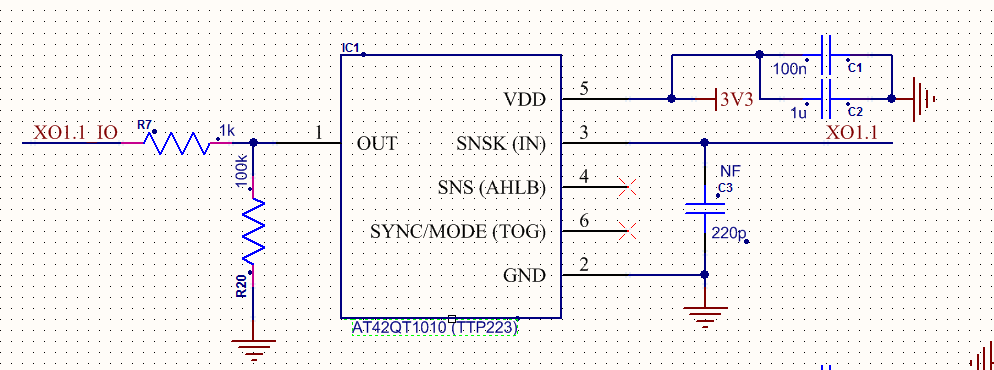
Fig. 9. The scheme of inclusion of the touch buttons.
I had more than 9pcs of them, so I decided not to use the multiplexer and hang each button on my GPIO controller.
5. Next I plan to integrate the game algorithm with the controller (I have already found several decent options). Switching for now is planned to be made by clamping the central touch button before switching on (but this is not yet final).
6. I thought for a long time how to implement on / off with one button in a simple way. The fastest and correct option, in my opinion, is on transistors and using two GPIO controllers, which I don’t have. Therefore, put the chip CD4013BM. Switching on is performed by pressing for about 1s, switching off by quick pressing. Works great.
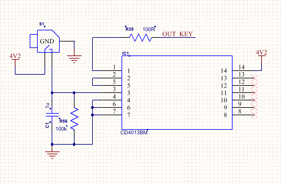
Fig. 10. Wiring diagram CD4013BM.
Pin "OUT_KEY" goes on foot switching on (EN) DC / DC AP3418 (it makes 3V3). Thus, consumption is minimal.
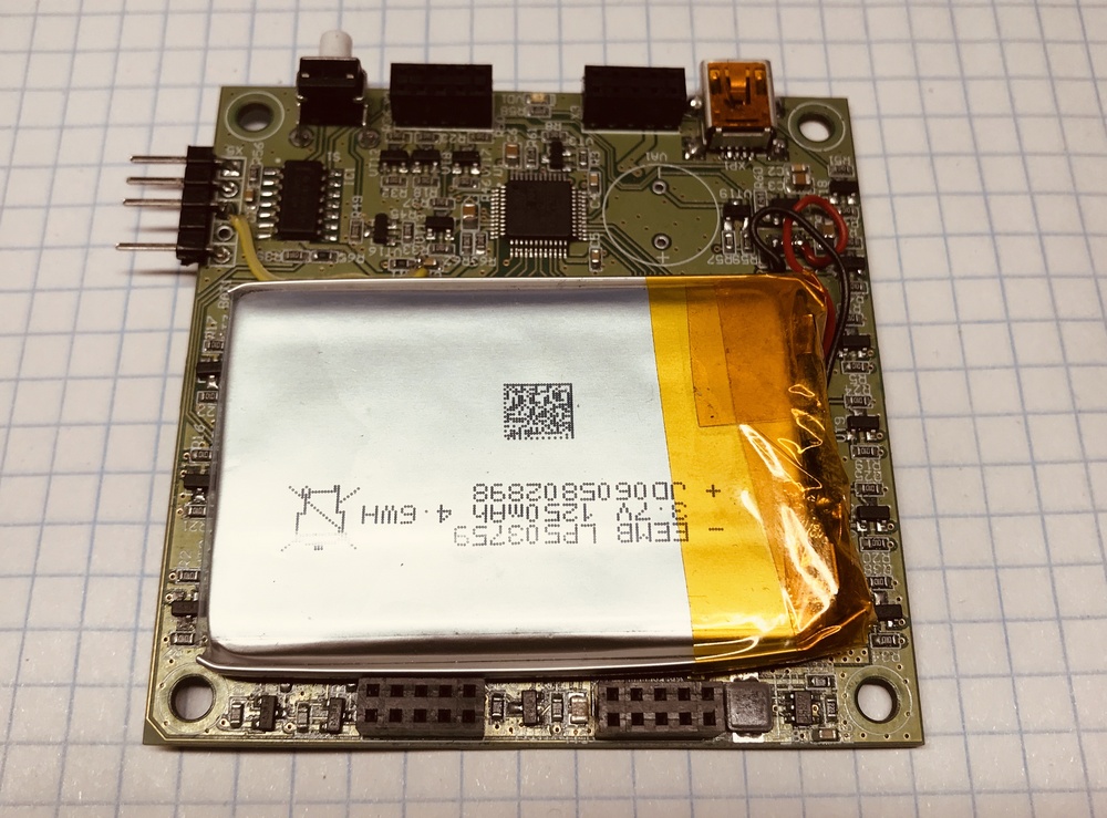
Fig. 11. Board with a microcontroller and battery.
7. The hull is still at the design stage. It is planned to just a neat box with frosted 1.5mm plexiglass on top.
When I put some sheets of paper on top to see how the translucency was going on, I realized that it was a fiasco. No, it shows through perfectly, but the field lines are not visible. Therefore, in “Fig. 2. "4 additional LEDs installed in the corners of the central square are visible (they are not on my welded board). If everything works out how it looks in my head, then if I do the milling on the reverse side of the Plexiglas, then these 4 blue LEDs will give 4 thin beams, which form the field markup, which will turn on when the device is turned on. If the rays do not work, then in any case milling will be visible.
There is a speaker on the board, but with a built-in generator it does not fit in height, and I don’t have one without a generator. I think that the vibration motor from the phone will come to this place and there will be a vibration response when pressed and won.
As a result, I can say that the toy was very interesting. The photo does not convey the whole effect, but the crosses and zeros look great, without any glare. It's a pleasure to play! The buttons work perfectly and the size of the field is very convenient. When the body is ready, I will definitely post a photo.
See you again!
UPD:
Added prices when purchasing components for 1 device, maybe I forgot something. Fees and assembly did not count. Something can be changed to cheaper.
1. STM32F100C4T6B - 1pc - 130r.
2. CD4013BM - 1pc - 16p.
3. LTC4054 - 1pc - 5p.
4. AP3418KTR - 1pc - 30r.
5. IRLML6401TRPBF (Si2307DS) - 18 pcs - 11 p.
6. LP503759 -
1 pc - 300r. 7. C191KRCT / C191KGCT - 148 pcs. - 436 p.
8. TTP223 - 8pcs - 40r.
9. Button, connector, passive - a bunch - 100r.
10. Fees
11. Assembly
Total: 1068r.
UPD:
Video Link
As you may have guessed from the photograph, today we are not talking about the classification of brandy. I will do the game of tic-tac-toe ... Who cares - I ask under the cat ->
The idea, as always, was born spontaneously. Once, on a quiet autumn evening, I drew nine squares on a leaf and suggested that my daughter play a new game for her. Having played several times, I saw that there was genuine interest ... and then Ostap suffered.
It would seem that it is easier to continue to draw the cells on a piece of paper or download the program to the phone, but is it interesting? Not!
What I wanted to get:
- Compact device on a battery (all sorts of capacitive cars and MIPI displays disappear immediately).
- Accordingly, charging from USB (preferably with an indication).
- Minimum time spent on fees and software (well, as usual, in general).
- Touch buttons.
- Intellectual device with the ability to play with the controller (without a second player). Switch to one and two players.
- Turn on / off with one button and preferably non-touch, so as to prevent accidental switching on.
- Housing printed on a 3D printer + frosted glass to close the LEDs.
First things first.
1. So, it was decided to take the controller STM32F100. On it, I can fully implement the simple logic of the game to begin with. On the case with 48 legs, all GPIOs are occupied (without the use of multiplexers and expanders). For each cross and zero, 8 LEDs (connected in parallel) are used, which are switched by field workers (IRLML6401).
The device consists of two boards, one with LEDs and touch buttons, the second with a controller, charging, battery, etc. Connected with connectors with a pitch of 2mm, between the boards is a 1250mA battery.
Fig. 1. The controller board
Fig. 2. Fee LEDs
A few days later the fees finally came out of production. I had the feeling that the game would be uncomfortable because of the size or the touch buttons. Looking ahead to say that playing is very cool! Buttons work fine through plexiglass 1.5-2mm.
Fig. 3. TOP side of the controller board and LEDs
. 4. BOTTOM side of the controller board and LEDs
2. Charging scheme is the simplest one I poke into such devices.
Fig. 5. Charge controller circuit.
3. Everything would be fine, but there were more components than I expected, and I was tormented by soldering. That's what happened after the soldering.
Fig. 6. The controller board with the components of
Fig. 7. LED board with components
Fig. 8. LED board with components on the side of the touch buttons.
The first, and so far the only, version of the software I did on if and in one infinite loop. Simple and works without bugs. When winning, the entire field goes out and the winning combination blinks twice.
4. I decided to implement the touch buttons on the TTP223 chips, I already used them in one of my projects. They are not demanding for wiring and for the presence / absence of a polygon under the sensor.
Fig. 9. The scheme of inclusion of the touch buttons.
I had more than 9pcs of them, so I decided not to use the multiplexer and hang each button on my GPIO controller.
5. Next I plan to integrate the game algorithm with the controller (I have already found several decent options). Switching for now is planned to be made by clamping the central touch button before switching on (but this is not yet final).
6. I thought for a long time how to implement on / off with one button in a simple way. The fastest and correct option, in my opinion, is on transistors and using two GPIO controllers, which I don’t have. Therefore, put the chip CD4013BM. Switching on is performed by pressing for about 1s, switching off by quick pressing. Works great.
Fig. 10. Wiring diagram CD4013BM.
Pin "OUT_KEY" goes on foot switching on (EN) DC / DC AP3418 (it makes 3V3). Thus, consumption is minimal.
Fig. 11. Board with a microcontroller and battery.
7. The hull is still at the design stage. It is planned to just a neat box with frosted 1.5mm plexiglass on top.
When I put some sheets of paper on top to see how the translucency was going on, I realized that it was a fiasco. No, it shows through perfectly, but the field lines are not visible. Therefore, in “Fig. 2. "4 additional LEDs installed in the corners of the central square are visible (they are not on my welded board). If everything works out how it looks in my head, then if I do the milling on the reverse side of the Plexiglas, then these 4 blue LEDs will give 4 thin beams, which form the field markup, which will turn on when the device is turned on. If the rays do not work, then in any case milling will be visible.
There is a speaker on the board, but with a built-in generator it does not fit in height, and I don’t have one without a generator. I think that the vibration motor from the phone will come to this place and there will be a vibration response when pressed and won.
As a result, I can say that the toy was very interesting. The photo does not convey the whole effect, but the crosses and zeros look great, without any glare. It's a pleasure to play! The buttons work perfectly and the size of the field is very convenient. When the body is ready, I will definitely post a photo.
See you again!
UPD:
Added prices when purchasing components for 1 device, maybe I forgot something. Fees and assembly did not count. Something can be changed to cheaper.
1. STM32F100C4T6B - 1pc - 130r.
2. CD4013BM - 1pc - 16p.
3. LTC4054 - 1pc - 5p.
4. AP3418KTR - 1pc - 30r.
5. IRLML6401TRPBF (Si2307DS) - 18 pcs - 11 p.
6. LP503759 -
1 pc - 300r. 7. C191KRCT / C191KGCT - 148 pcs. - 436 p.
8. TTP223 - 8pcs - 40r.
9. Button, connector, passive - a bunch - 100r.
10. Fees
11. Assembly
Total: 1068r.
UPD:
Video Link