Designing a service robot. Problem statement, solution architecture
We with a team ( which you can join ) like-minded people from Habr are developing a robot for collecting golf balls at the driving range .
Vladimir Goncharov Shadow_ru talks about collecting requirements, formulating tasks for work, developing architecture and creating a prototype for running software.
The project for me began with the collection of requirements, synthesis and subsequent decomposition into subtasks. The task for the robot at first glance is simple, but errors at the planning stage spoil the result of the work and are not always immediately visible, so skipping this stage is the path to nowhere.
Summarizing requirements simplifies communication with other team members - a common understanding of the task is developed, the situation when a robot in your head no longer arises. Also, when a new member enters the team - it is enough to give a similar document to read, which reduces the time for the entry phase.
There is always a balance between the collection of requirements and generalizations - I want to paint in more detail, but if you are not a lawyer, used to working with hundreds of related paragraphs, the task of a common vision will not solve it. There is of course the right approach when there are several cuts of requirements for different team members and external customers-contractors. But while it is clearly unnecessary, because Each change in requirements will lead to a serious investment of time for updating such slices, which does not affect the productivity of a startup too well.
For myself, I decided to break into functional and non-functional requirements and put it all into one A4 page. The first version came out like this:
Objective: It requires the most uninterrupted detour of a training golf course in difficult climatic conditions for collecting balls.
Problem: Unmanned Ground Vehicle ( UGV ) is required to perform cyclical missions to bypass the space defined by the perimeter with the coordinates of points in WGS-84 notation.
Missions should include the following operations:
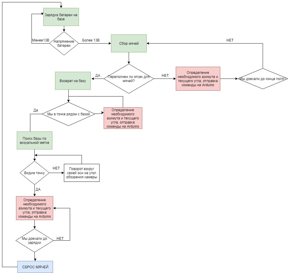
Simplified version of the algorithm
In addition, the UGV must fulfill the following requirements:
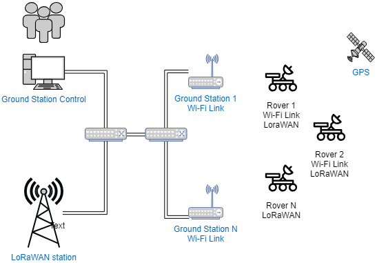
According to these requirements, the following solution architecture was chosen:
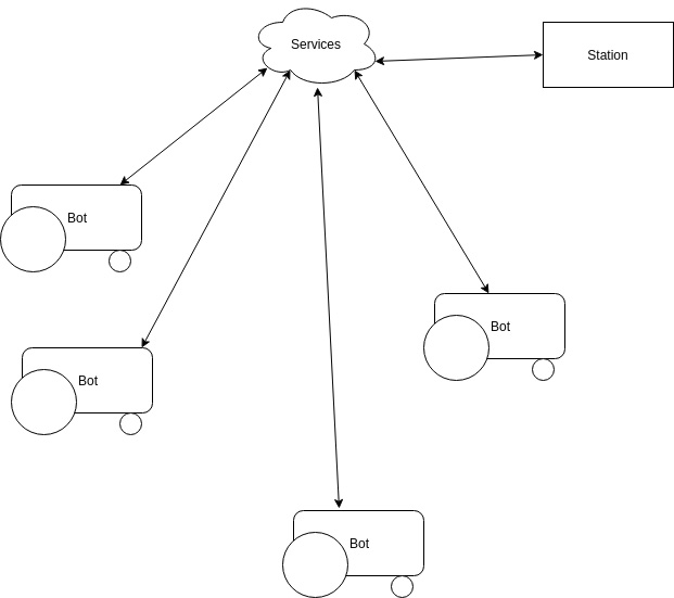
The structure of the robotic complex includes: one control center (Ground Station Control) - then GSC .
Allows the user to perform the following actions:
GSC software should be engaged in planning the actions of golf robots, the robots themselves should be fairly simple. The solution is not very flexible, of course, but self-consistent solutions and mesh networks are not something that can be solved in a short time, and even cheap. Plus - this is a typical approach, and therefore known problems. One or more golf robots (Golf rover) - hereinafter GR .
Performs the following typical actions:
Since ground stations can be 1, and GR is a lot - filling the bunker of balls related to an emergency. This solves two problems at once - GSC with a high degree of confidence knows that the robot went to the station and frequently tested the backup channel. It is also assumed that the balls should be filled during the mission and if this is not the case - GSC was mistaken in planning somewhere and it is worth fixing it. Intuitively, I want to release the robot in the open field, and when it collects the balls, it will return. But then the economy comes into play, if one or two people are involved - it is better for the robot to stand at the station, and start moving when the balls have already accumulated. Less resource and energy consumption.
One or more ground stations (Ground Station) - further GS.
The scheme of the whole complex is as follows:
For good it is necessary to give a table of risks and their ratings, but I'm afraid three A4 sheets will cause only a yawn. I will give only an interesting squeeze:
The main problem of all autonomous crawling rovers is the task of obtaining their exact position. Moreover, the position must be really accurate - preferably within 10-15 cm. Precisely because this task cannot be solved properly on a small mobile platform, there are no cheap and massive agricultural / transport / military drones.
Although it would seem - that there are solutions for flying drones, reuse on the ground and that's it. But it’s in the air 10–15 meters to the left or to the right at the turn does not solve almost anything, but on the ground it will lead to accidents and catastrophes. In addition, the stones do not change their place in the air, the living creatures do not cross the road. The birds are still yes, but the places in the air are much bigger.
Positioning is carried out on the GPS / GLONASS module, which immediately leads to two consequences: the positioning accuracy is not too high and the speed of obtaining coordinates. Coordinates for the uBlox M8N module for stationary tests: 2-3 meters in good reception conditions, 7-10 in bad weather conditions and visibility. In general, such errors for the task of collecting balls are even good - for several missions the rover will capture balls more than driving along the tracks. However, in this case, it turns out that it is impossible to drive it near obstacles such as walls or large stones, and in these areas the balls will accumulate. Optical and ultrasound navigation systems were analyzed, but it turned out that a large number of beacons / cameras is needed for complex field geometry, there are problems with visibility zones (the field is not always even as the floor in the hangar) and the unstable operation of such systems under difficult weather conditions (rain, fog). So while our GPS is all, but with reservations. Moreover, it is possible to improve the accuracy of GPS quite cheaply - RTK, but it will not solve the problem of walls.
It became clear that the chosen approach, when the rover crawls over the loaded points with an accuracy of 5-10 meters left-right, requires verification. Getting on the train called SLAM with feet for a simple task seems superfluous. If entering the station by optically bright objects (Aruco Code), how to make it clear, and how much resources it requires is the same, then solving the classifier problem for all possible objects on the field or finding the boundaries is a completely different task.
It is necessary to make a mock-up of the system, test it in action on the field, and evaluate its applicability. According to the elaborated requirements, the business went much more fun:
As Ardurover was chosen as a software for the rover, it is an actively developing software, starting as firmware for quadcopters on Arduino. However, by now it also supports Linux-based cards with RTL core, and is open for revisions. In the future, I had to finish the word by word, but rather to speed up the work than out of need. BeagleBone Blue , a highly integrated system for robotics,
was chosen as the rover’s brains .
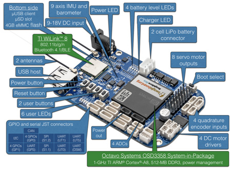
A distinctive feature is the use of TI Sitara / Octavo chips, compared to those of the same Raspberry there are Programmable Realtime Unit - PRU. These are two separate 200 MHz cores that can control real-time hardware without interrupting the main core with interrupts, threads, and other techno-magic.
In addition, the platform immediately has WiFi, Bluetooth, a soldered connector for a balancing cable, a Li-Po battery charging controller, USB connectors for connecting telemetry and a computer, connectors for servo motors, power stabilizers 5 and 3.3 volts, ADC immediately wound up to one channel per battery, several UART. In general, take it and make a robot.
Ardurover got there not without problems - using the PRU from the software at the current time is only possible with the 4.4 LTS core. In newer kernels, programming the PRU from user software results in a SIGBUS fault, after talking with the developers of the ardublue branch I ordered the JTAG adapter, I will look at the reason. The rover doesn’t interfere with living at all, but I want a clear understanding of what the problem is.
The software allows you to do almost all of the requirements, except for positioning to check into the database, here I use the camera JeVois-A33. He will not send an alarm signal on the part of events either, but this is a task for a separate module with separate power supply, since power failure or a good coup control module can not survive.
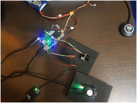
It remains to buy a GPS receiver, a telemetric radio transmitter, an ultrasonic distance sensor and connect a machine vision camera. After soldering, connecting connectors and test run it turned out like this:
Mission Planner is used as a control center .
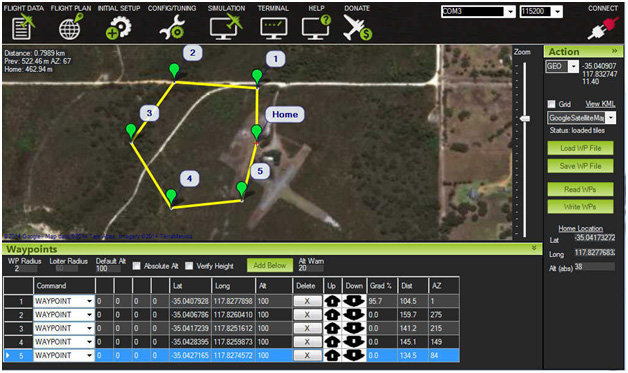
The software is not indisputable, a decent Web interface instead of a Swiss knife with 100,500+ buttons for lovers of copters needs to be done, but for debugging purposes it is more than suitable. Much is written to communicate with the rover using the MAVLINK protocol of adapters and application software for Java / JS. In the protocol, I would certainly like to have smaller packages and maintain a standard reference guide of parameters, but that would be too good.
As a rover base, a 1/18 scale model machine with separate receiver and engine controller is used.
The receiver was ejected, the servo and motor controller connectors were wired directly to the BeagleBone Blue, as was the battery.
From the ridiculous - I remembered that as a child I couldn’t solder at all, on the places of soldering all the time the snot of the tin hung and I took the soldering iron not without inner thrill. However, as soon as the knife, the wire and the soldering iron fell into my hands, I did a good trick to the sting, cut off the insulation without hitting the internal core, hands themselves twisted the ends of the cable, sealed them and sealed the connection. And then I remembered that I started working as an embedded developer and in a couple of months I got into contact with a soldering iron. A beautiful illustration of the saying “experience is not lost”, in my opinion.
At the moment the stand looks like this:
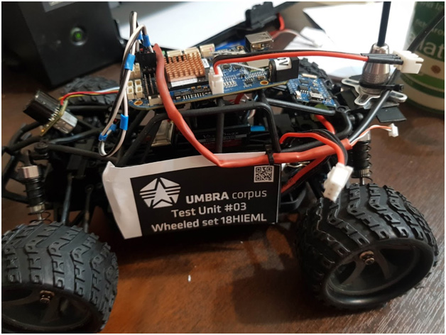
As you can see - the controller without housing and fasteners. Unfortunately, I ordered the pseudohermobox to print on an SLS 3D printer with nylon, and have not had time to do it yet. To deduce the rover in a pure field without a hull - a move to such a viking for half an hour in the open air. Then either electrochemical corrosion will finish the doze, or after a coup-strike, it is completely out of the discharge. So we are waiting for the hull, hermetic connectors and fasteners according to all the rules of shock and vibration damping.
On the video detection rover Aruco Code
As a result, the test pokatushki I spent at home on the manual control. It turned out that the base was chosen not quite right - it accelerates too quickly, I had to learn the programming of the Chinese motor controller. The second - the reverse of this miracle of Chinese thought is activated by two “back” signals - the first turns on braking, the second one already turns on the reverse. And it can be ignored when the signal is too fast - it protects the life of gears and the engine. I had to finish the ardurover, because similar tricks were not included in it.
The following actions are to roll back the route 5-7 times, remove the telemetry logs and GPS tracks of the routes. I found a football stadium with a heated field, so if it snows, it's not scary. Rover obviously will not be drilling snowdrifts, otherwise Faina Ranevskaya would be worth adding to the list of perversions, apart from field hockey and ballet on ice, also golf through snowdrifts. Not the cheapest entertainment, of course, but where else in Russia, and in November you can find green grass. Also, work began on the implementation of tracked chassis, there is much lower speed (the current model accelerates to 20 km / h in 15 seconds) and there is a U-turn on the spot, and not trips on the patch. Most likely in a couple of weeks, both chassis will be run in at the same time to test the operation of the obstacle detector and detour algorithms.
In the end, I want to note that testing solutions on full-scale models is quite fast and cheap. Small troubles are caught much earlier, and moreover - there is time to make changes to the design of a large robot, while it is still at the design or prototype stage. Then it will be more expensive, longer, and something will break in linking the nodes. And on such models, almost all the necessary software for tasks is easily developed and checked. Ideally, all you need to switch to another model is to replace the protocol of the motor controller with a new one. Well, it is possible to change the dynamic model.
In addition, the use of specialized and tested solutions greatly save time and effort. It is certainly fascinating to invent your high-density installation board, your communication protocol, ground-based software and rover software, to debug obstacle avoidance algorithms and communications with Chinese engine controllers, but in this case you can immediately add six months or a year to the long and thorny path. Already passed by someone.
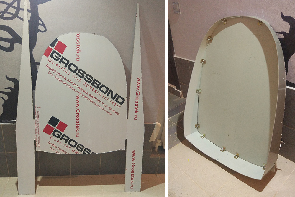
We are preparing the second version of the case. During the week, the case will be ready by the method of vacuum forming, we will write about this in a separate post.
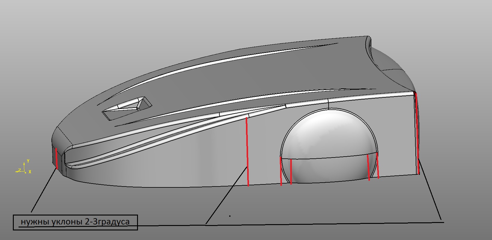
We manufacture the lower part of the body by milling a composite material.
The hull and mechanics are designed by NikitaKhvoryk . We are waiting for n12eq3 for a very long time to connect the modules for the raspberry pi and orange pi versions . Version with Ardupilot Vladimir Goncharov Shadow_ru
Thank you for the help and advice offered Process0169 , Trif , tersuren , vasimv , vovaekb90, Vyacheslav Soldatov, Levon Zakaryan, Sergey Pomazkin, Vladi Kuban, Karen Musaelyan, Alexey Platonov. If you want to help - please write to me in the LAN or VC , FB .
We have preliminary arrangements for placing a test robot at golf clubs in Russia, Germany, Latin America and New Zealand. In the near future plans to refine the algorithms and design, conduct tests in Moscow and make improvements. Create 5 robots and place them for free at golf clubs for long tests for the new season.
Thank you for reading, ask and criticize us completely.
Vladimir Goncharov Shadow_ru talks about collecting requirements, formulating tasks for work, developing architecture and creating a prototype for running software.
The project for me began with the collection of requirements, synthesis and subsequent decomposition into subtasks. The task for the robot at first glance is simple, but errors at the planning stage spoil the result of the work and are not always immediately visible, so skipping this stage is the path to nowhere.
Summarizing requirements simplifies communication with other team members - a common understanding of the task is developed, the situation when a robot in your head no longer arises. Also, when a new member enters the team - it is enough to give a similar document to read, which reduces the time for the entry phase.
There is always a balance between the collection of requirements and generalizations - I want to paint in more detail, but if you are not a lawyer, used to working with hundreds of related paragraphs, the task of a common vision will not solve it. There is of course the right approach when there are several cuts of requirements for different team members and external customers-contractors. But while it is clearly unnecessary, because Each change in requirements will lead to a serious investment of time for updating such slices, which does not affect the productivity of a startup too well.
For myself, I decided to break into functional and non-functional requirements and put it all into one A4 page. The first version came out like this:
Phase 1. Problem statement
Objective: It requires the most uninterrupted detour of a training golf course in difficult climatic conditions for collecting balls.
Problem: Unmanned Ground Vehicle ( UGV ) is required to perform cyclical missions to bypass the space defined by the perimeter with the coordinates of points in WGS-84 notation.
Missions should include the following operations:
- Normal start from a known home position
- Emergency start from an unknown position beforehand (start after WD triggered, power protection, etc.)
- Detour of the area with coverage of at least 98% of the space in 1 or several races (it is unnecessary to start the detour again after filling the bunker in 15 minutes)
- Return to the home position on filling the bunker, depleting the battery, the end of a detour
- Arrival at the launch platform to reset the balls, charge the batteries
Simplified version of the algorithm
In addition, the UGV must fulfill the following requirements:
- Do not leave the specified perimeter during a detour of a given perimeter
- The home position may be outside the specified perimeter.
- Monitor battery consumption and plan returns based on consumed power. Moving a full bin requires more power from the battery than an empty one.
- Log telemetry logs including, but not limited to coordinates on the plane, values of 6 axes of rotation, the level of the telemetry signal and external sensors.
- Have three positioning systems - GPS for obtaining coarse coordinates, IMU for verifying and correcting coordinates on a plane, optical for precise positioning by markers.
- Have two Watch Dog systems - software and hardware. Software verifies the state
- Have a long-range emergency communication channel with a separate power supply, which is used when the parameters of the mission go beyond the specified parameters (coordinates, accident, power failure, equipment failure)
- Have the ability to change the parameters of the mission while on the home position
- Have two communication channels - low-speed telemetry and high-speed for transmission of audiovisual information. High-speed should have the ability to enable / disable telemetry team.
According to these requirements, the following solution architecture was chosen:
The structure of the robotic complex includes: one control center (Ground Station Control) - then GSC .
Allows the user to perform the following actions:
- Set perimeter
- Plan missions depending on time of day and court load
- Have the ability to monitor golf robots with a reading of at least 1 minute
- Have the ability to interrupt missions
GSC software should be engaged in planning the actions of golf robots, the robots themselves should be fairly simple. The solution is not very flexible, of course, but self-consistent solutions and mesh networks are not something that can be solved in a short time, and even cheap. Plus - this is a typical approach, and therefore known problems. One or more golf robots (Golf rover) - hereinafter GR .
Performs the following typical actions:
- Receives a mission when in a radius of 10 meters from the ground station
- Performs a mission
- In a typical mission, it reports via a telemetric channel with a frequency of at least 1 time per minute.
- Returns to the ground station
- Waiting for a new mission
- Each mission must be interrupted by the following events:
- Ball hopper filling
- Power failure
- Impossibility of movement (coup, sudden obstacle)
- Emergency restart
- Manual mission interruption
- Each interruption of the mission must be transmitted via conventional telemetry and backup channel
- After interruption - GR returns to the ground station if its condition allows
Since ground stations can be 1, and GR is a lot - filling the bunker of balls related to an emergency. This solves two problems at once - GSC with a high degree of confidence knows that the robot went to the station and frequently tested the backup channel. It is also assumed that the balls should be filled during the mission and if this is not the case - GSC was mistaken in planning somewhere and it is worth fixing it. Intuitively, I want to release the robot in the open field, and when it collects the balls, it will return. But then the economy comes into play, if one or two people are involved - it is better for the robot to stand at the station, and start moving when the balls have already accumulated. Less resource and energy consumption.
One or more ground stations (Ground Station) - further GS.
- Charging
- Ball Bunker
- Contact GR
The scheme of the whole complex is as follows:
The second phase is the assessment of risks and possible problems of the whole complex.
For good it is necessary to give a table of risks and their ratings, but I'm afraid three A4 sheets will cause only a yawn. I will give only an interesting squeeze:
The main problem of all autonomous crawling rovers is the task of obtaining their exact position. Moreover, the position must be really accurate - preferably within 10-15 cm. Precisely because this task cannot be solved properly on a small mobile platform, there are no cheap and massive agricultural / transport / military drones.
Although it would seem - that there are solutions for flying drones, reuse on the ground and that's it. But it’s in the air 10–15 meters to the left or to the right at the turn does not solve almost anything, but on the ground it will lead to accidents and catastrophes. In addition, the stones do not change their place in the air, the living creatures do not cross the road. The birds are still yes, but the places in the air are much bigger.
Positioning is carried out on the GPS / GLONASS module, which immediately leads to two consequences: the positioning accuracy is not too high and the speed of obtaining coordinates. Coordinates for the uBlox M8N module for stationary tests: 2-3 meters in good reception conditions, 7-10 in bad weather conditions and visibility. In general, such errors for the task of collecting balls are even good - for several missions the rover will capture balls more than driving along the tracks. However, in this case, it turns out that it is impossible to drive it near obstacles such as walls or large stones, and in these areas the balls will accumulate. Optical and ultrasound navigation systems were analyzed, but it turned out that a large number of beacons / cameras is needed for complex field geometry, there are problems with visibility zones (the field is not always even as the floor in the hangar) and the unstable operation of such systems under difficult weather conditions (rain, fog). So while our GPS is all, but with reservations. Moreover, it is possible to improve the accuracy of GPS quite cheaply - RTK, but it will not solve the problem of walls.
It became clear that the chosen approach, when the rover crawls over the loaded points with an accuracy of 5-10 meters left-right, requires verification. Getting on the train called SLAM with feet for a simple task seems superfluous. If entering the station by optically bright objects (Aruco Code), how to make it clear, and how much resources it requires is the same, then solving the classifier problem for all possible objects on the field or finding the boundaries is a completely different task.
It's time for Phase 3 - Proof of Concept
It is necessary to make a mock-up of the system, test it in action on the field, and evaluate its applicability. According to the elaborated requirements, the business went much more fun:
As Ardurover was chosen as a software for the rover, it is an actively developing software, starting as firmware for quadcopters on Arduino. However, by now it also supports Linux-based cards with RTL core, and is open for revisions. In the future, I had to finish the word by word, but rather to speed up the work than out of need. BeagleBone Blue , a highly integrated system for robotics,
was chosen as the rover’s brains .
A distinctive feature is the use of TI Sitara / Octavo chips, compared to those of the same Raspberry there are Programmable Realtime Unit - PRU. These are two separate 200 MHz cores that can control real-time hardware without interrupting the main core with interrupts, threads, and other techno-magic.
In addition, the platform immediately has WiFi, Bluetooth, a soldered connector for a balancing cable, a Li-Po battery charging controller, USB connectors for connecting telemetry and a computer, connectors for servo motors, power stabilizers 5 and 3.3 volts, ADC immediately wound up to one channel per battery, several UART. In general, take it and make a robot.
Ardurover got there not without problems - using the PRU from the software at the current time is only possible with the 4.4 LTS core. In newer kernels, programming the PRU from user software results in a SIGBUS fault, after talking with the developers of the ardublue branch I ordered the JTAG adapter, I will look at the reason. The rover doesn’t interfere with living at all, but I want a clear understanding of what the problem is.
The software allows you to do almost all of the requirements, except for positioning to check into the database, here I use the camera JeVois-A33. He will not send an alarm signal on the part of events either, but this is a task for a separate module with separate power supply, since power failure or a good coup control module can not survive.
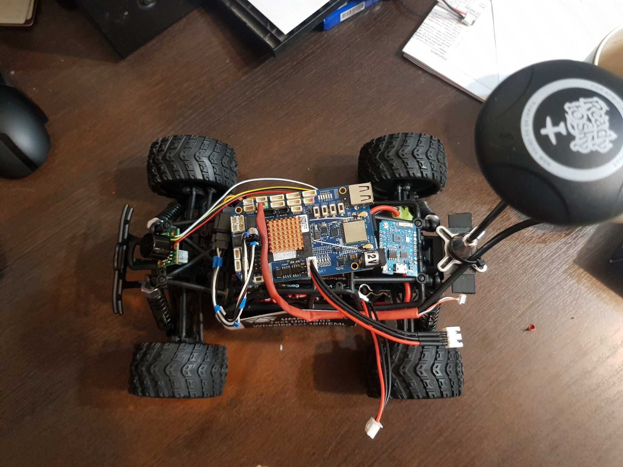
It remains to buy a GPS receiver, a telemetric radio transmitter, an ultrasonic distance sensor and connect a machine vision camera. After soldering, connecting connectors and test run it turned out like this:
Mission Planner is used as a control center .
The software is not indisputable, a decent Web interface instead of a Swiss knife with 100,500+ buttons for lovers of copters needs to be done, but for debugging purposes it is more than suitable. Much is written to communicate with the rover using the MAVLINK protocol of adapters and application software for Java / JS. In the protocol, I would certainly like to have smaller packages and maintain a standard reference guide of parameters, but that would be too good.
As a rover base, a 1/18 scale model machine with separate receiver and engine controller is used.
The receiver was ejected, the servo and motor controller connectors were wired directly to the BeagleBone Blue, as was the battery.
From the ridiculous - I remembered that as a child I couldn’t solder at all, on the places of soldering all the time the snot of the tin hung and I took the soldering iron not without inner thrill. However, as soon as the knife, the wire and the soldering iron fell into my hands, I did a good trick to the sting, cut off the insulation without hitting the internal core, hands themselves twisted the ends of the cable, sealed them and sealed the connection. And then I remembered that I started working as an embedded developer and in a couple of months I got into contact with a soldering iron. A beautiful illustration of the saying “experience is not lost”, in my opinion.
At the moment the stand looks like this:
As you can see - the controller without housing and fasteners. Unfortunately, I ordered the pseudohermobox to print on an SLS 3D printer with nylon, and have not had time to do it yet. To deduce the rover in a pure field without a hull - a move to such a viking for half an hour in the open air. Then either electrochemical corrosion will finish the doze, or after a coup-strike, it is completely out of the discharge. So we are waiting for the hull, hermetic connectors and fasteners according to all the rules of shock and vibration damping.
On the video detection rover Aruco Code
As a result, the test pokatushki I spent at home on the manual control. It turned out that the base was chosen not quite right - it accelerates too quickly, I had to learn the programming of the Chinese motor controller. The second - the reverse of this miracle of Chinese thought is activated by two “back” signals - the first turns on braking, the second one already turns on the reverse. And it can be ignored when the signal is too fast - it protects the life of gears and the engine. I had to finish the ardurover, because similar tricks were not included in it.
The following actions are to roll back the route 5-7 times, remove the telemetry logs and GPS tracks of the routes. I found a football stadium with a heated field, so if it snows, it's not scary. Rover obviously will not be drilling snowdrifts, otherwise Faina Ranevskaya would be worth adding to the list of perversions, apart from field hockey and ballet on ice, also golf through snowdrifts. Not the cheapest entertainment, of course, but where else in Russia, and in November you can find green grass. Also, work began on the implementation of tracked chassis, there is much lower speed (the current model accelerates to 20 km / h in 15 seconds) and there is a U-turn on the spot, and not trips on the patch. Most likely in a couple of weeks, both chassis will be run in at the same time to test the operation of the obstacle detector and detour algorithms.
In the end, I want to note that testing solutions on full-scale models is quite fast and cheap. Small troubles are caught much earlier, and moreover - there is time to make changes to the design of a large robot, while it is still at the design or prototype stage. Then it will be more expensive, longer, and something will break in linking the nodes. And on such models, almost all the necessary software for tasks is easily developed and checked. Ideally, all you need to switch to another model is to replace the protocol of the motor controller with a new one. Well, it is possible to change the dynamic model.
In addition, the use of specialized and tested solutions greatly save time and effort. It is certainly fascinating to invent your high-density installation board, your communication protocol, ground-based software and rover software, to debug obstacle avoidance algorithms and communications with Chinese engine controllers, but in this case you can immediately add six months or a year to the long and thorny path. Already passed by someone.
Need your help:
- If you are ready to work on the ROS version.
- Requires preparation of the module connection board for the raspberry pi and orange pi version
- Assistance with driving range testing, especially if you live in a country where you actively play golf;
- Legal issues, the removal of the robot from the country, patent law, legislative requirements for the design;
- Need help with packing a startup, looking for investment. We are developing well and without investment, we have a plan of action, a team is being formed. What we need is not investor money, but experience and competence in developing a commercially successful project.
Current project status
We are preparing the second version of the case. During the week, the case will be ready by the method of vacuum forming, we will write about this in a separate post.
We manufacture the lower part of the body by milling a composite material.
The hull and mechanics are designed by NikitaKhvoryk . We are waiting for n12eq3 for a very long time to connect the modules for the raspberry pi and orange pi versions . Version with Ardupilot Vladimir Goncharov Shadow_ru
Thank you for the help and advice offered Process0169 , Trif , tersuren , vasimv , vovaekb90, Vyacheslav Soldatov, Levon Zakaryan, Sergey Pomazkin, Vladi Kuban, Karen Musaelyan, Alexey Platonov. If you want to help - please write to me in the LAN or VC , FB .
Plans:
We have preliminary arrangements for placing a test robot at golf clubs in Russia, Germany, Latin America and New Zealand. In the near future plans to refine the algorithms and design, conduct tests in Moscow and make improvements. Create 5 robots and place them for free at golf clubs for long tests for the new season.
Thank you for reading, ask and criticize us completely.