nanoCAD Mechanics 9.0: The Basics of Modern Design
nanoCAD Mechanics is a vertical solution for engineering design, based on the nanoCAD Plus platform from the Russian developer, Nanosoft. In addition to the rich functionality for the design and technological documentation for ESKD and ESTD, the program has all the basic tools of digital design.
The basic format of the program, DWG, the most popular in the world of engineering design, since the 90s of the last century remains the most common in the design companies of our country. Active participation of Nanosoft in the consortium Open Design Alliance ( www.opendesign.com) allows you to provide timely support for current versions of the format. Working with DWG is carried out directly - unlike many applications that work through the import / export of this format.
In conjunction with the modules of parameterization and 3D-modeling, nanoCAD Mechanics allows you to create three-dimensional intelligent objects that provide the ability in several actions, based on the prototype, to create a variety of designs not only of individual parts, but also of nodes consisting of a large number of components. And then create associative drawings for the created models and manage their geometry through the parameters incorporated in the construction of 3D-models.
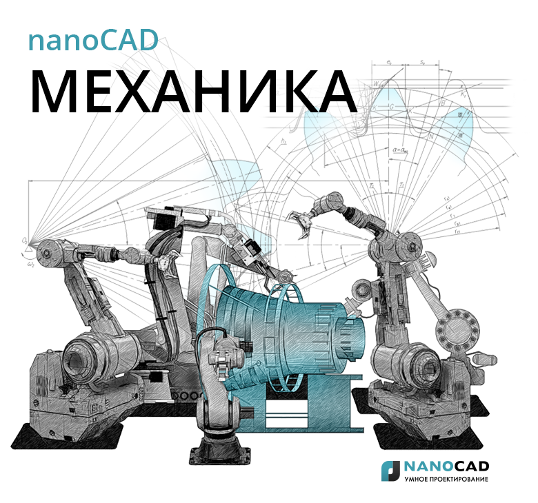
The standard delivery of nanoCAD Mechanics, along with other tools, includes a base of drawings and 3D models of standard products, structural and technological elements (fasteners, bearings, elements of pipeline fittings, grooves, holes, as well as the main and auxiliary tools, equipment for the design of technological sketches and much other). The elements of the base are made in accordance with GOST and the most well-known international standards, such as ISO, DIN, CSN (Fig. 1). At the same time, many elements are parametric and, in addition to internal dependencies, have external connections with the corresponding elements, operating within the framework of selected standards.
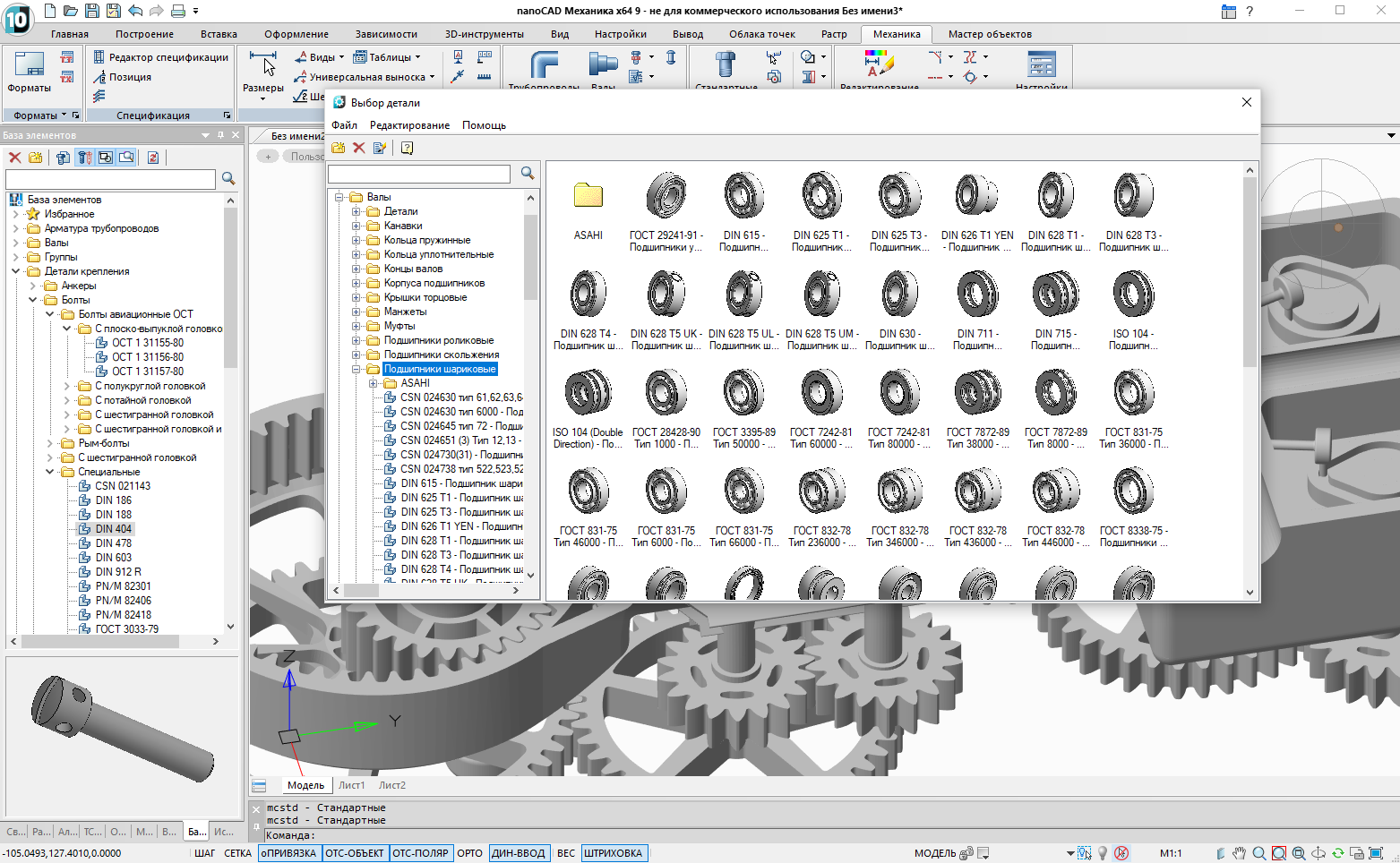
Fig. 1. Catalog of standard elements nanoCAD Mechanics
The base is open to replenish user items. The toolkit of the program allows you to create them parametric and impose connections with other elements. Details of the creation of parametric elements and database filling are presented in the article “Creating parametric database objects in nanoCAD Mechanics” ( https://habr.com/company/nanosoft/blog/346704 ). Thus, with proper use of the program's functionality, it is possible to create parametric multi-component assemblies.
To work with rotation bodies, so often used in mechanical engineering, nanoCAD Mechanics offers a specialized module (Fig. 2), which accelerates the design process thanks to a user-friendly interface and the presence of the most popular structural elements, typical shaft sections: shaft ends, threaded and splined surfaces, and veneer grooves, spherical surfaces, etc. Using the shaft design module, you can develop both detailed and assembly drawings.
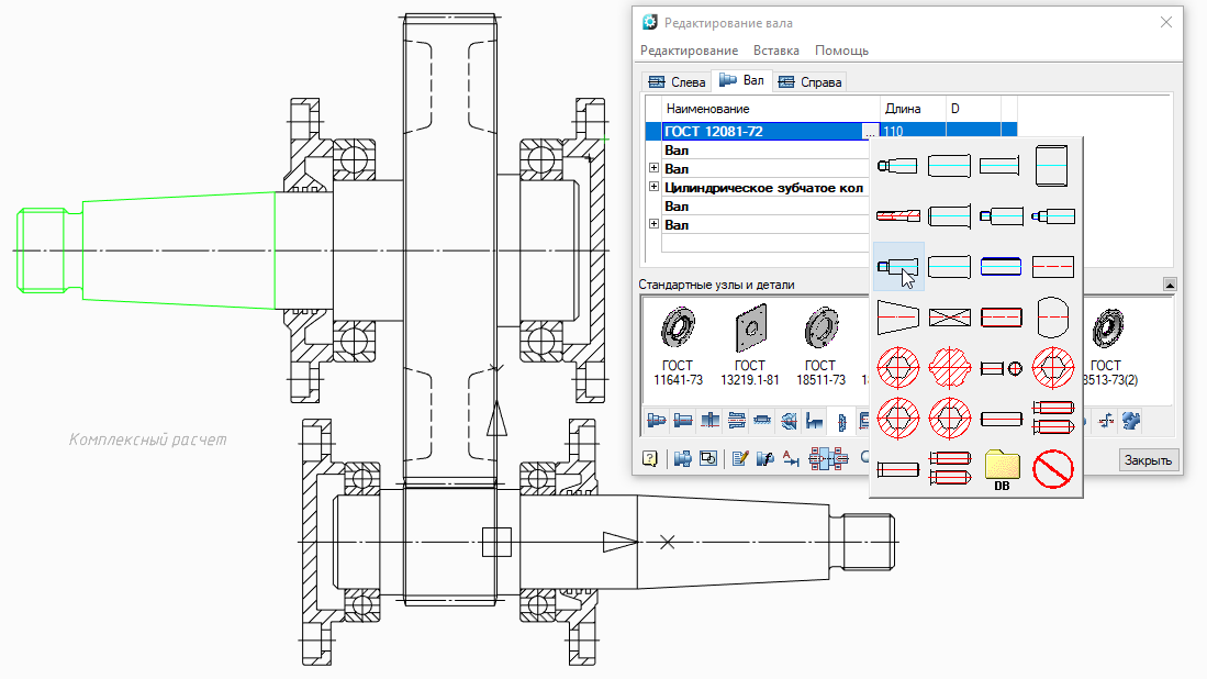
Fig. 2. Shaft Design Module
No engineering design is complete without calculations. That is why the developers of nanoCAD Mechanics have included in the toolkit of the program the appropriate design functionality that helps the design engineer to make the right decision at the initial stages of design. The functions implemented in the program include:
- strength calculation of the beam;
- static shaft calculation;
- calculation of bolted connections for strength;
- calculation of the service life of the bearings under given loading conditions;
- calculation of compression and extension springs,
as well as the calculation of gears of various types subject to the conditions of GOST 21354-87 and GOST 16532-70, taking into account hardness, safety factor, fatigue limits and a wide range of loads (Fig. 3). Calculations are possible even when the limits imposed by the Strength Standard are applied.
Fig. 3. Designing gears in nanoCAD Mechanics
The developers paid special attention to the program interface: it was worked out taking into account the numerous wishes of users and is intuitively clear (Fig. 4). Externally, nanoCAD Mechanics resembles a popular western solution, but upon closer inspection, significant differences are revealed, which appeared as a result of close cooperation between software developers and domestic users. The need for such interaction is obvious: whatever the number of representative offices or branches is opened by our Western or Eastern colleagues, it is very difficult for an ordinary user to reach their technical support services, not to mention the ability to somehow influence the decisions of developers of foreign software.
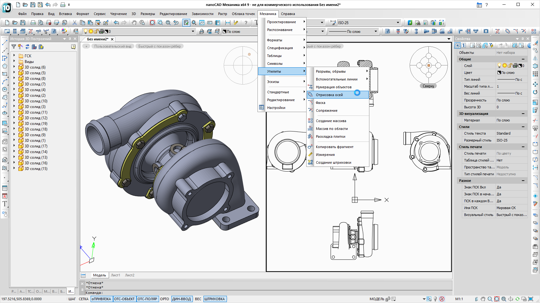
Fig. 4. Classic interface nanoCAD Mechanics
The nanoCAD Mechanics application has been developed since 2008, this is one of the first software solutions of Nanosoft. The ninth release of the product has recently been released (you can download its evaluation version at www.nanocad.ru/products/nanocadmech/download). Despite its young age (some CAD systems have existed for 30-40 years), nanoCAD Mechanics confidently occupied the market niche of an available workhorse capable of solving a fairly wide range of tasks, invariably remaining a convenient and understandable tool of a design engineer. I think I’m not mistaken in assuming that the products of the nanoCAD family conquer the market precisely thanks to a balanced balance of functionality (utility) and value. In addition, Nanosoft has a fairly loyal software licensing policy: there are temporary and permanent licenses, local and network. Users not previously familiar with the product are invited to install a fully functional version and activate an evaluation license, which will be valid for 30 days.
In the spring of this year, the nanoCAD Plus 10 platform came out (the capabilities of this release and its background are presented in Denis Ozhigin ’s fundamental article “The nanoCAD Plus 10 Russian CAD platform: a universal complex for those who design” ( https://habr.com/company/nanosoft / blog / 423253 ). The new release of nanoCAD Mechanics is built on the most stable version of the platform, thanks to which the users of nanoCAD Mechanics 9.0 will get the most streamlined solution.
Open beta testing
The stability of the new version is also significantly affected by the launch of external beta testing, which allowed to detect and eliminate a number of inaccuracies in the operation of the software.
In general, open beta testing is one of the most important stages in the development of software products, since only a real user who daily uses an application to solve specific problems can work out the most relevant test scenario. Of course, in the process of preparing the next version, internal testing is carried out, and not even one - there can be quite a few iterations, and the test scripts themselves are constantly changing, adapting to new realities. But the end user is always at the forefront, he is the most important task designer for software developers. Nanosoft appreciates the active beta testers of its software products, expressing its appreciation not only in words but also in the form of material incentives. For example, the most active beta testers nanoCAD Mechanic 9. 0 Beta is not only marked with mementoes, but also awarded with annual licenses. For his part, the author of these lines thanks everyone on behalf of the developers who participated in the beta testing. You can learn more about beta testing software products of the nanoCAD family at the company forum:forum.nanocad.ru . The latest news about the software of JSC Nanosoft, first-hand, is published on the site www.nanocad.ru/information ; our community VKontakte - vk.com/ncmechanica .
nanoCAD Mechanics 9.0: review of the new version
To begin with, we simply list the main innovations of the ninth version of the product:
- radically redesigned interface. At the same time, for users who do not like to change their habits in communication with the program, the opportunity to work in a well-known visual style is preserved;
- qualitatively new changes touched work with 3D-objects;
- responding to the wishes of users, the program developers continued the development of the Specification Editor;
- New features enriched design tools drawings.
And, of course, focusing on today's market needs, the developers of nanoCAD Mechanics 9.0 significantly replenished the base of standard products.
Let's look at new items more ...
Ribbon interface
The ribbon interface of the new release nanoCAD Mechanics is designed according to the wishes of users, is ergonomic and corresponds to the modern style, in which many popular applications are executed (Fig. 5).
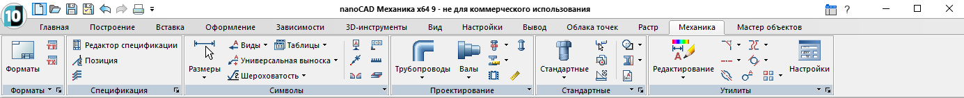
Fig. 5. Ribbon interface nanoCAD Mechanic 9.0
What are the advantages of a new style? Here are just some of them: the main teams are always in sight; The buttons of the most common commands are larger, which makes them stand out from the crowd. For the convenience of the user, all commands are grouped into sections in much the same way as in the menu of the classical scheme. Rarely used commands are hidden so as not to overload the interface, and are invoked by an additional click on the corresponding marker. By analogy with setting up toolbars in the classical scheme, the tape can also be customized depending on the wishes of the user.
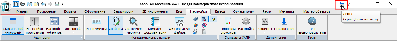
Fig. 6. Switching the visual style of the interface nanoCAD Mechanics 9.0
For those who, in their daily work, prefer the classical scheme of the interface, it is possible to quickly switch from one style to another. Just press the switch button, located in a prominent place (Fig. 6).
Improved navigation
For ease of navigation, when working with three-dimensional graphics, the Locator for changing views has appeared in the new version, and the management of visual styles for displaying models has been moved to the model space region. Now, switching to the desired view is possible with one click of the mouse, and changing the visual style of the object with two, while there is no need to reach far with the mouse pointer (Fig. 7).
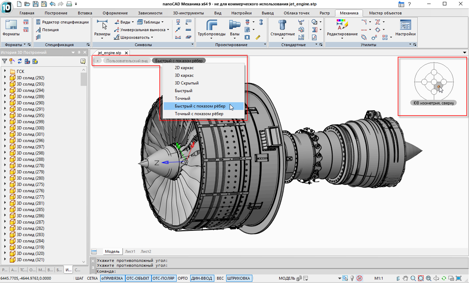
Fig. 7. New interface elements: quick access to visual styles, Locator
New Core 3D Modeling
With each new version, the nanoCAD 3D module is being improved. The ninth version was no exception: one more mathematical core was connected to the bulk modeling module.
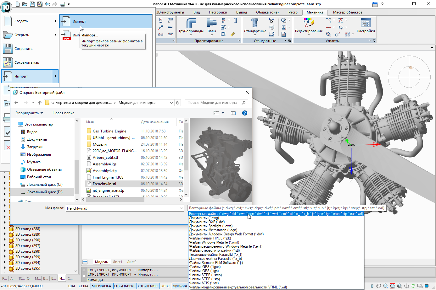
Fig. 8. Import capabilities in nanoCAD Mechanics
A new 3D modeling module created on the basis of the C3D core from a Russian company C3D Labs and working in conjunction with nanoCAD Mechanics, provides new 3D modeling capabilities, as well as advanced export / import functionality in the most common formats: STL , IGES, STEP, WRL and others (Fig. 8 and 9). Now you can not only work with models prepared in other systems, but also, for example, print models created in nanoCAD Mechanics on 3D printers.
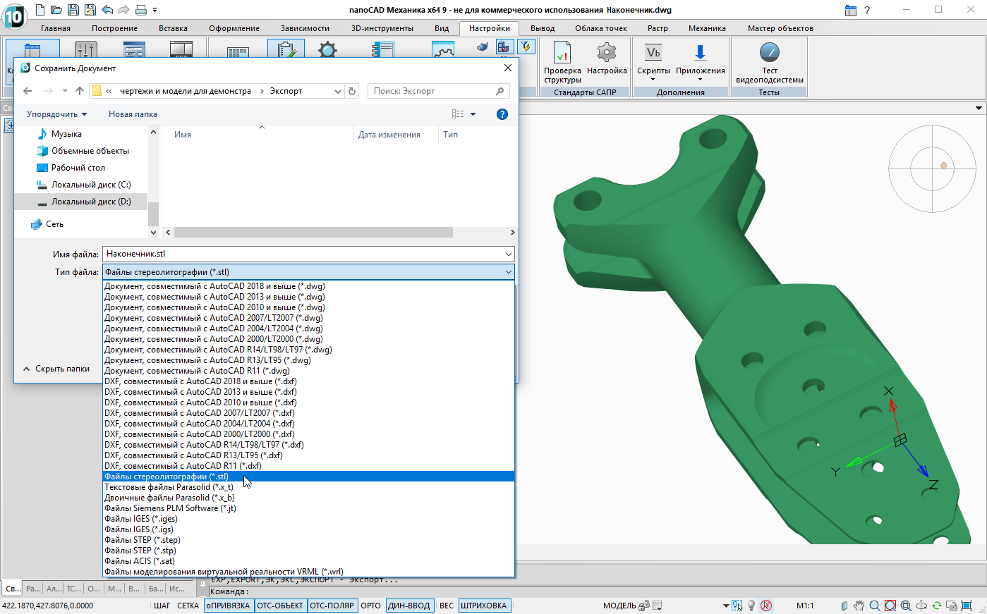
Fig. 9. Export to nanoCAD Mechanics
In addition, licensed users of nanoCAD Mechanics with a 3D module on a C3D engine receive a fully domestic solution, which in modern conditions is an important factor in the calm and confident development of business.
Boolean operations
Among other things, in the updated 3D-module appeared such a tool as logical or, in a different way, Boolean operations, including functions of subtraction, intersection and union. In some cases, this possibility significantly speeds up the work in the process of volumetric modeling.

Fig. 10. Boolean operations
Specification Editor
At the request of users in the new version two new specification templates have been added:
- a template of a built-in specification drawing that allows forming a table without stamps and placing it on any format (Fig. 11);
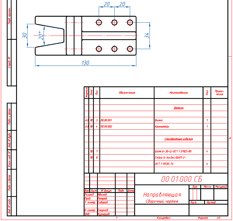
Fig. 11. Embedded specification in nanoCAD Mechanics
- The template of the plasma specification, allowing to form the specifications for forms 2 and 2a GOST 2.106-96 (Fig. 12).
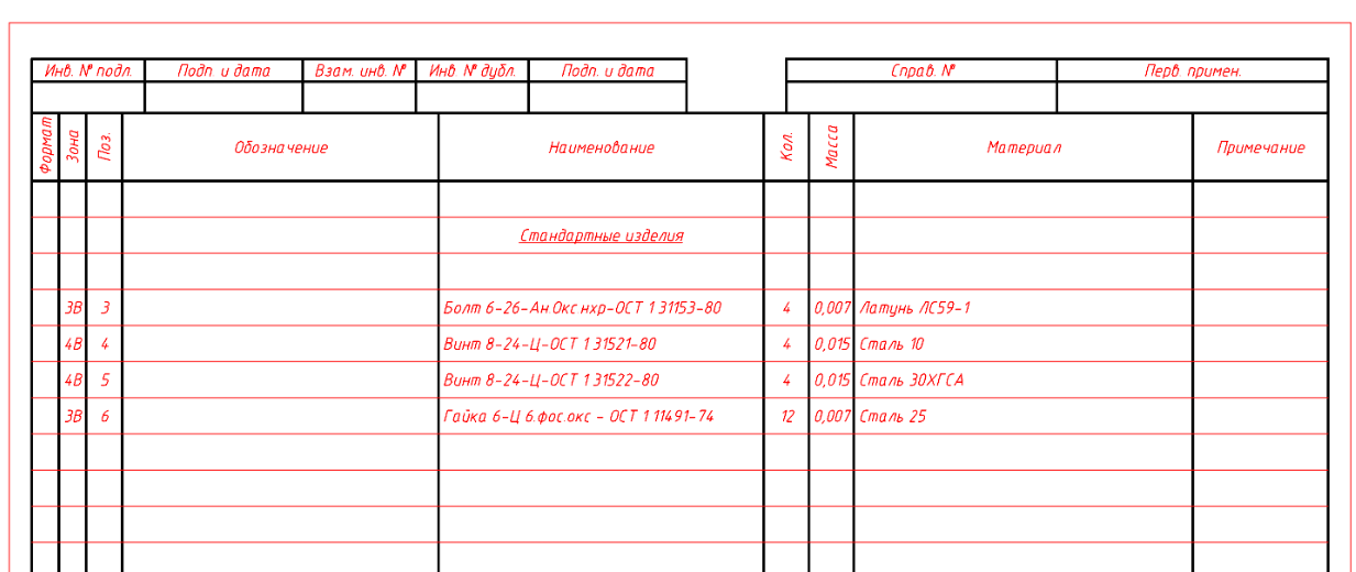
Fig. 12. Plasma specification in nanoCAD Mechanics
A special feature of the Plasma specification is the presence of additional columns “Mass” and “Material”. When using standard products from the nanoCAD Mechanics base, these columns are filled automatically - just like the “Name” column; All standard products fall into the appropriate section.
When forming group types of specifications, it became possible to create positions for the main performance. The quantity is automatically duplicated in the specification editor for all active versions of the object (Fig. 13).
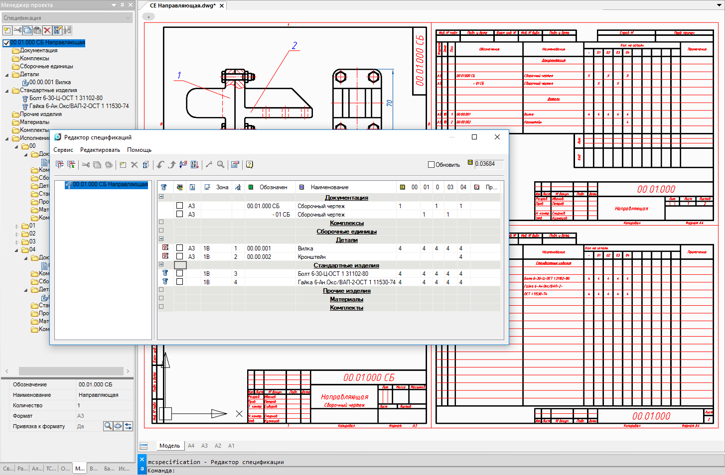
Fig. 13. New features for the formation of group specifications
New features to work with design elements
Universal Leader
Universal leaders can now be used to form complex specification callouts (Fig. 14). At the same time, it is possible to refer to positional callouts. If there are such links in the universal balloon, the user can, with one click of the mouse, move to the corresponding location in the drawing, where the desired object is located. This is especially useful when working with large drawings.
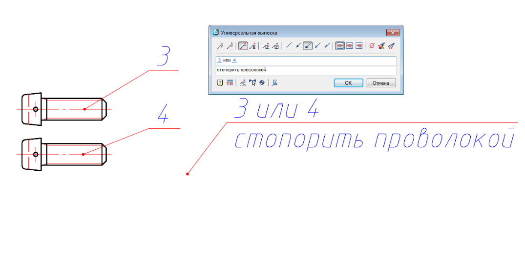
Fig. 14. Advanced Universal Leader Features
Roughness
There are new settings for the usual roughness (small height of the roughness sign, interline indent) and for unspecified roughness (upper shelf length, text indent below, text thickness). Due to this, the user can create various images of the corresponding symbol within the framework of GOST 2.309-73.
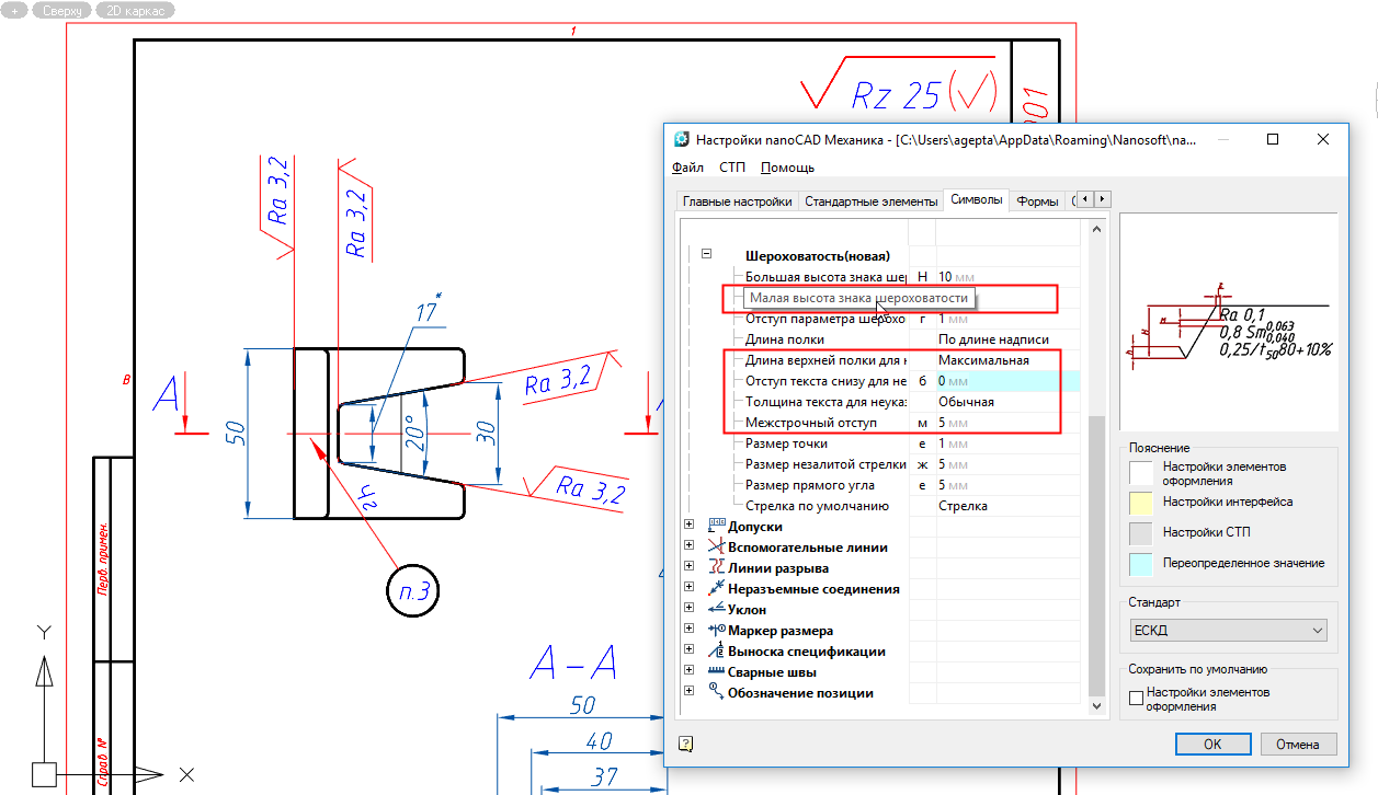
Fig. 15. New settings for the sign of roughness
Note that the roughness with the extension line can now be put in any direction (Fig. 15).
Technical requirements
The following features have been added to work with technical requirements:
- the possibility of strikethrough text in the technical requirements - this will help users to capture the changes that have appeared in the drawing;
- the ability to insert the symbol of the roughness in the text of the technical requirements.
In addition, in the line of the technical requirements editor there appeared the setting of the indent from the item number to the text, which allows to reduce and increase the corresponding indent (Fig. 16).
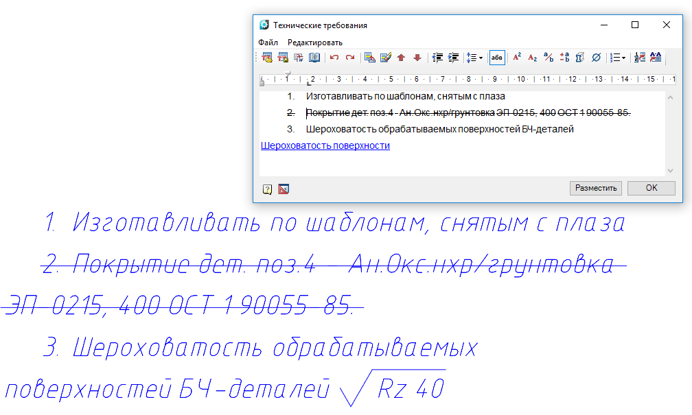
Fig. 16. New features when working with technical requirements
Catalogs of standard products
Aircraft fasteners (OST 1)
As already mentioned, the catalogs of standard products nanoCAD Mechanics are replenished with each new release. Several dozens of new elements of aviation fasteners (OST 1) were added to the base of the nanoCAD Mechanics 9.0 elements.
All of these standard products can be used to create bolted patterns.
The functionality of bolted connections, implemented in nanoCAD Mechanics, allows you to fasten packages of arbitrary thickness and with an arbitrary number of parts. When setting specification items, all fastener designations corresponding to the required OST automatically fall into the specification (Fig. 17).
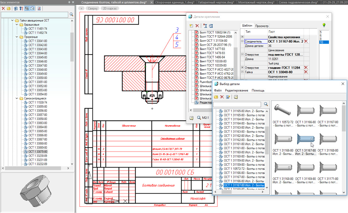
Fig. 17. Catalog of standard products nanoCAD Mechanics 9.0: aviation fasteners
In general, I would like to note that during the whole of 2018, the developers of nanoCAD Mechanics paid the most serious attention to working with the functionality required by the aircraft industry, primarily because of the fact that enterprises belonging to the United Aircraft Building Corporation (UAC) showed genuine interest to the program. Of course, much remains to be done in this direction, but with in-depth testing of the software product, users from the aircraft industry have formulated quite clear and distinct wishes, among which was the catalog of standard products according to OST 1, so necessary for aircraft designers.
Elements of pipeline fittings
The base of nanoCAD Mechanics 9.0 is replenished with elements of pipeline valves. All pipeline fittings have six types, they can display sections of the points of attachment. And they get to the specification as assembly units with the corresponding name (fig. 18).
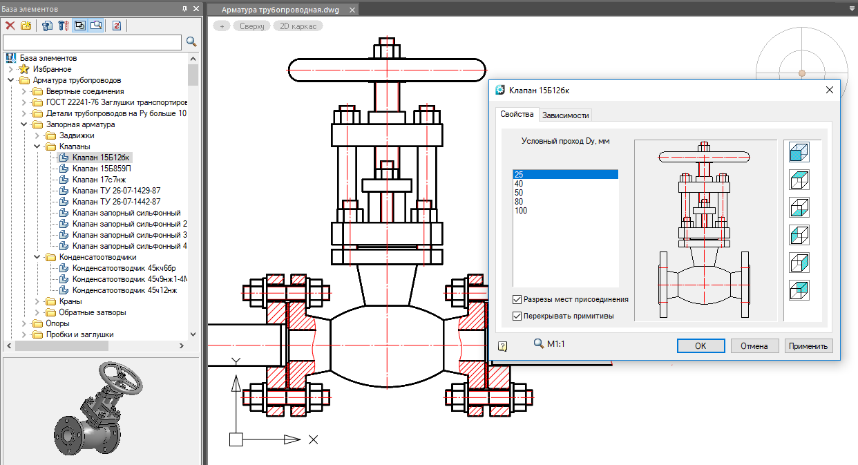
Fig. 18. Catalog of standard products nanoCAD Mechanics 9.0: pipe fittings
Flanges can be attached to the fittings with flanges according to the old standards of 1980 and the new standard GOST 33259-2015, the diameter and pressure are automatically selected.
Project development prospects
The development of 3D functionality and parametric modeling, as well as the continuous improvement of 2D tools, allow nanoCAD Mechanics to take a strong position in the computer-aided design market.
An open API and export / import capabilities make it possible to integrate it into almost any PDM / PLM system, providing end-to-end product design in the information environment. This is an important factor in creating a single information space at the enterprise, which is necessary for the development of modern production.
Summing up, it is worth noting that with the unconditional orientation of the nanoCAD Mechanics program on Russian users, its quality, functionality and relatively low price not only make it possible to successfully use this solution in the country, but also create good prerequisites for entering the world market.