August 16, 2016 at 12:41
How NetApp FAS Memory Works: NVRAM, Cache, and Tetris
In this article I want to consider the internal storage device of NetApp FAS storage and how it can assemble Tetris.

The storage memory of any NetApp FAS controller consists of memory modules that are used to read, write, and battery-powered caches, hence the “NV” prefix - Non Volatile MEMory / RAM / LOG. RAM is divided into the following functional parts: NVRAM, MBUF buffer (or system cache), which are discussed in more detail.

* Data dumping to disks occurs from MBUF, according to the event of fullness of NVRAM , and not from NVRAM itself.
In NVRAM, sequentially, like LOG records in a database, NVLOG records are collected, in their original form, as they were sent by the hosts. As soon as data from the host enters NVRAM, the host receives a record confirmation. After a CP event occurs that generates a flush of data from the MBUF to disks, followed by confirmation, the NVRAM is cleared. Thus, in a normally working storage system, the contents of NVRAM are never read, but only written, and when the space in it runs out, CP occurs and the NVRAM is cleared. Reading NVRAM occurs only after a failure.
In the High Availability (HA) pair, of the two NetApp FAS controllers, the NVRAM is always mirrored, each controller has a copy of its neighbor. This allows, in the event of a failure of one controller, to switch and further service all hosts to the surviving controller. After the CP event occurs (flushing data to the confirmation disk), the NVRAM is cleared.
To be more precise, each of these two parts is divided into two more parts, total 4 for HA pairs (i.e. 2 local). This is done so that when half of the local NVRAM is full, data reset does not inhibit new incoming commands. That is, while data is being reset from one part of the local NVRAM, new ones are already arriving in the second half of the local NVRAM.
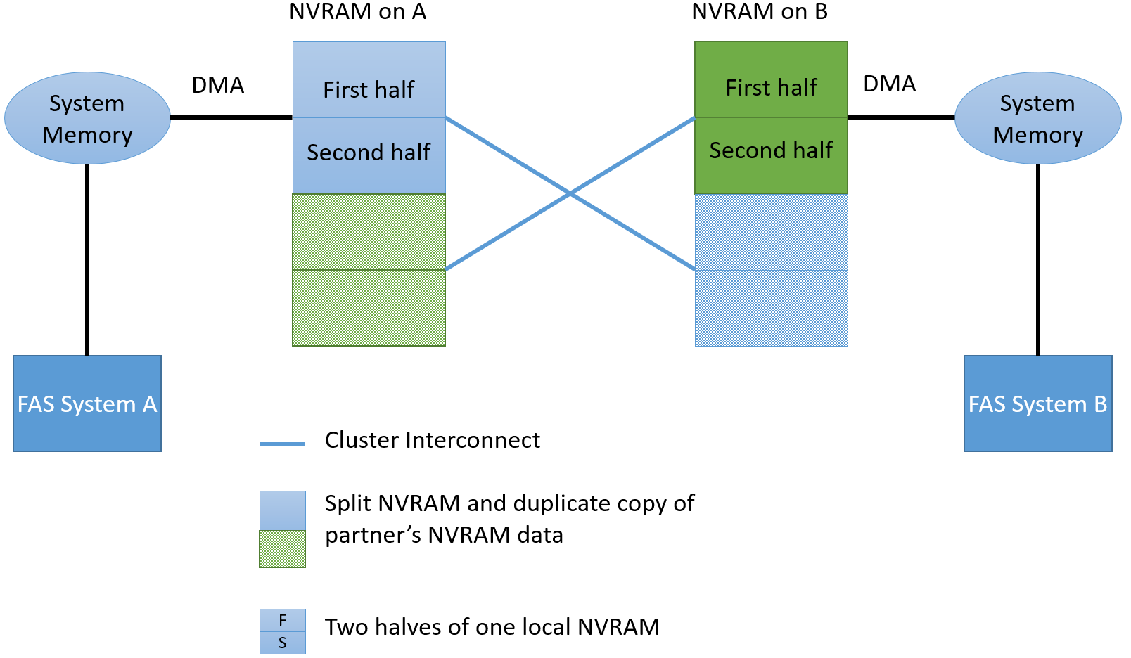
In order to protect data from Split-Brain in the MCC , the data that is written will be confirmed to the host only after it enters the NVRAM of one local controller, its neighbor and one remote neighbor (if the MCC consists of 4 nodes ) Synchronization between local controllers is performed via HA Interconnect (this is an external connection for dual-controller systems in two different chassis), and synchronization to a remote node is performed via FC-IV adapters (this is also an external connection). This scheme allows switching within the site if the second HA pair controller has survived, or switching to the second site if all the local storage nodes are out of order. Switching to the second site occurs in seconds.

It is important to note that NVRAM, on the one hand, is a technology that is not only armed with NetApp, but, on the other hand, is used by NetApp to store logs (hardware implementation of a journaling file system), while most other storage manufacturers use NVRAM at the “block level” (Disk Driver level or Disk Cache) for caching data in NVRAM - this is a big difference.
The presence of NVLOG allows NetApp FAS not to translate in a HA-pair, the only one controller left alive in Pass-Through mode (recording, without a cache, directly to disks) if one of them died. Let's dwell on this a bit and start with why do we need a write cache? A cache is needed to spoof hosts and speed up recording; it confirms the recording of data before the data actually gets to disks. Why even switch the controller to Pass-Through mode, if the cache has a battery, while all A-brands of storage have a cache mirroring in the HA pair? The answer is not easy to see at a glance, firstly, the HA mechanism ensures that the data is not damaged and is flushed to disks when one of the two controllers in the HA pair fails, and clients transparently switch to a partner, first second, the most important thing in this case, so that the data is not damaged at the level of the data structure of the storage system itself, this is worth dwelling in more detail. Recalculating check sums for RAID in memory is not a novelty for a long time, since it speeds up the disk subsystem, many if not all A-brands have mastered this trick, but it is data dumping from the cachein the form already processed at the RAID level, it leaves a chance of data corruption that cannot be tracked and repaired after restarting two controllers. So, in the event of a failure of the first, and then the second controller, it may turn out that it is impossible to track the integrity of the initially received data as a result of processing, that is, the data may be damaged, in other situations it is possible to track and repair the damage, but for this it is necessary to start checking the data structure of the storage system. Since the write cache becomes a cornerstone and a potential big problem, if one controller fails in an ON pair, most storage systems should go into PassThrough mode with direct burning to disks, turning off the write cache to eliminate the possibility of damage to their file structure.
On the other hand, most of these storage systems allow the administrator to manually put the surviving controller manually into record caching mode, but this is not safe, because if the second controller fails, the data at the level of the storage structure can be damaged and will have to be restored. sometimes this can lead to tragic consequences. Due to the fact that FAS systems store data in the form of logs, and not in the processed form after WAFL or RAID , and the data that has already been processed is reset in the form of rolling the CP system snapshot, in a single transaction, this allows you to completely bypass the probability of data corruption. So in many moderncompeting storage systems, when one controller in a HA pair dies, not only does the load from the deceased controller fall on the second, it also disconnects its cache to optimize records, which greatly degrades the speed of work in such situations. This is done so that the data being written is exactly written in the undamaged form to the disks, and most importantly, the file structure of the storage system remains intact. Some do not bother with this issue at all and just honestly write about this “nuance” in their documentation. And some are trying to get around this problem with the help of a “crutch”, offering to buy not a 2-node, but 4-node system at once. So, for example, the HP 3PAR system is arranged, where in case of failure of one controller, in the 4-node system, the remaining 3 controllers will work in normal recording mode, but in the event of a failure of 50% of the nodes, the system will go into Pass-Through mode. Sometimes there are funny situations when it is better for the entire storage system to die than for it to work with such terrible brakes. This contrasts with FAS systems, which even in single-mode configurations never disable the cache, as they are architecturally protected from such problems.
Writing, in fact, always occurs in MBUF (Write Memory Buffer). And from it, using a Direct Memory Access (DMA) request, NVRAM makes a copy of this data to itself, which saves CPU resources. After which the WAFL module selects the ranges of blocks to which data from MBUF will be written, this process is called Write Allocation. The WAFL module does not just select blocks thoughtlessly, but first collects the tetris (oh yes, Tetris! Have you not heard about it ? , then look at the 28th minute), and selects empty blocks, so that you can write the entire tetris to discs in one inextricable a piece.
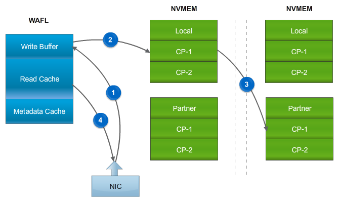
WAFL also performs other write optimizations for data. After the write confirmation from NVRAM arrives in the WAFL module, the data from the MBUF, according to the allocated blocks, is processed by the RAID module, where the checksum for the parity disks is calculated and the checksum is calculated, which is stored with each block (Block / Zone checksum). It is also important to note that the data from the MBUF transferred to the RAID module is “unpacked”, for example, some commands may request a record of a repeated pattern of information blocks or a request to move blocks, such commands by themselves do not take up much space in NVRAM, but when “unpacking” generate a lot of new data.
This is part of WAFL, which has undergone significant changes from its original device architecture, especially in terms of working with new storage media and parallelization (the new architecture began shipping in 2011) and prepared a bridgehead for the use of new storage technologies that may appear in the near future. Thanks to the intelligence of its device, Write Allocation allows you to granularly write data in different ways and to different places on the disk subsystem. Each separate stream of recorded information is processed separately and can be processed, depending on how the data is written, read, the size of the block and the nature of the record (and others). Based on the nature of the recorded data, WAFL can decide on what type of media it is worth writing and in which way. An example of this is Flash drives, where it makes sense to write with granularity and along the boundaries of the block along which the cells are erased (erase block size). In addition, meta information, which usually takes up much less space compared to the data itself, can be placed separately from large blocks with useful data, in some cases it has great benefit, which was established experimentally. In fact, the description of the Write Allocation internal device is a separate, very large topic. in some cases, it is of great benefit, which was established experimentally. In fact, the description of the Write Allocation internal device is a separate, very large topic. in some cases, it is of great benefit, which was established experimentally. In fact, the description of the Write Allocation internal device is a separate, very large topic.
From the WAFL module, data is transferred to the RAID module, which processes and writes them in a single transaction, striping to disks, including parity disks. And since the data is always written in stripe and always in a new place, the data for the parity disks do not need to be recounted, they have already been prepared in advance for recording by the RAID module. Due to this, in practice, in FAS systems, parity disks are always much less loadedthan the rest of the drives, which is in stark contrast to the regular RAID 4/6 implementation. It is also worth noting that the calculation of the check amount is performed immediately for the entire strip of recorded data, never overwriting the data (recording occurs at a new location), only the meta-information changes (links to new blocks with data). This leads to the fact that in the event of rewriting on one of the disks, it is not necessary to read information from the remaining disks into memory each time and recount the check sum, due to which system memory is used more rationally. Learn more about RAID-DP .

Tetris is a write and read optimization mechanism that collects data between CP (CP Time Frame) into chains of sequences of blocks from one host, turning small blocks into larger sequential records (IO-reduction). On the other hand, this allows read-ahead data to be enabled without complex logic. So, for example, there is no difference - read 5KB, or 8KB, 13KB or 16KB, etc. This logic is used for read-ahead. Read-ahead is a form of caching of data that could potentially be requested in the future, followed by the data that was just requested. And when the question becomes, which “extra” blocks should be read proactively for transfer to the cache, with Tetris, you automatically get the answer to this question: those that were recorded along with the requested data.

System Cache (MBUF) is used for both write and read operations. All read operations, without exception, fall into the cache, and just read data is read from it. When the storage processor cannot find the data in the system cache, it accesses the disks, and the first thing it does is put it in the cache for reading, and then give it to the host. Further, this data can be either simply deleted (the same read cache, everything is on disks anyway) or moved to a lower level (cache level II), if any: FlashPool (SSD disks, read-write cache) or FlashCache ( PCIe Flash card, read cache only). Firstly, the system cache, both the first and second levels, is crowded out very granularly: i.e. a 4 KB block of information may be superseded. Secondly, the system and level II cache, it is deduplication-aware, i.e. if such a block is duplicated or cloned, it will not be copied again and occupy memory space. It is essentialimproves performance by increasing cache hit. This happens when the set of data lying on the storage system can be well duplicated or cloned many times , for example, in a VDI environment.
Like many modern file systems, WAFL is a journaling file system. Like any journaling file system, a journal with log entries is used to ensure consistency and its integrity at the level of storage. While all other implementations of journaled file systems are designed in such a way that they can roll back to a consistent state in case of damage (it is necessary to perform verification and recovery) and try to recover, WAFL is designed in such a way that, in case of a sudden failure of the controllers, the damage itself is prevented. This is achieved due, firstly, to the atomicity of the Consistency Point recording, and secondly, due to the use of system snapshots during recording operations.
NetApp's snapshot technology has proven so successful that it is used everywhere in ONTAP as a basis for many other features and functions. Let me remind you that CP contains data already processed by WAFLand RAID. CP is also a snapshot, which before dumping the contents from the system memory (after processing by WAFL and RAID modules), the storage system removes the system snapshot from the unit and appends new data to the disks, then the storage indicates that the data was successfully written, then clears NVLOG entries in NVRAM. Before new data is flushed to disks (always to a new place), a system snapshot is taken, after which the data is either written in one transaction or (in case of an accident) the previously created snapshot (at the unit level) is used as the latest working version of the file system, in case of a sudden restart of the storage system in the middle of the transaction. If an accident occurs and both controllers rebooted or lost power, the data from NVRAM will restore all the information and reset the data to the disks as soon as the controllers turn on again. If only one controller shuts down or reboots, then the second controller from the copy of NVLOG to NVRAM will immediately restore the data and write it down, it will even happen transparently for applications. When the data is successfully flushed to disks, the last CP block, based on the old root inode (snapshot), creates a new one, including links to old and new, just recorded data.
CP is an event that is automatically generated under one of several conditions:
By the way, the CP reset state, very often, can indirectly indicate what problems are in the operation of the storage system, for example, when you do not have enough spindles or they are damaged . Read more about working in an article on the Knowledge Base FAQ: Consistency Point .
As mentioned earlier, NVRAM is used in FAS systems as a storage of log records, and not a write cache, therefore its size in HDD and hybrid FAS systems is not as large as that of competitors. Simply increasing NVRAM is not necessary. Each system is designed so that it has enough resources to service the maximum supported number of spindles.
As already mentioned, the battery powers the system memory. But it also powers up the system Flash drive installed in the controller. In the event of a power failure, after that, the contents of the memory will be drained to the system Flash-drive, so the storage system can live for a very long time off. The restoration of contents to memory occurs automatically when starting storage. The battery lasts up to 72 hours, and therefore, if the power is restored during this time, the contents will remain in the cache and recovery from the system Flash-drive will not occur.
As mentioned earlier, WAFL always writes to a new place, it was done architecturally for many reasons, and one of them is the dumping of MBUF contents in the form of a snapshot. Indeed, otherwise, in the case of physical rewriting of blocks - new, over old ones, with an incomplete cache reset transaction, this could lead to data corruption. It turned out that the “write to a new place” approach is very successful not only for spinning disks, and the snapshot mechanism, but also for Flash technologies, because of the need to uniformly dispose of all the cells of the SSD drives.
NetApp FAS RAM not only accelerates read and write operations, but is also architecturally designed to provide high reliability, speed and optimization for such operations. Rich functionality, multiple degrees of protection and the speed of the system cache qualitatively distinguish A-class systems for high productive loads and mission-critical tasks.
English translation of
How memory works in ONTAP:
This may contain links to Habra articles that will be published later .
Please send messages about errors in the text to the LAN .
Comments, additions and questions on the opposite article, please comment .
System memory
The storage memory of any NetApp FAS controller consists of memory modules that are used to read, write, and battery-powered caches, hence the “NV” prefix - Non Volatile MEMory / RAM / LOG. RAM is divided into the following functional parts: NVRAM, MBUF buffer (or system cache), which are discussed in more detail.
* Data dumping to disks occurs from MBUF, according to the event of fullness of NVRAM , and not from NVRAM itself.
NVRAM & NVLOG
In NVRAM, sequentially, like LOG records in a database, NVLOG records are collected, in their original form, as they were sent by the hosts. As soon as data from the host enters NVRAM, the host receives a record confirmation. After a CP event occurs that generates a flush of data from the MBUF to disks, followed by confirmation, the NVRAM is cleared. Thus, in a normally working storage system, the contents of NVRAM are never read, but only written, and when the space in it runs out, CP occurs and the NVRAM is cleared. Reading NVRAM occurs only after a failure.
NVRAM in HA
In the High Availability (HA) pair, of the two NetApp FAS controllers, the NVRAM is always mirrored, each controller has a copy of its neighbor. This allows, in the event of a failure of one controller, to switch and further service all hosts to the surviving controller. After the CP event occurs (flushing data to the confirmation disk), the NVRAM is cleared.
To be more precise, each of these two parts is divided into two more parts, total 4 for HA pairs (i.e. 2 local). This is done so that when half of the local NVRAM is full, data reset does not inhibit new incoming commands. That is, while data is being reset from one part of the local NVRAM, new ones are already arriving in the second half of the local NVRAM.
NVRAM at MCC
In order to protect data from Split-Brain in the MCC , the data that is written will be confirmed to the host only after it enters the NVRAM of one local controller, its neighbor and one remote neighbor (if the MCC consists of 4 nodes ) Synchronization between local controllers is performed via HA Interconnect (this is an external connection for dual-controller systems in two different chassis), and synchronization to a remote node is performed via FC-IV adapters (this is also an external connection). This scheme allows switching within the site if the second HA pair controller has survived, or switching to the second site if all the local storage nodes are out of order. Switching to the second site occurs in seconds.
NVRAM & Pass-Through
It is important to note that NVRAM, on the one hand, is a technology that is not only armed with NetApp, but, on the other hand, is used by NetApp to store logs (hardware implementation of a journaling file system), while most other storage manufacturers use NVRAM at the “block level” (Disk Driver level or Disk Cache) for caching data in NVRAM - this is a big difference.
The presence of NVLOG allows NetApp FAS not to translate in a HA-pair, the only one controller left alive in Pass-Through mode (recording, without a cache, directly to disks) if one of them died. Let's dwell on this a bit and start with why do we need a write cache? A cache is needed to spoof hosts and speed up recording; it confirms the recording of data before the data actually gets to disks. Why even switch the controller to Pass-Through mode, if the cache has a battery, while all A-brands of storage have a cache mirroring in the HA pair? The answer is not easy to see at a glance, firstly, the HA mechanism ensures that the data is not damaged and is flushed to disks when one of the two controllers in the HA pair fails, and clients transparently switch to a partner, first second, the most important thing in this case, so that the data is not damaged at the level of the data structure of the storage system itself, this is worth dwelling in more detail. Recalculating check sums for RAID in memory is not a novelty for a long time, since it speeds up the disk subsystem, many if not all A-brands have mastered this trick, but it is data dumping from the cachein the form already processed at the RAID level, it leaves a chance of data corruption that cannot be tracked and repaired after restarting two controllers. So, in the event of a failure of the first, and then the second controller, it may turn out that it is impossible to track the integrity of the initially received data as a result of processing, that is, the data may be damaged, in other situations it is possible to track and repair the damage, but for this it is necessary to start checking the data structure of the storage system. Since the write cache becomes a cornerstone and a potential big problem, if one controller fails in an ON pair, most storage systems should go into PassThrough mode with direct burning to disks, turning off the write cache to eliminate the possibility of damage to their file structure.
On the other hand, most of these storage systems allow the administrator to manually put the surviving controller manually into record caching mode, but this is not safe, because if the second controller fails, the data at the level of the storage structure can be damaged and will have to be restored. sometimes this can lead to tragic consequences. Due to the fact that FAS systems store data in the form of logs, and not in the processed form after WAFL or RAID , and the data that has already been processed is reset in the form of rolling the CP system snapshot, in a single transaction, this allows you to completely bypass the probability of data corruption. So in many moderncompeting storage systems, when one controller in a HA pair dies, not only does the load from the deceased controller fall on the second, it also disconnects its cache to optimize records, which greatly degrades the speed of work in such situations. This is done so that the data being written is exactly written in the undamaged form to the disks, and most importantly, the file structure of the storage system remains intact. Some do not bother with this issue at all and just honestly write about this “nuance” in their documentation. And some are trying to get around this problem with the help of a “crutch”, offering to buy not a 2-node, but 4-node system at once. So, for example, the HP 3PAR system is arranged, where in case of failure of one controller, in the 4-node system, the remaining 3 controllers will work in normal recording mode, but in the event of a failure of 50% of the nodes, the system will go into Pass-Through mode. Sometimes there are funny situations when it is better for the entire storage system to die than for it to work with such terrible brakes. This contrasts with FAS systems, which even in single-mode configurations never disable the cache, as they are architecturally protected from such problems.
Memory Buffer: Write
Writing, in fact, always occurs in MBUF (Write Memory Buffer). And from it, using a Direct Memory Access (DMA) request, NVRAM makes a copy of this data to itself, which saves CPU resources. After which the WAFL module selects the ranges of blocks to which data from MBUF will be written, this process is called Write Allocation. The WAFL module does not just select blocks thoughtlessly, but first collects the tetris (oh yes, Tetris! Have you not heard about it ? , then look at the 28th minute), and selects empty blocks, so that you can write the entire tetris to discs in one inextricable a piece.
WAFL also performs other write optimizations for data. After the write confirmation from NVRAM arrives in the WAFL module, the data from the MBUF, according to the allocated blocks, is processed by the RAID module, where the checksum for the parity disks is calculated and the checksum is calculated, which is stored with each block (Block / Zone checksum). It is also important to note that the data from the MBUF transferred to the RAID module is “unpacked”, for example, some commands may request a record of a repeated pattern of information blocks or a request to move blocks, such commands by themselves do not take up much space in NVRAM, but when “unpacking” generate a lot of new data.
Write allocation
This is part of WAFL, which has undergone significant changes from its original device architecture, especially in terms of working with new storage media and parallelization (the new architecture began shipping in 2011) and prepared a bridgehead for the use of new storage technologies that may appear in the near future. Thanks to the intelligence of its device, Write Allocation allows you to granularly write data in different ways and to different places on the disk subsystem. Each separate stream of recorded information is processed separately and can be processed, depending on how the data is written, read, the size of the block and the nature of the record (and others). Based on the nature of the recorded data, WAFL can decide on what type of media it is worth writing and in which way. An example of this is Flash drives, where it makes sense to write with granularity and along the boundaries of the block along which the cells are erased (erase block size). In addition, meta information, which usually takes up much less space compared to the data itself, can be placed separately from large blocks with useful data, in some cases it has great benefit, which was established experimentally. In fact, the description of the Write Allocation internal device is a separate, very large topic. in some cases, it is of great benefit, which was established experimentally. In fact, the description of the Write Allocation internal device is a separate, very large topic. in some cases, it is of great benefit, which was established experimentally. In fact, the description of the Write Allocation internal device is a separate, very large topic.
RAID
From the WAFL module, data is transferred to the RAID module, which processes and writes them in a single transaction, striping to disks, including parity disks. And since the data is always written in stripe and always in a new place, the data for the parity disks do not need to be recounted, they have already been prepared in advance for recording by the RAID module. Due to this, in practice, in FAS systems, parity disks are always much less loadedthan the rest of the drives, which is in stark contrast to the regular RAID 4/6 implementation. It is also worth noting that the calculation of the check amount is performed immediately for the entire strip of recorded data, never overwriting the data (recording occurs at a new location), only the meta-information changes (links to new blocks with data). This leads to the fact that in the event of rewriting on one of the disks, it is not necessary to read information from the remaining disks into memory each time and recount the check sum, due to which system memory is used more rationally. Learn more about RAID-DP .
Tetris performs IO-reduction
Tetris is a write and read optimization mechanism that collects data between CP (CP Time Frame) into chains of sequences of blocks from one host, turning small blocks into larger sequential records (IO-reduction). On the other hand, this allows read-ahead data to be enabled without complex logic. So, for example, there is no difference - read 5KB, or 8KB, 13KB or 16KB, etc. This logic is used for read-ahead. Read-ahead is a form of caching of data that could potentially be requested in the future, followed by the data that was just requested. And when the question becomes, which “extra” blocks should be read proactively for transfer to the cache, with Tetris, you automatically get the answer to this question: those that were recorded along with the requested data.
Read cache
System Cache (MBUF) is used for both write and read operations. All read operations, without exception, fall into the cache, and just read data is read from it. When the storage processor cannot find the data in the system cache, it accesses the disks, and the first thing it does is put it in the cache for reading, and then give it to the host. Further, this data can be either simply deleted (the same read cache, everything is on disks anyway) or moved to a lower level (cache level II), if any: FlashPool (SSD disks, read-write cache) or FlashCache ( PCIe Flash card, read cache only). Firstly, the system cache, both the first and second levels, is crowded out very granularly: i.e. a 4 KB block of information may be superseded. Secondly, the system and level II cache, it is deduplication-aware, i.e. if such a block is duplicated or cloned, it will not be copied again and occupy memory space. It is essentialimproves performance by increasing cache hit. This happens when the set of data lying on the storage system can be well duplicated or cloned many times , for example, in a VDI environment.
Consistency point
Like many modern file systems, WAFL is a journaling file system. Like any journaling file system, a journal with log entries is used to ensure consistency and its integrity at the level of storage. While all other implementations of journaled file systems are designed in such a way that they can roll back to a consistent state in case of damage (it is necessary to perform verification and recovery) and try to recover, WAFL is designed in such a way that, in case of a sudden failure of the controllers, the damage itself is prevented. This is achieved due, firstly, to the atomicity of the Consistency Point recording, and secondly, due to the use of system snapshots during recording operations.
NetApp's snapshot technology has proven so successful that it is used everywhere in ONTAP as a basis for many other features and functions. Let me remind you that CP contains data already processed by WAFLand RAID. CP is also a snapshot, which before dumping the contents from the system memory (after processing by WAFL and RAID modules), the storage system removes the system snapshot from the unit and appends new data to the disks, then the storage indicates that the data was successfully written, then clears NVLOG entries in NVRAM. Before new data is flushed to disks (always to a new place), a system snapshot is taken, after which the data is either written in one transaction or (in case of an accident) the previously created snapshot (at the unit level) is used as the latest working version of the file system, in case of a sudden restart of the storage system in the middle of the transaction. If an accident occurs and both controllers rebooted or lost power, the data from NVRAM will restore all the information and reset the data to the disks as soon as the controllers turn on again. If only one controller shuts down or reboots, then the second controller from the copy of NVLOG to NVRAM will immediately restore the data and write it down, it will even happen transparently for applications. When the data is successfully flushed to disks, the last CP block, based on the old root inode (snapshot), creates a new one, including links to old and new, just recorded data.
CP generating events
CP is an event that is automatically generated under one of several conditions:
- 10 seconds passed
- Half of NVRAM is full
- Local MBUF is full (High Water Mark). It is caused by the fact that one or several commands from the host generated a large amount of data for the CP, for example, recording a repeating pattern of a certain amount of information.
- Controller Stop Command (Halt)
- Others.
By the way, the CP reset state, very often, can indirectly indicate what problems are in the operation of the storage system, for example, when you do not have enough spindles or they are damaged . Read more about working in an article on the Knowledge Base FAQ: Consistency Point .
Why is NVRAM size not always important?
As mentioned earlier, NVRAM is used in FAS systems as a storage of log records, and not a write cache, therefore its size in HDD and hybrid FAS systems is not as large as that of competitors. Simply increasing NVRAM is not necessary. Each system is designed so that it has enough resources to service the maximum supported number of spindles.
Battery and Flash
As already mentioned, the battery powers the system memory. But it also powers up the system Flash drive installed in the controller. In the event of a power failure, after that, the contents of the memory will be drained to the system Flash-drive, so the storage system can live for a very long time off. The restoration of contents to memory occurs automatically when starting storage. The battery lasts up to 72 hours, and therefore, if the power is restored during this time, the contents will remain in the cache and recovery from the system Flash-drive will not occur.
SSD and WAFL
As mentioned earlier, WAFL always writes to a new place, it was done architecturally for many reasons, and one of them is the dumping of MBUF contents in the form of a snapshot. Indeed, otherwise, in the case of physical rewriting of blocks - new, over old ones, with an incomplete cache reset transaction, this could lead to data corruption. It turned out that the “write to a new place” approach is very successful not only for spinning disks, and the snapshot mechanism, but also for Flash technologies, because of the need to uniformly dispose of all the cells of the SSD drives.
conclusions
NetApp FAS RAM not only accelerates read and write operations, but is also architecturally designed to provide high reliability, speed and optimization for such operations. Rich functionality, multiple degrees of protection and the speed of the system cache qualitatively distinguish A-class systems for high productive loads and mission-critical tasks.
English translation of
How memory works in ONTAP:
- NVRAM / NVMEM (Part 1)
- NVRAM / NVMEM & Write-Through (Part 2)
- Write Allocation, Tetris, MBUF & CP (Part 3)
This may contain links to Habra articles that will be published later .
Please send messages about errors in the text to the LAN .
Comments, additions and questions on the opposite article, please comment .