Overview of the cloud controller TP-Link Omada OC200
This is our first version of the hardware wireless controller for the Omada EAP line. It implements support for access through the cloud, mobile application and network. And all this without paid licenses and monthly deductions. For remote network management, just connecting to our cloud is enough. In general, everything is as you like.
Under cat interface review plus a bunch of details on connecting, configuring and deploying.
With the words “wireless controller”, the imagination draws a bulky rack-mounted device as standard. It used to be. Previously, up to OC200 , a wireless network controller in a compact metal case with dimensions of 100x98x25 mm. Yes, it looks very tiny. But this is only by sight!
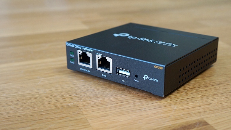
On the front panel there are two FE ports, two indicator lights, a USB host port and a recessed Reset button. One of the Fast Ethernet network interfaces allows not only transferring data, but also providing the device with power when connected to a switch supporting IEEE 802.3af or 802.3at. The power mode using PoE (Power over Ethernet) is more convenient, since it does not require laying additional wires and organizing outlets, in addition, the controller can always be reset remotely if necessary (of course, using a managed switch). The speed of the Fast Ethernet network interface (100 Mbit / s) is quite sufficient, since user traffic is not transmitted through it. But we will talk more about this in the next section.
The front panel USB interface is designed to connect a drive to which a local backup of the database and configuration files will be performed, it will also be required when connecting a large number of access points and / or wireless clients.

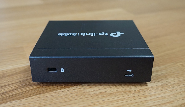
The Kensington lock and microUSB connector are located on the rear panel, which is needed to connect an external power source (5V / 1A), used in a situation where there is no possibility of powering the controller via PoE.
The TP-Link OC200 wireless controller is designed for desktop or wall mounting, so there are round rubber legs and L-shaped technological holes on its bottom panel. The compact size, low weight and lack of fans in the case allow you to place the device anywhere: in a rack or on a table, in a server room or on the wall of a regular office.

What's inside? Inside there is a system based on the Marvell Armada 88F3720 SoC processor with two ARMv8 cores operating at 1 GHz, as well as an Atheros AR8236 switch.

If for some reason a software solution is preferable to a hardware one or, for example, you will have more than 100 access points, you can use our TP-Link Omada Controller wireless network software controllerrunning Microsoft Windows and Linux operating systems.
Now let's look at the supported topologies.
In one of our previous materials, we have already described different options for connecting a wireless controller to a network. The OC200 has only two network interfaces. In addition, these are interfaces using Fast Ethernet technology. Does this mean that the controller will be a bottleneck, limiting the speed of all wireless clients? Definitely not! Of course, provided that the access points are not connected directly to the controller.
Modern wireless networks simultaneously support multiple SSIDs. Typically, each such network (SSID - Service Set Identifier) corresponds to a specific virtual network (VLAN) that exists in the core wire segments. This means that a trunk must be established between the switch and the access point, that is, a connection through which the traffic of several virtual networks can be transmitted simultaneously. Typically, IEEE 802.1P and 802.1Q protocols are used to organize the trunk. As a result, the access point will perform frame switching for all SSID / VLANs.
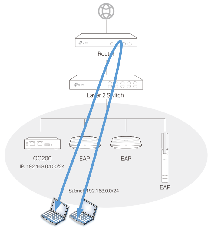
But how does the controller itself connect? Two ways. When using the first, the controller and access points are located on the same IP subnet (on the same virtual network). Perhaps it is worth noting that it is better to select a separate virtual network for communication between the controller and access points. The control traffic in the trunk between the switch and the access point is transmitted untagged, that is, the so-called native vlan is used. User traffic is usually tagged. An example of such a connection is shown in the figure below.

When connected in the second way, the access points and the controller are located in different IP subnets (in different virtual networks). An example of such a connection is presented below. A special case of such a connection will be the installation of the controller on a remote object.

Each of these methods has its advantages and disadvantages. So, for example, the first method requires minimal configuration, but at the same time all access points must be located in one extended virtual network. The second method is more flexible, but requires a bit more complicated setup. So, once again, we note that regardless of the way the OC200 controller is connected to the network, user traffic is not transmitted through it, so the Fast Ethernet interfaces that this model possesses will in no way limit users.
Perhaps a few words are worth mentioning about local switching. We decided to describe the obvious and present in the diagram the traffic paths for various connections of wireless clients. We take the connection of the controller and access points to the same subnet as the basis (we are talking exclusively about control interfaces).
Two clients connected to one access point and one wireless network (SSID). Traffic switching is carried out by means of the access point itself.

Two clients connected to the same wireless network, but to different access points. In this case, the traffic must be transmitted over the existing wired L2 infrastructure.

If wireless clients are connected to different access points and to different wireless networks, then in this case you cannot do without involving a router (a device of the third level of the OSI model). This is due to the fact that in a wired network, the traffic of such clients falls into different virtual networks between which routing can be performed.

And the last option: different wireless networks and one access point. In this case, the access point will not be able to perform switching on its own, since the clients are placed on different virtual networks - again, you will need to use a router.
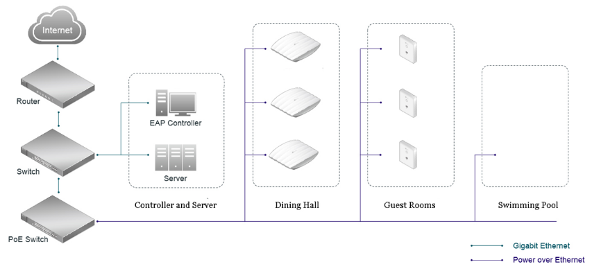
We would also like to acquaint readers with examples of the simplest network topologies used in various industries. Probably, one of the simplest schemes can boast catering, restaurants, cafes and so on.

Networks in stores and hotels are usually a little more complicated.

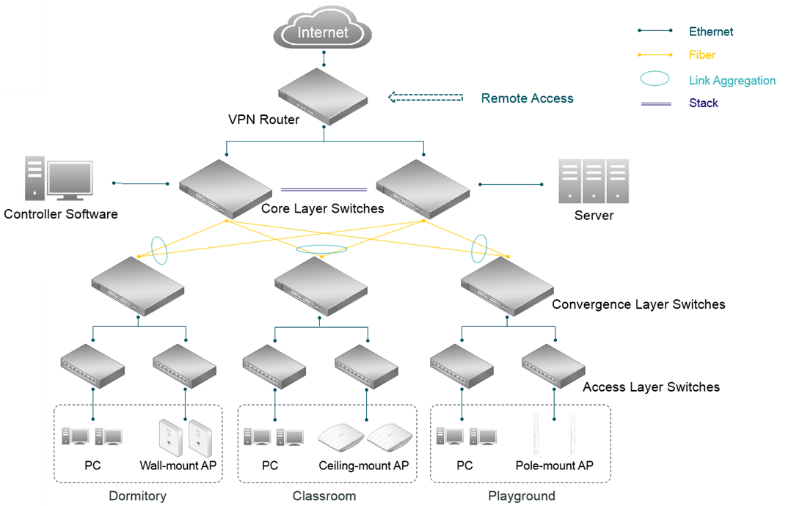
Local campus networks are perhaps the most complex.
Regardless of the complexity of the topology of the local network segment, the OC200 controller can be used to support the operation of a remote site. That is, for example, when you open a second store or cafe, you do not need to purchase an additional controller, since the access points of the second site can be controlled by an existing controller.

We hope that our brief description will help administrators correctly design the network taking into account all possible user traffic routes, so as to avoid bottlenecks as much as possible.
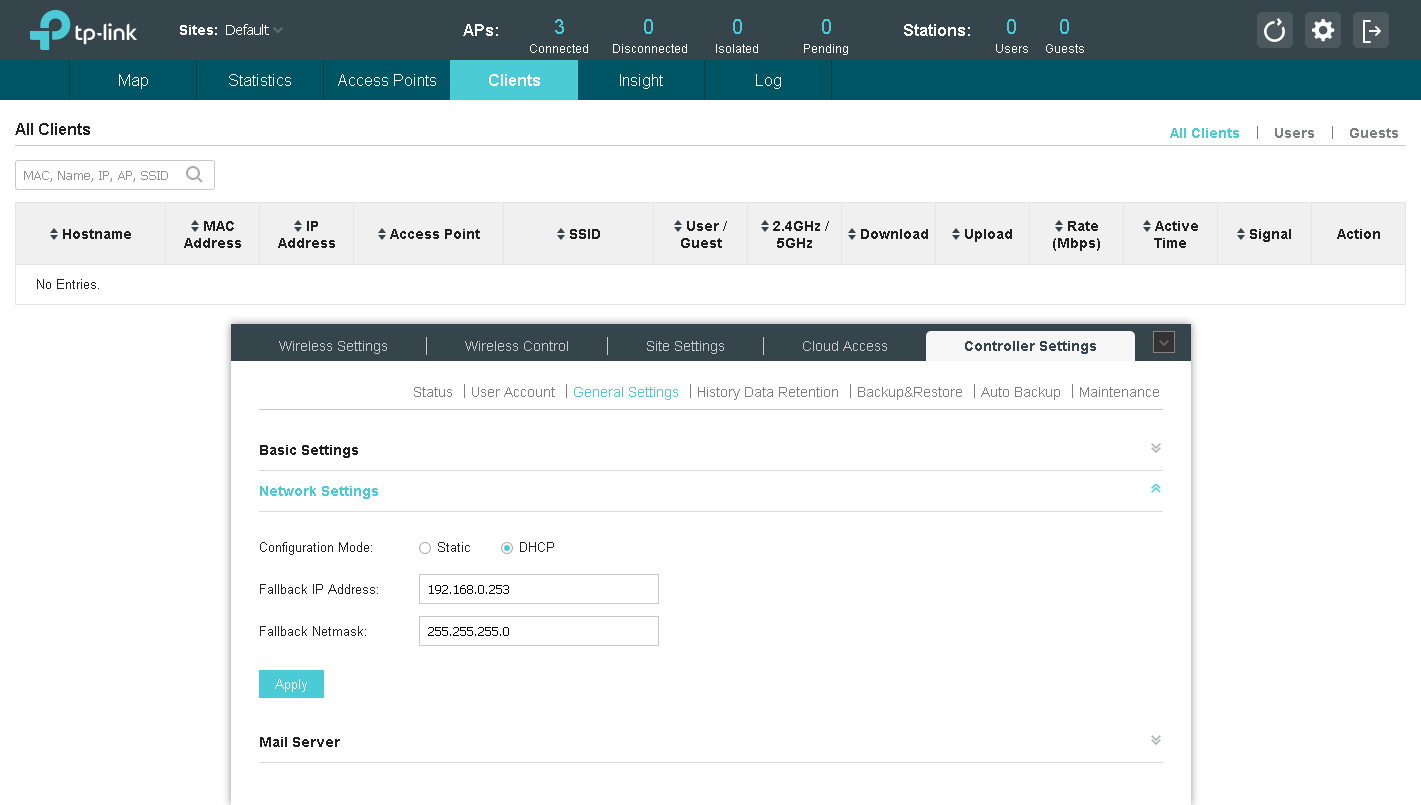
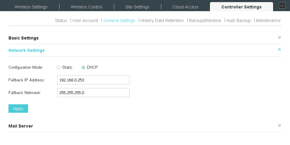
The TP-Link OC200 cloud-based wireless controller is configured to automatically receive IP parameters via DHCP. This means that no matter where he is connected, the administrator will immediately be able to access it. However, if for some reason there is no DHCP server on the network, OC200 will use the so-called fallback address, the default is 192.168.0.253. Naturally, if necessary, the administrator can configure a static IP address on the OC200.
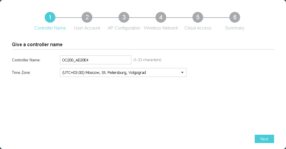
The first time you connect to the controller, the initial setup wizard automatically starts, with which you can fully prepare the wireless network for work in six simple steps. Since the OC200 controller is not interesting for administrators by itself, but in conjunction with the access points it supports, it is also necessary to connect access points to an existing wired network. Access points can be placed with the controller on the same IP network or in different ones, we wrote more about this in the section devoted to the consideration of possible topologies. Of course, access points can be added later - after the initial configuration of the controller is completed.

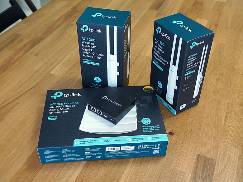
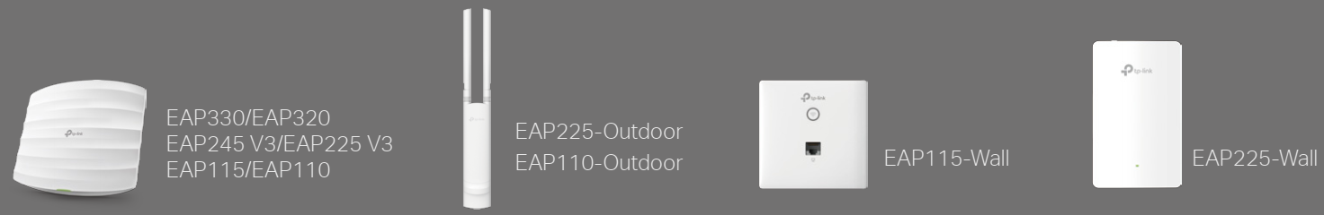
Speaking of access points. Currently, ten of our latest indoor and outdoor models are supported: EAP330, EAP320, EAP245 (October new), EAP225, EAP225-Outdoor, EAP115, EAP110, EAP110-Outdoor, EAP115-Wall, EAP225- Wall
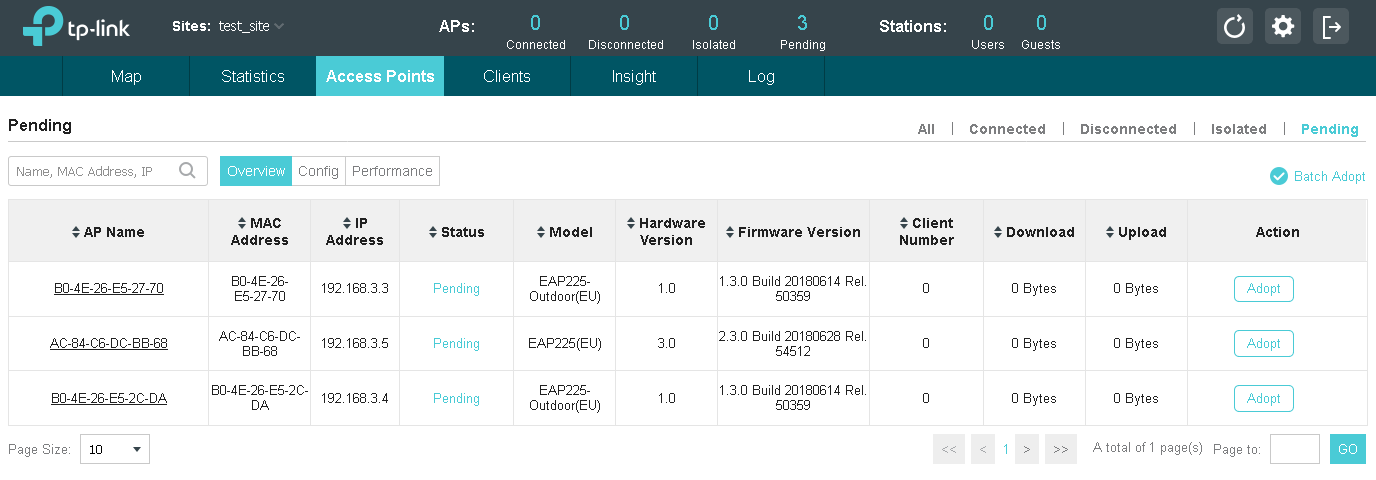
The controller automatically detects access points located in it on the same IP subnet. The administrator only needs to specify which devices need to be added to the network.
If the controller and access points are located in different IP subnets, then you can use one of the following methods to connect the points to the controller.
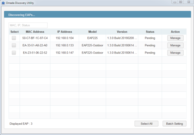
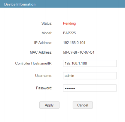
Connect to a subnet with access points of a computer or laptop with the pre-installed Omada Discovery utility. This utility allows you to detect wireless devices in the local segment and add them to the OC200 controller.
Unfortunately, this approach cannot be called scalable, since the administrator will need to connect to all segments where access points can be located.
Using option # 138 of the DHCP protocol. This option allows you to inform the access points of the IP address of the TP-Link OC200 wireless controller. Having received information about the location of the controller, the access points will begin the process of connecting to the latter, the administrator will only have to allow the connection of access points to the network.
We will describe the entire procedure for configuring the core network for connecting access points in more detail. The first thing to start is to create virtual networks on the switches. As an example, we will consider the TP-Link T2600G-28MPS switch. Virtual networks 8 and 9 will be used to bind to the SSID, while we created VLAN10 to manage access points.

The second step is to configure the interfaces to which the access points are connected, transferring them to trunk mode. We will leave the controlling virtual network on these interfaces without a tag.

It is time to create L3 interfaces for the corresponding virtual networks.

For each virtual network in which wireless users can be located, as well as for the control network, you need to create the appropriate DHCP pools.
The final step is to specify the IP address of the OC200 wireless controller in option field 138. You
can verify the correctness of the settings by requesting registration points from the access points to the controller.

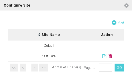
The initial configuration of the core network, controller and access points is completed. The only thing I would like to note is that the OC200 wireless network controller supports access points located on several sites (sites). In the case of using OC200 to build such a distributed wireless network, it will also be necessary to take care of the connectivity between the sites. Two methods for connecting remote access points to the controller are supported here.
The first, most obvious, is the organization of a site-to-site VPN connection between sites. With this connection, the controller and access points have the simplest configuration, since full IP connectivity between the networks of the head office and branches is ensured.
The second, slightly less obvious way is to use the virtual server function on the head office border router. This router performs port forwarding (PAT) inside the network, providing external access to the internal resources of the local network. In this case, in the branch networks, DHCP servers must be configured so that the value of option No. 138 is equal to the IP address of the WAN interface of the head office border router.
However, it seems to us that in most cases a tunnel connection between the head office and branches will nevertheless be realized, so the second method is extremely rare, although quite possible.
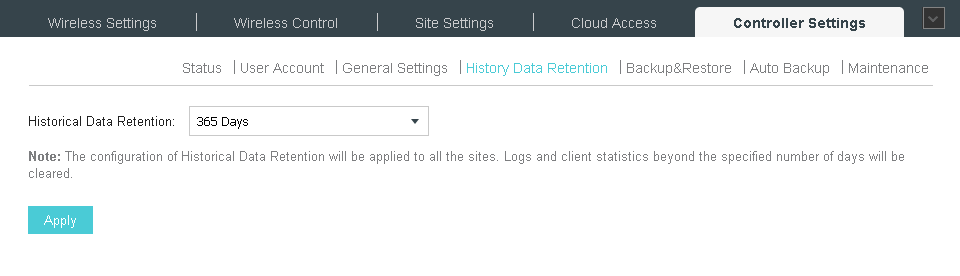
When performing maintenance on the wireless infrastructure, it is necessary to update the firmware for the equipment used on a regular basis. Updating should be done both for the controller itself and for the access points it controls. We will leave behind the scenes issues of updating the firmware of devices in a wired core network.
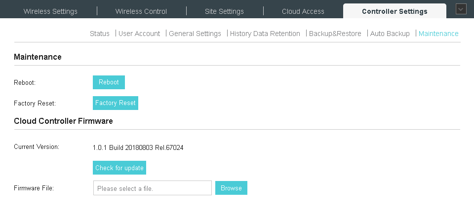
Controller firmware is changed using the Maintenance menu item on the Controller Settings tab. Updating can be done in manual or semi-automatic modes (in the latter case, the controller must be connected to the global network). When updating the controller manually, you only need to download the previously downloaded file with the new firmware onto it. The whole procedure takes several minutes and does not require any specialized knowledge from the administrator.

You also need to update the firmware of the access points. Since all access points are controlled from the controller, you must use the controller to update their firmware (Batch Upgrade menu of the Site Settings tab).

Access points of the same type are updated at the same time. This can also be done in manual or semi-automatic modes. When updating automatically, the controller will download the necessary file from our website and update it. The administrator will only have to wait for the completion of the process.

We usually post new firmware on automatic update servers with a slight delay; up to this point they are available only for manual download and update. Changing the firmware version in manual mode is a little more complicated than in semi-automatic mode: you just need to download the image from our website and upload it to the controller.

Even if your wireless network is working flawlessly at the moment, we still recommend periodically updating it, since the latest firmware versions may contain new functions or optimizations of existing ones, include support for new devices and technologies, and provide enhanced security.
One of the ways to control the wireless controller is the web interface, which can be connected using any modern browser.

A quick look at the options on the top menu. The Map menu, perhaps, provides the most visual information. With it, the administrator can indicate the location of existing access points on the plan, and the controller will show the estimated coverage area. I would like to emphasize that the intended coverage area is displayed, since in reality it is necessary to take into account many additional factors, such as materials of obstacles along the path of radio waves, the presence of interference sources, location of subscribers, and so on. When developing complex and responsible projects, a complete radio intelligence is indispensable.
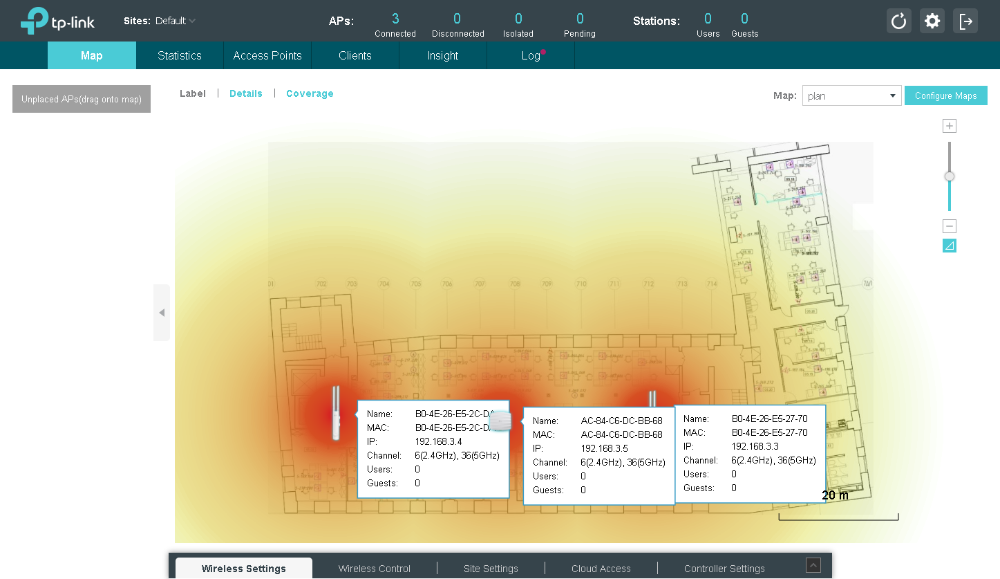
The TP-Link OC200 controller can be used to control the operation of access points in very large networks (up to 100 access points are supported (up to 50 recommended), geographically dispersed. The Omada Controller software solution, using the recommended platform configuration, supports up to 500 access points. For the convenience of administering distributed sites, the use of "sites" is recommended, which allows you to group devices by geographical feature.
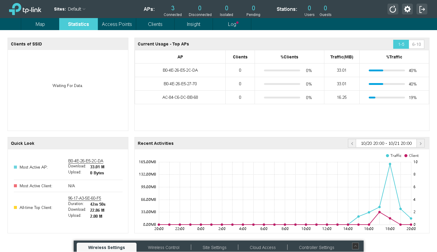
Statistical information about managed access points, the number of connected wireless clients, consumed traffic, and so on can be obtained using the Statistics menu.
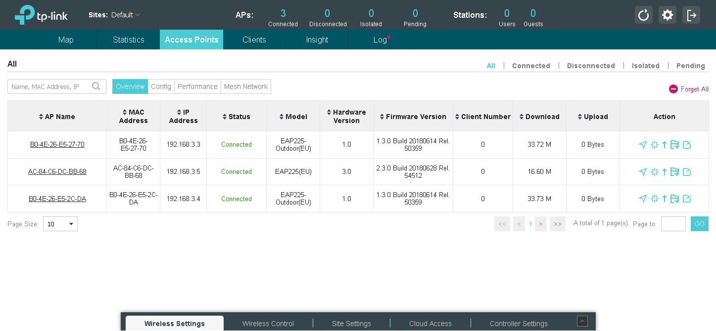
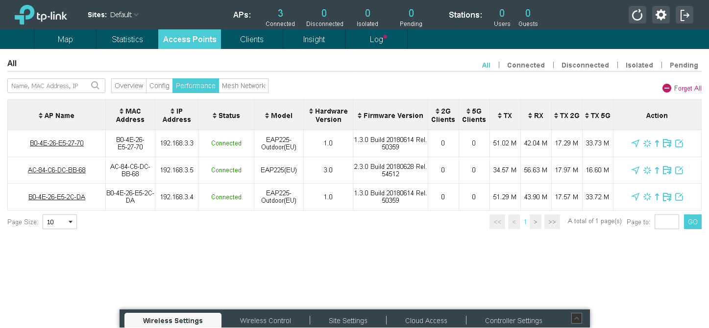
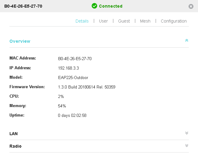
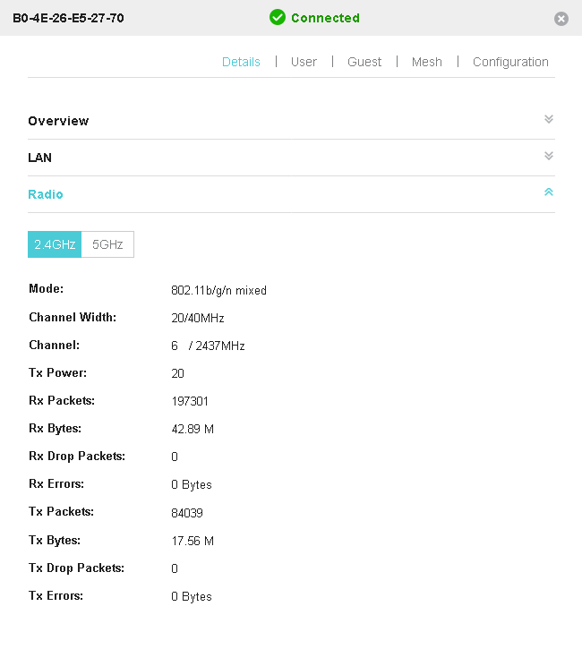
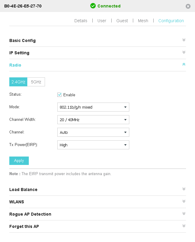
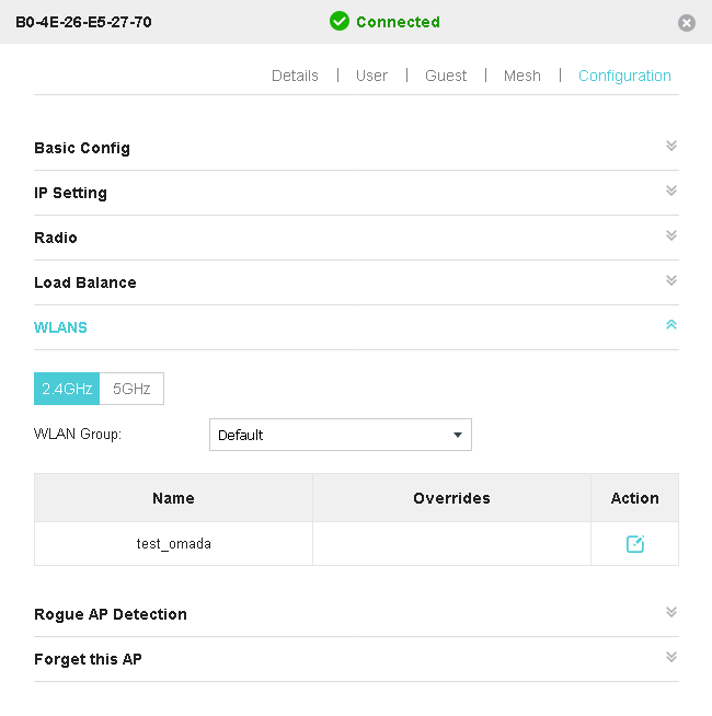
You can get more detailed information about a specific access point, as well as make its individual settings using the Access Points menu. So, for example, you can change the settings of the radio module, enable or disable the redistribution (balancing) of clients between access points and detection of unmanaged points, change the parameters supported by the point of wireless networks.


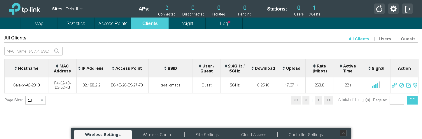
A list of connected wireless clients is available in the Clients menu.
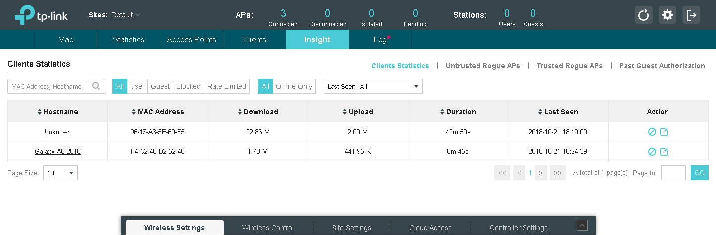
The Insight menu is also designed to display statistics, but only this time the statistics are displayed for wireless clients and all "foreign" access points that do not belong to our controller.

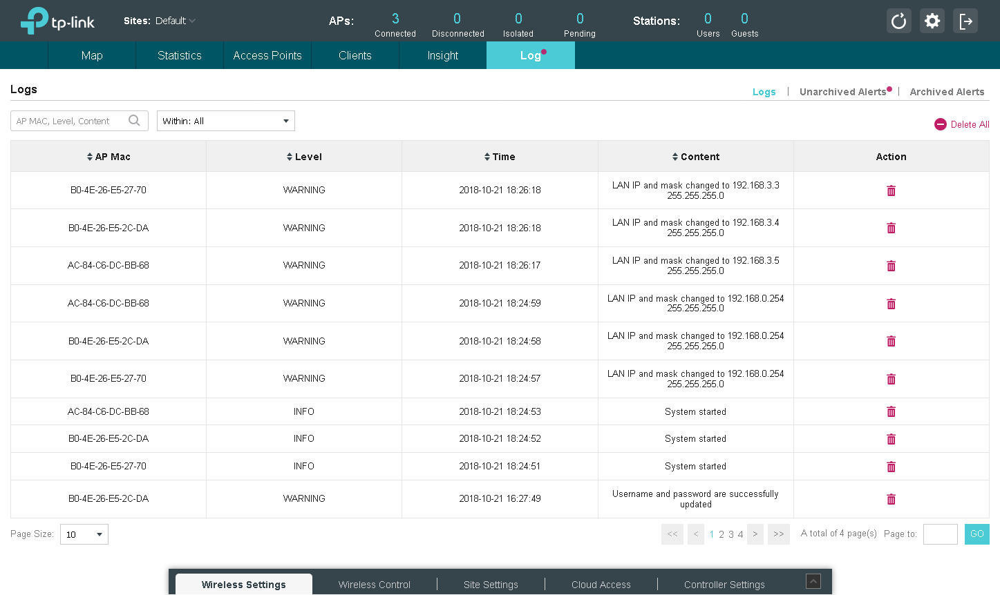
If you need access to the log information, refer to the Log menu.
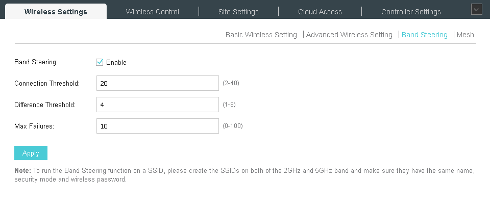
All global settings are made using the lower menu items. So, for example, the Wireless Settings item contains basic and advanced parameters of wireless networks, roaming control options, and mesh-network settings. It should be noted support for IEEE 802.11k / v standards for fast roaming. Support for IEEE 802.11r is on the way.


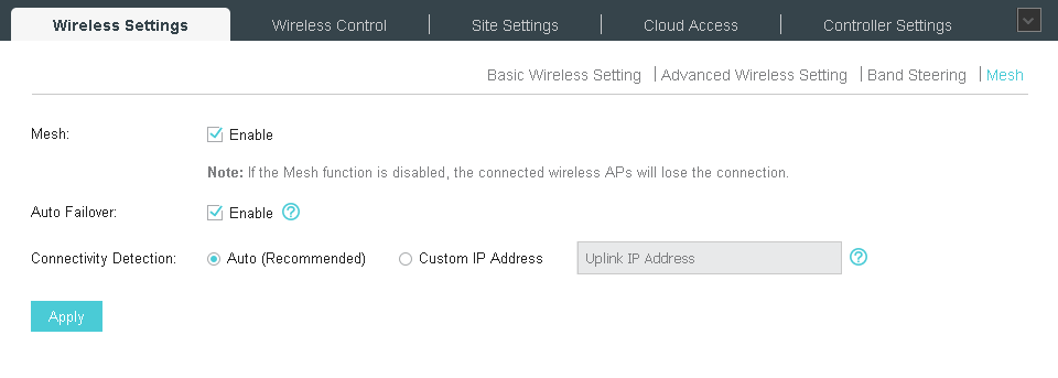
Mesh technologies make it possible to slightly change the standard approaches to building wireless networks. Now you can combine a wireless access point to a core network into a wireless segment. You can learn more about our implementation of mesh networks using the special page (https://www.tp-link.com/en/faq-2283.html) containing answers to frequently asked questions.
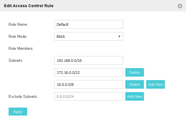
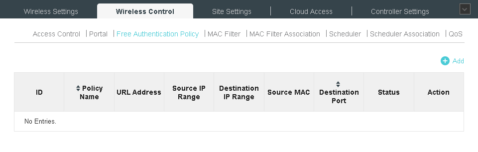
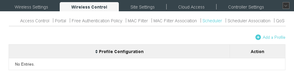
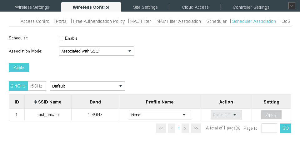
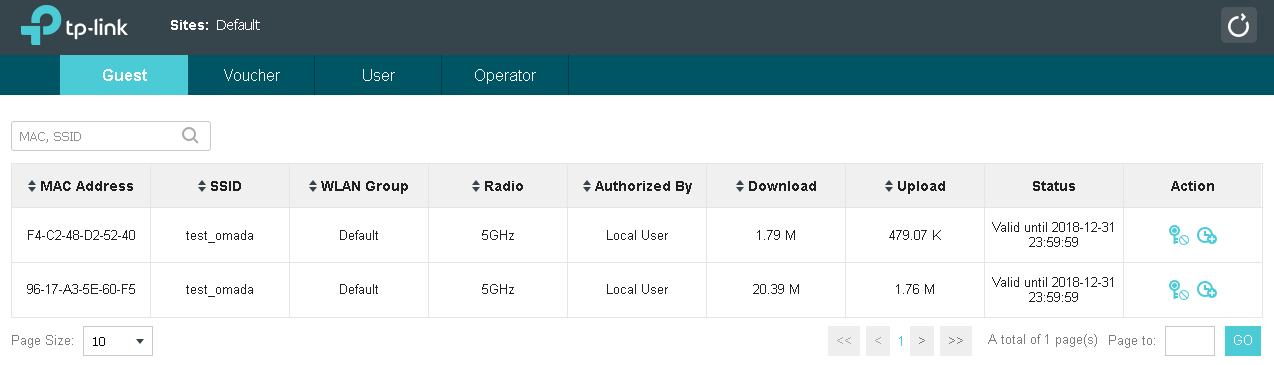
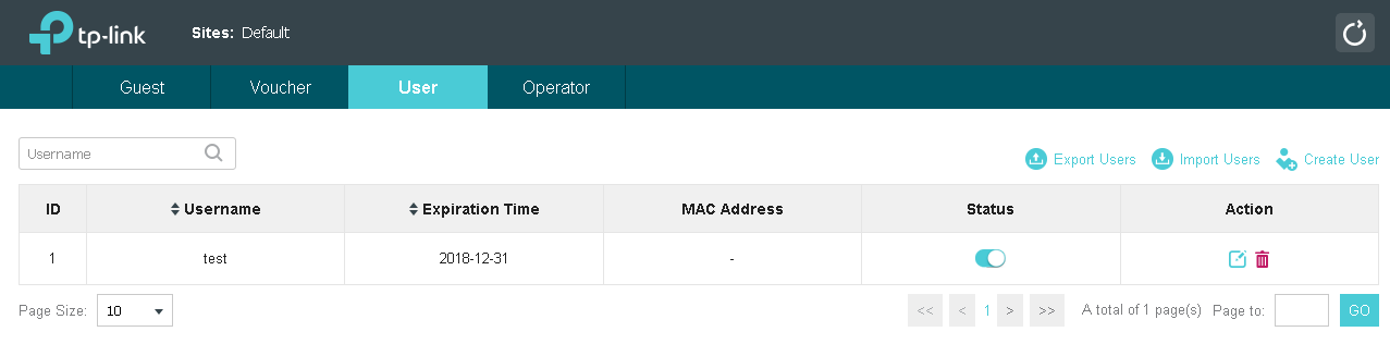
Wireless network access settings are controlled using the Wireless Control menu. Using this item, the administrator can create access lists that regulate traffic flows between specific subnets; perform filtering based on the MAC addresses of client devices, force users to undergo additional authentication on the captive portal, and configure quality of service settings.


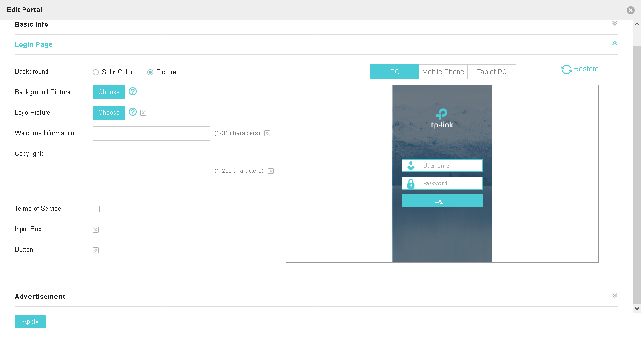


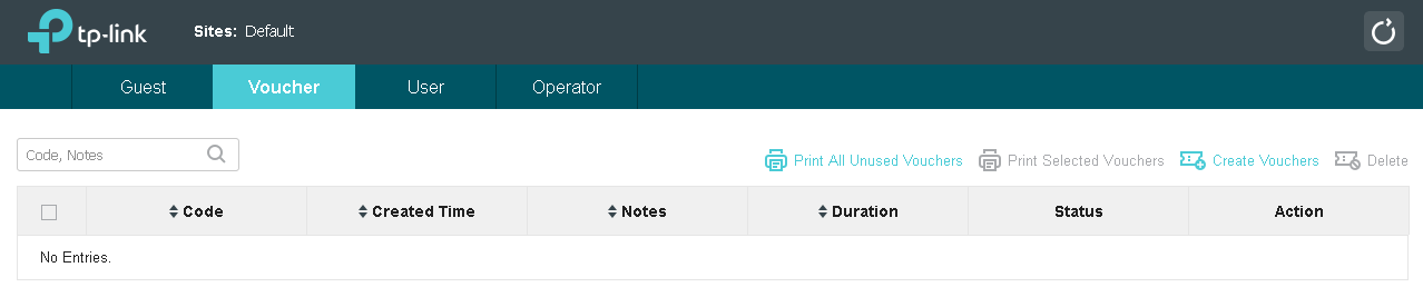
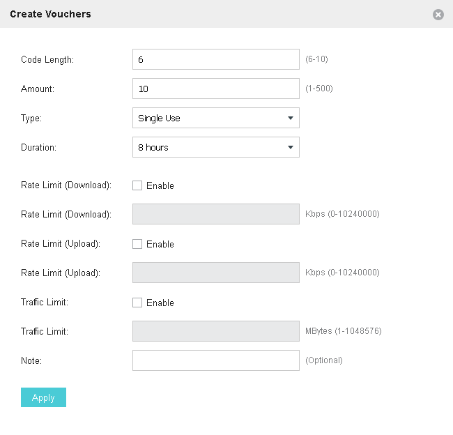
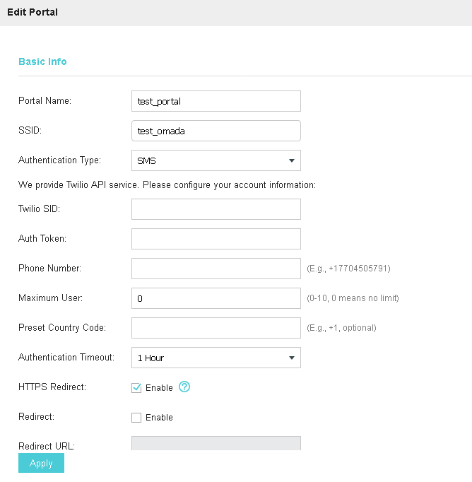
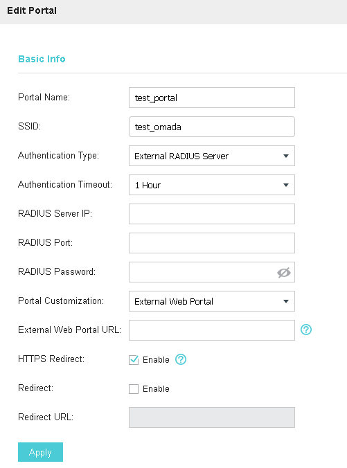
A couple of additional words need to be said about our captive portal. With its help, clients are authenticated using a password or a local user database, a remote RADIUS server or portal server, via SMS or using a Facebook account, voucher, or even without any additional authentication.


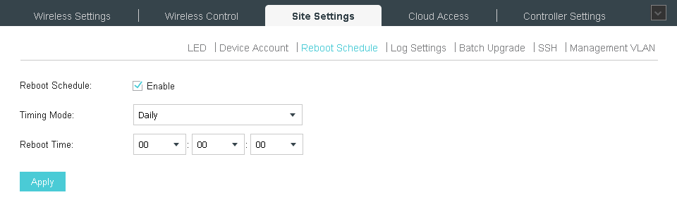
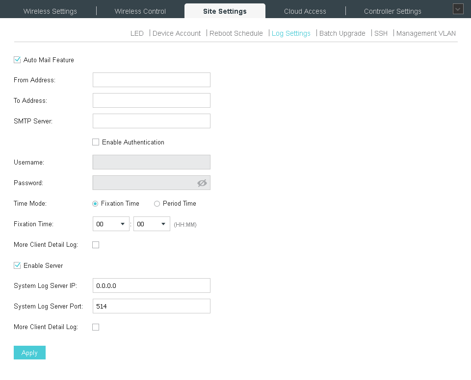
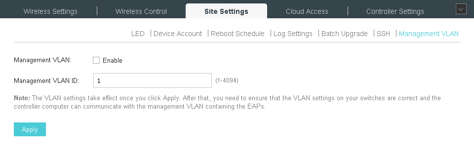
You can enable or disable the lights on devices using the Site Settings menu. Here you can also change the access settings for access points, set the reboot schedule, manage the settings for sending log information to remote servers, manage firmware, enable and disable access to the command line, change the virtual network number for management.

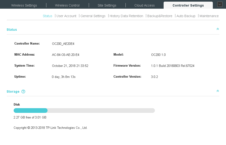
To control the OC200 controller itself, refer to the Controller Settings menu.


These are, perhaps, all the main points regarding the work with the web interface of the controller.
It is also worth saying a few words about the TP-Link Omada mobile application, which is ideal for remotely managing a company's wireless network. The administrator no longer needs to constantly carry a laptop with him, since all the necessary functions are also in the application developed for smartphones based on iOS and Android.


In addition, TP-Link Omada allows you to manage a wireless network not only with a local connection to the company’s network, but also using a cloud service, which is worth a closer look.

OC200 supports working with our cloud service, connecting to which will allow the administrator to perform remote configuration of equipment.
There are other remote control methods. So, for example, you can configure “port forwarding” on the company's border router so that incoming connections to a specific port are automatically broadcast inside the network to the controller address. Is this approach safe? Definitely not. Of course, you can configure additional rules on the corporate firewall that restrict the list of IP addresses from which you can connect, but we do not consider this the best solution.
Another way to remotely control your wireless network (more secure) is to use a VPN connection to your corporate network. When connecting using a VPN (for example, IPSec, OpenVPN, SSL, or even PPTP with MPPE), the administrator establishes a secure connection over which control traffic will be transmitted.
However, a simpler way to securely manage is to remotely connect using our cloud service. Consider the procedure for connecting the controller to the cloud.
There are two ways to connect. The first is to specify the cloud user credentials directly on the controller (Cloud Access tab).

If you do not have the required account yet, you can create one in a couple of minutes.

The second way is to add the controller directly from the cloud user’s personal account - you only need to specify the device key (of course, support for access from the cloud must be activated on the Cloud Access tab). The device key is located on a sticker on the bottom of the controller housing.
Regardless of the selected method of connecting the OC200 controller to the cloud service, information about the device will be available in the administrator’s personal account on our website.
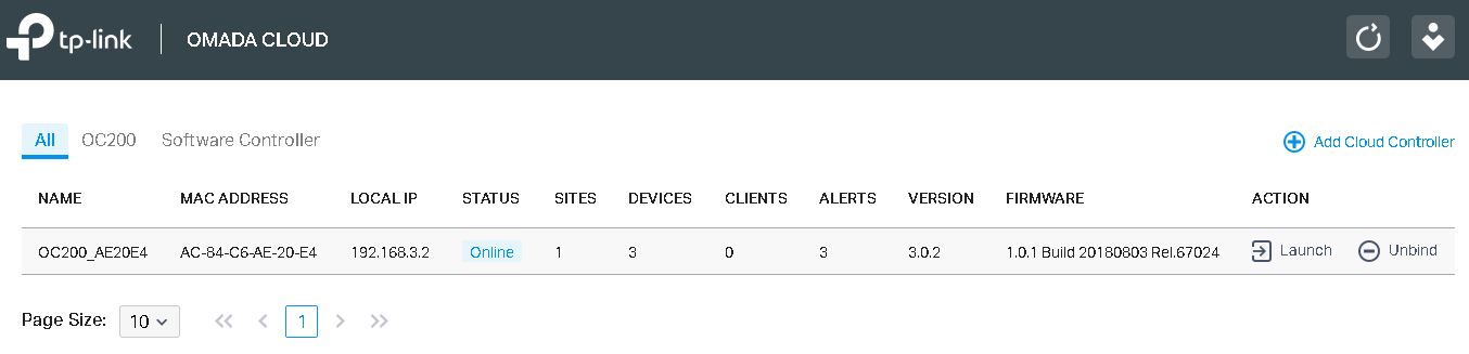
Now, to remotely control a wireless network, you just need to connect to our site using a mobile application or any modern browser, enter your personal account, and you can start managing it.
You can connect several controllers to the account of one cloud user, which will allow you to manage wireless networks of different departments or different companies from a single place.
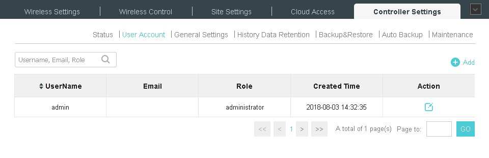
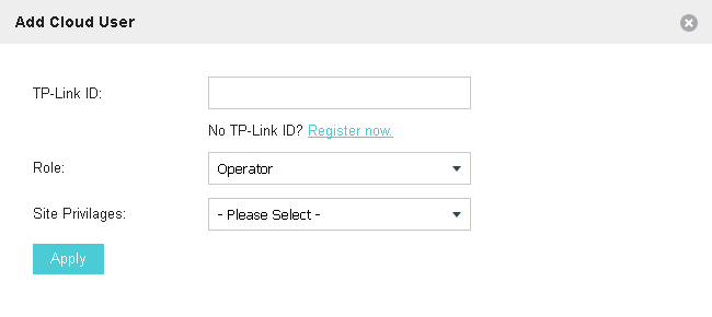
It is also worth noting that there is the possibility of remote control of the controller by several users with different access rights, you only need to add them to the device indicating the role of each account.
Remote control of the controller using a cloud service is possible not only using a web browser, but also using the TP-Link Omada mobile application.
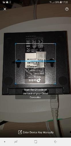
The association of the new OC200 wireless controller with a cloud user using a mobile application is even faster and easier: just scan the QR code located on the sticker on the controller’s case.
So, here's the bottom line:
Under cat interface review plus a bunch of details on connecting, configuring and deploying.
Hardware platform
With the words “wireless controller”, the imagination draws a bulky rack-mounted device as standard. It used to be. Previously, up to OC200 , a wireless network controller in a compact metal case with dimensions of 100x98x25 mm. Yes, it looks very tiny. But this is only by sight!
On the front panel there are two FE ports, two indicator lights, a USB host port and a recessed Reset button. One of the Fast Ethernet network interfaces allows not only transferring data, but also providing the device with power when connected to a switch supporting IEEE 802.3af or 802.3at. The power mode using PoE (Power over Ethernet) is more convenient, since it does not require laying additional wires and organizing outlets, in addition, the controller can always be reset remotely if necessary (of course, using a managed switch). The speed of the Fast Ethernet network interface (100 Mbit / s) is quite sufficient, since user traffic is not transmitted through it. But we will talk more about this in the next section.
The front panel USB interface is designed to connect a drive to which a local backup of the database and configuration files will be performed, it will also be required when connecting a large number of access points and / or wireless clients.
The Kensington lock and microUSB connector are located on the rear panel, which is needed to connect an external power source (5V / 1A), used in a situation where there is no possibility of powering the controller via PoE.
The TP-Link OC200 wireless controller is designed for desktop or wall mounting, so there are round rubber legs and L-shaped technological holes on its bottom panel. The compact size, low weight and lack of fans in the case allow you to place the device anywhere: in a rack or on a table, in a server room or on the wall of a regular office.
What's inside? Inside there is a system based on the Marvell Armada 88F3720 SoC processor with two ARMv8 cores operating at 1 GHz, as well as an Atheros AR8236 switch.
If for some reason a software solution is preferable to a hardware one or, for example, you will have more than 100 access points, you can use our TP-Link Omada Controller wireless network software controllerrunning Microsoft Windows and Linux operating systems.
Now let's look at the supported topologies.
Topologies
In one of our previous materials, we have already described different options for connecting a wireless controller to a network. The OC200 has only two network interfaces. In addition, these are interfaces using Fast Ethernet technology. Does this mean that the controller will be a bottleneck, limiting the speed of all wireless clients? Definitely not! Of course, provided that the access points are not connected directly to the controller.
Modern wireless networks simultaneously support multiple SSIDs. Typically, each such network (SSID - Service Set Identifier) corresponds to a specific virtual network (VLAN) that exists in the core wire segments. This means that a trunk must be established between the switch and the access point, that is, a connection through which the traffic of several virtual networks can be transmitted simultaneously. Typically, IEEE 802.1P and 802.1Q protocols are used to organize the trunk. As a result, the access point will perform frame switching for all SSID / VLANs.
But how does the controller itself connect? Two ways. When using the first, the controller and access points are located on the same IP subnet (on the same virtual network). Perhaps it is worth noting that it is better to select a separate virtual network for communication between the controller and access points. The control traffic in the trunk between the switch and the access point is transmitted untagged, that is, the so-called native vlan is used. User traffic is usually tagged. An example of such a connection is shown in the figure below.
When connected in the second way, the access points and the controller are located in different IP subnets (in different virtual networks). An example of such a connection is presented below. A special case of such a connection will be the installation of the controller on a remote object.
Each of these methods has its advantages and disadvantages. So, for example, the first method requires minimal configuration, but at the same time all access points must be located in one extended virtual network. The second method is more flexible, but requires a bit more complicated setup. So, once again, we note that regardless of the way the OC200 controller is connected to the network, user traffic is not transmitted through it, so the Fast Ethernet interfaces that this model possesses will in no way limit users.
Perhaps a few words are worth mentioning about local switching. We decided to describe the obvious and present in the diagram the traffic paths for various connections of wireless clients. We take the connection of the controller and access points to the same subnet as the basis (we are talking exclusively about control interfaces).
Two clients connected to one access point and one wireless network (SSID). Traffic switching is carried out by means of the access point itself.
Two clients connected to the same wireless network, but to different access points. In this case, the traffic must be transmitted over the existing wired L2 infrastructure.
If wireless clients are connected to different access points and to different wireless networks, then in this case you cannot do without involving a router (a device of the third level of the OSI model). This is due to the fact that in a wired network, the traffic of such clients falls into different virtual networks between which routing can be performed.
And the last option: different wireless networks and one access point. In this case, the access point will not be able to perform switching on its own, since the clients are placed on different virtual networks - again, you will need to use a router.
We would also like to acquaint readers with examples of the simplest network topologies used in various industries. Probably, one of the simplest schemes can boast catering, restaurants, cafes and so on.
Networks in stores and hotels are usually a little more complicated.
Local campus networks are perhaps the most complex.
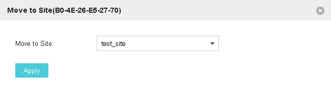
Regardless of the complexity of the topology of the local network segment, the OC200 controller can be used to support the operation of a remote site. That is, for example, when you open a second store or cafe, you do not need to purchase an additional controller, since the access points of the second site can be controlled by an existing controller.
We hope that our brief description will help administrators correctly design the network taking into account all possible user traffic routes, so as to avoid bottlenecks as much as possible.
Initial setup
The TP-Link OC200 cloud-based wireless controller is configured to automatically receive IP parameters via DHCP. This means that no matter where he is connected, the administrator will immediately be able to access it. However, if for some reason there is no DHCP server on the network, OC200 will use the so-called fallback address, the default is 192.168.0.253. Naturally, if necessary, the administrator can configure a static IP address on the OC200.
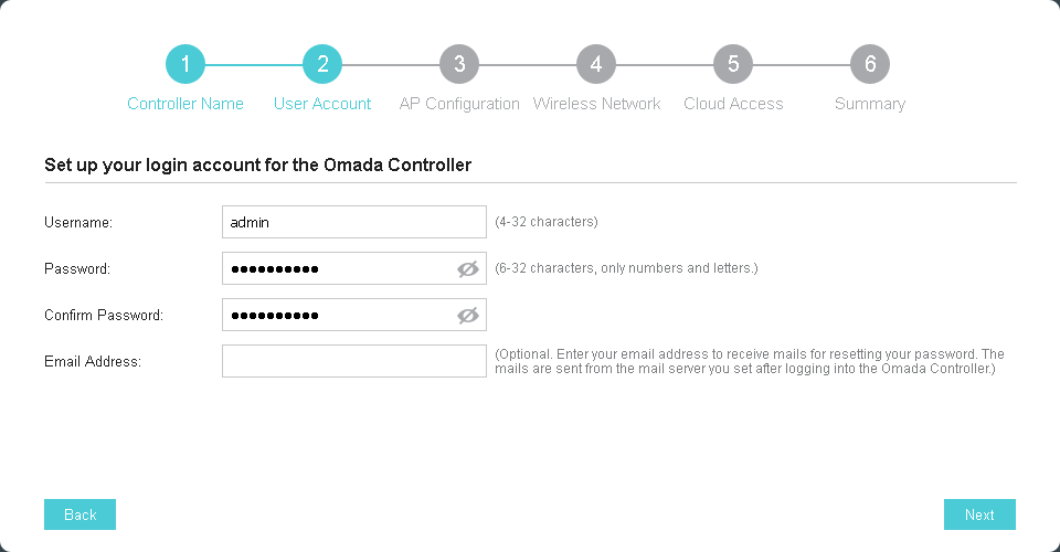
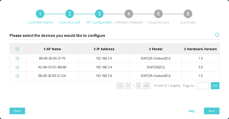
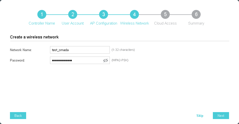
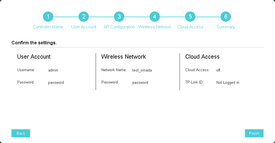
The first time you connect to the controller, the initial setup wizard automatically starts, with which you can fully prepare the wireless network for work in six simple steps. Since the OC200 controller is not interesting for administrators by itself, but in conjunction with the access points it supports, it is also necessary to connect access points to an existing wired network. Access points can be placed with the controller on the same IP network or in different ones, we wrote more about this in the section devoted to the consideration of possible topologies. Of course, access points can be added later - after the initial configuration of the controller is completed.
Speaking of access points. Currently, ten of our latest indoor and outdoor models are supported: EAP330, EAP320, EAP245 (October new), EAP225, EAP225-Outdoor, EAP115, EAP110, EAP110-Outdoor, EAP115-Wall, EAP225- Wall
The controller automatically detects access points located in it on the same IP subnet. The administrator only needs to specify which devices need to be added to the network.
If the controller and access points are located in different IP subnets, then you can use one of the following methods to connect the points to the controller.
Method number 1
Connect to a subnet with access points of a computer or laptop with the pre-installed Omada Discovery utility. This utility allows you to detect wireless devices in the local segment and add them to the OC200 controller.
Unfortunately, this approach cannot be called scalable, since the administrator will need to connect to all segments where access points can be located.
Method number 2
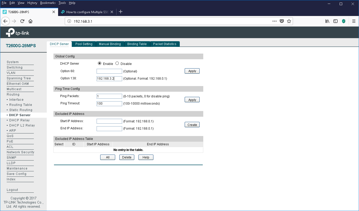
Using option # 138 of the DHCP protocol. This option allows you to inform the access points of the IP address of the TP-Link OC200 wireless controller. Having received information about the location of the controller, the access points will begin the process of connecting to the latter, the administrator will only have to allow the connection of access points to the network.
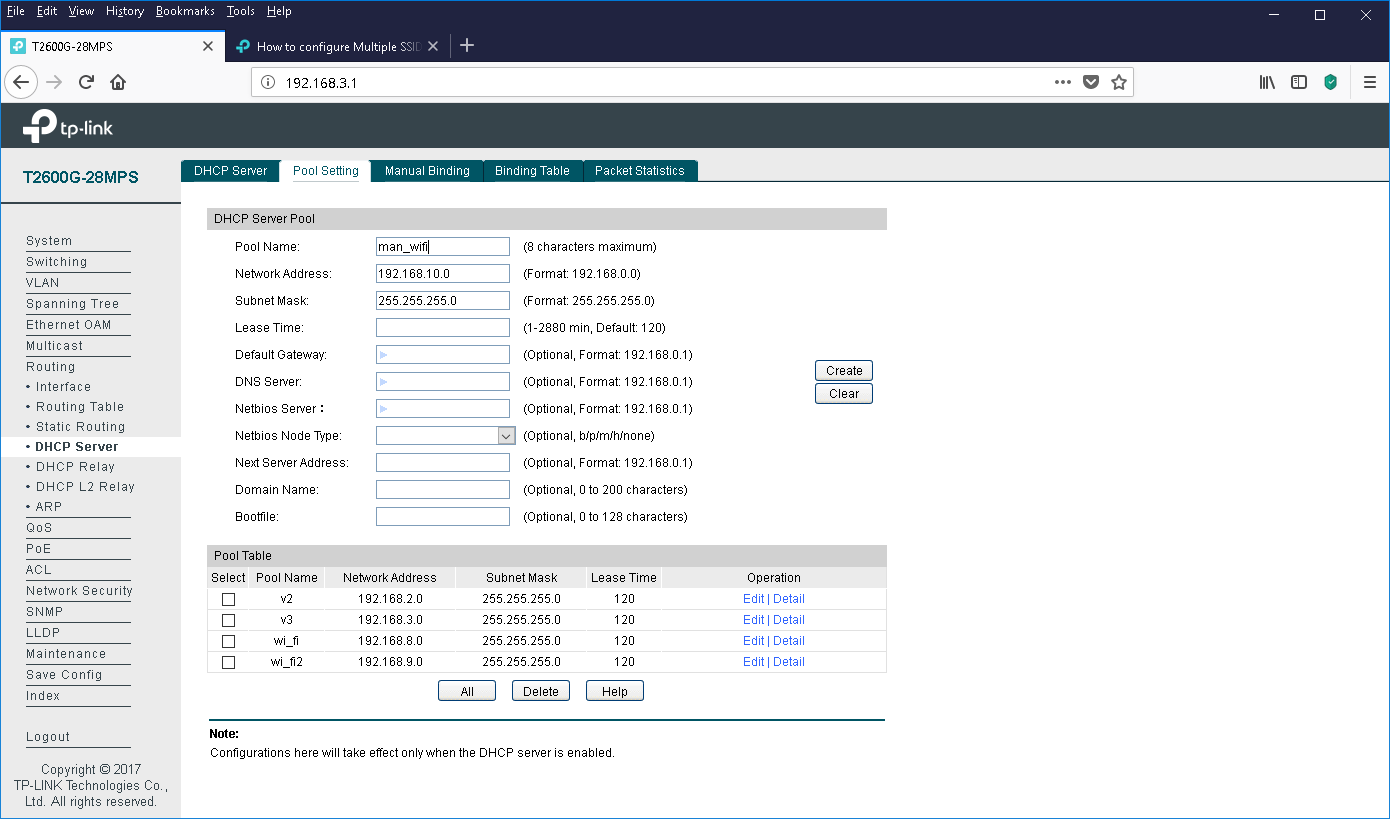
We will describe the entire procedure for configuring the core network for connecting access points in more detail. The first thing to start is to create virtual networks on the switches. As an example, we will consider the TP-Link T2600G-28MPS switch. Virtual networks 8 and 9 will be used to bind to the SSID, while we created VLAN10 to manage access points.
The second step is to configure the interfaces to which the access points are connected, transferring them to trunk mode. We will leave the controlling virtual network on these interfaces without a tag.
It is time to create L3 interfaces for the corresponding virtual networks.
For each virtual network in which wireless users can be located, as well as for the control network, you need to create the appropriate DHCP pools.
The final step is to specify the IP address of the OC200 wireless controller in option field 138. You
can verify the correctness of the settings by requesting registration points from the access points to the controller.
The initial configuration of the core network, controller and access points is completed. The only thing I would like to note is that the OC200 wireless network controller supports access points located on several sites (sites). In the case of using OC200 to build such a distributed wireless network, it will also be necessary to take care of the connectivity between the sites. Two methods for connecting remote access points to the controller are supported here.
The first, most obvious, is the organization of a site-to-site VPN connection between sites. With this connection, the controller and access points have the simplest configuration, since full IP connectivity between the networks of the head office and branches is ensured.
The second, slightly less obvious way is to use the virtual server function on the head office border router. This router performs port forwarding (PAT) inside the network, providing external access to the internal resources of the local network. In this case, in the branch networks, DHCP servers must be configured so that the value of option No. 138 is equal to the IP address of the WAN interface of the head office border router.
However, it seems to us that in most cases a tunnel connection between the head office and branches will nevertheless be realized, so the second method is extremely rare, although quite possible.
Firmware update
When performing maintenance on the wireless infrastructure, it is necessary to update the firmware for the equipment used on a regular basis. Updating should be done both for the controller itself and for the access points it controls. We will leave behind the scenes issues of updating the firmware of devices in a wired core network.
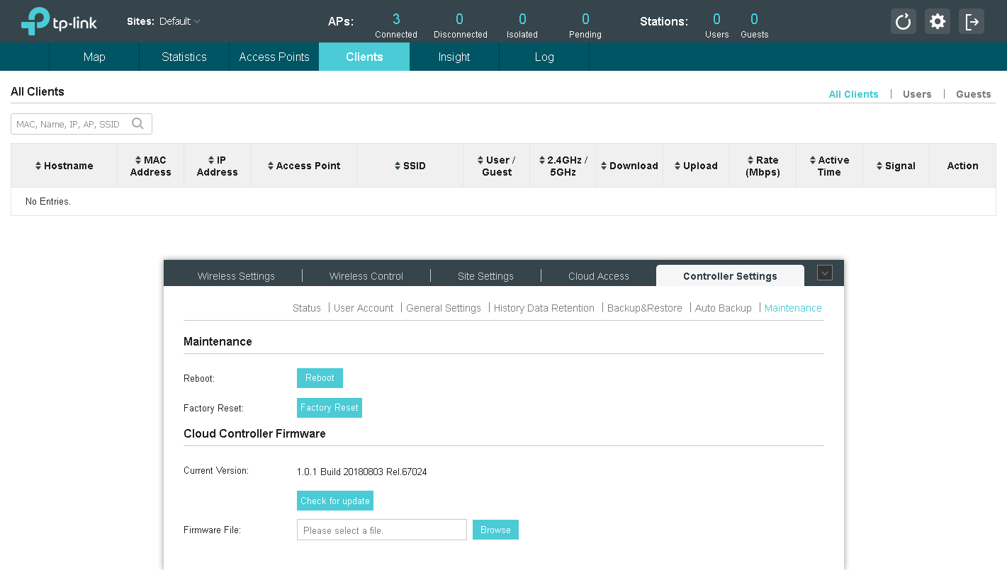
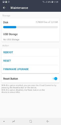
Controller firmware is changed using the Maintenance menu item on the Controller Settings tab. Updating can be done in manual or semi-automatic modes (in the latter case, the controller must be connected to the global network). When updating the controller manually, you only need to download the previously downloaded file with the new firmware onto it. The whole procedure takes several minutes and does not require any specialized knowledge from the administrator.
You also need to update the firmware of the access points. Since all access points are controlled from the controller, you must use the controller to update their firmware (Batch Upgrade menu of the Site Settings tab).
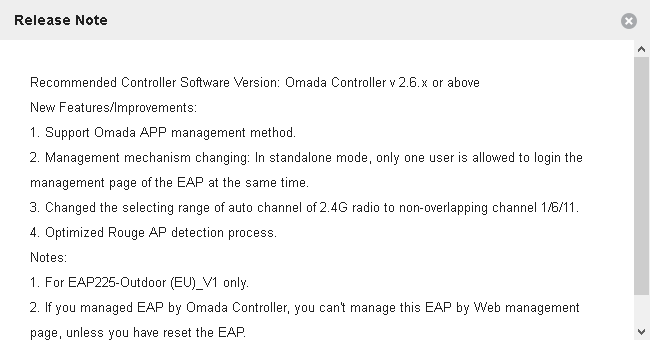
Access points of the same type are updated at the same time. This can also be done in manual or semi-automatic modes. When updating automatically, the controller will download the necessary file from our website and update it. The administrator will only have to wait for the completion of the process.
We usually post new firmware on automatic update servers with a slight delay; up to this point they are available only for manual download and update. Changing the firmware version in manual mode is a little more complicated than in semi-automatic mode: you just need to download the image from our website and upload it to the controller.
Even if your wireless network is working flawlessly at the moment, we still recommend periodically updating it, since the latest firmware versions may contain new functions or optimizations of existing ones, include support for new devices and technologies, and provide enhanced security.
Web interface
One of the ways to control the wireless controller is the web interface, which can be connected using any modern browser.
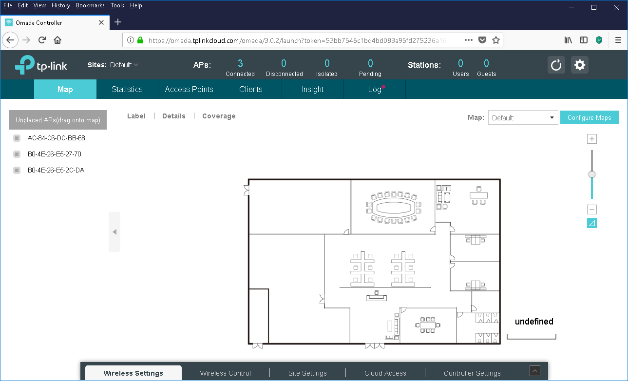
A quick look at the options on the top menu. The Map menu, perhaps, provides the most visual information. With it, the administrator can indicate the location of existing access points on the plan, and the controller will show the estimated coverage area. I would like to emphasize that the intended coverage area is displayed, since in reality it is necessary to take into account many additional factors, such as materials of obstacles along the path of radio waves, the presence of interference sources, location of subscribers, and so on. When developing complex and responsible projects, a complete radio intelligence is indispensable.
The TP-Link OC200 controller can be used to control the operation of access points in very large networks (up to 100 access points are supported (up to 50 recommended), geographically dispersed. The Omada Controller software solution, using the recommended platform configuration, supports up to 500 access points. For the convenience of administering distributed sites, the use of "sites" is recommended, which allows you to group devices by geographical feature.
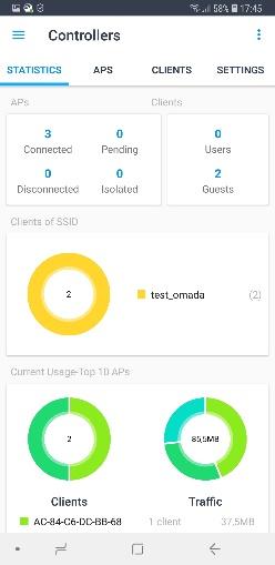
Statistical information about managed access points, the number of connected wireless clients, consumed traffic, and so on can be obtained using the Statistics menu.
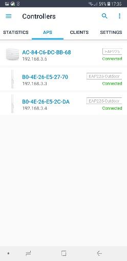
You can get more detailed information about a specific access point, as well as make its individual settings using the Access Points menu. So, for example, you can change the settings of the radio module, enable or disable the redistribution (balancing) of clients between access points and detection of unmanaged points, change the parameters supported by the point of wireless networks.
A list of connected wireless clients is available in the Clients menu.
The Insight menu is also designed to display statistics, but only this time the statistics are displayed for wireless clients and all "foreign" access points that do not belong to our controller.
If you need access to the log information, refer to the Log menu.
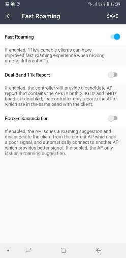
All global settings are made using the lower menu items. So, for example, the Wireless Settings item contains basic and advanced parameters of wireless networks, roaming control options, and mesh-network settings. It should be noted support for IEEE 802.11k / v standards for fast roaming. Support for IEEE 802.11r is on the way.
Mesh technologies make it possible to slightly change the standard approaches to building wireless networks. Now you can combine a wireless access point to a core network into a wireless segment. You can learn more about our implementation of mesh networks using the special page (https://www.tp-link.com/en/faq-2283.html) containing answers to frequently asked questions.
Wireless network access settings are controlled using the Wireless Control menu. Using this item, the administrator can create access lists that regulate traffic flows between specific subnets; perform filtering based on the MAC addresses of client devices, force users to undergo additional authentication on the captive portal, and configure quality of service settings.
A couple of additional words need to be said about our captive portal. With its help, clients are authenticated using a password or a local user database, a remote RADIUS server or portal server, via SMS or using a Facebook account, voucher, or even without any additional authentication.
You can enable or disable the lights on devices using the Site Settings menu. Here you can also change the access settings for access points, set the reboot schedule, manage the settings for sending log information to remote servers, manage firmware, enable and disable access to the command line, change the virtual network number for management.
To control the OC200 controller itself, refer to the Controller Settings menu.
These are, perhaps, all the main points regarding the work with the web interface of the controller.
Mobile app
It is also worth saying a few words about the TP-Link Omada mobile application, which is ideal for remotely managing a company's wireless network. The administrator no longer needs to constantly carry a laptop with him, since all the necessary functions are also in the application developed for smartphones based on iOS and Android.
In addition, TP-Link Omada allows you to manage a wireless network not only with a local connection to the company’s network, but also using a cloud service, which is worth a closer look.
White Manes: Cloud Service
OC200 supports working with our cloud service, connecting to which will allow the administrator to perform remote configuration of equipment.
There are other remote control methods. So, for example, you can configure “port forwarding” on the company's border router so that incoming connections to a specific port are automatically broadcast inside the network to the controller address. Is this approach safe? Definitely not. Of course, you can configure additional rules on the corporate firewall that restrict the list of IP addresses from which you can connect, but we do not consider this the best solution.
Another way to remotely control your wireless network (more secure) is to use a VPN connection to your corporate network. When connecting using a VPN (for example, IPSec, OpenVPN, SSL, or even PPTP with MPPE), the administrator establishes a secure connection over which control traffic will be transmitted.
However, a simpler way to securely manage is to remotely connect using our cloud service. Consider the procedure for connecting the controller to the cloud.
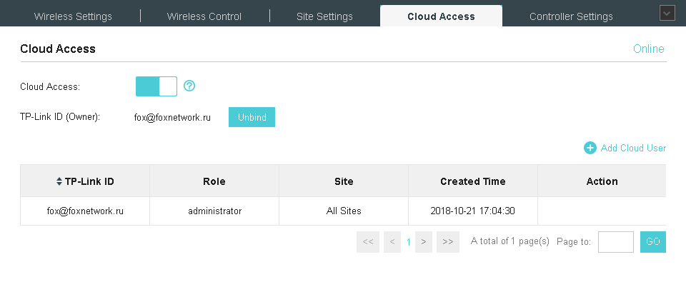
There are two ways to connect. The first is to specify the cloud user credentials directly on the controller (Cloud Access tab).
If you do not have the required account yet, you can create one in a couple of minutes.
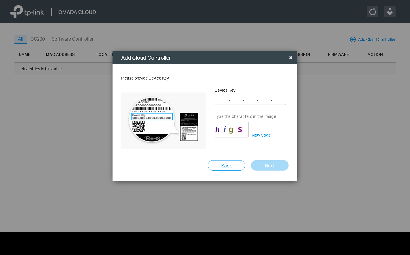
The second way is to add the controller directly from the cloud user’s personal account - you only need to specify the device key (of course, support for access from the cloud must be activated on the Cloud Access tab). The device key is located on a sticker on the bottom of the controller housing.
Regardless of the selected method of connecting the OC200 controller to the cloud service, information about the device will be available in the administrator’s personal account on our website.
Now, to remotely control a wireless network, you just need to connect to our site using a mobile application or any modern browser, enter your personal account, and you can start managing it.
You can connect several controllers to the account of one cloud user, which will allow you to manage wireless networks of different departments or different companies from a single place.
It is also worth noting that there is the possibility of remote control of the controller by several users with different access rights, you only need to add them to the device indicating the role of each account.
Remote control of the controller using a cloud service is possible not only using a web browser, but also using the TP-Link Omada mobile application.
The association of the new OC200 wireless controller with a cloud user using a mobile application is even faster and easier: just scan the QR code located on the sticker on the controller’s case.
Conclusion
So, here's the bottom line:
- Centralized wireless network management: 100 access points (up to 50 recommended), support for remote sites, performing one-click maintenance operations, a cloud service and a mobile application, and automatic backups.
- Advanced functions of the wireless network: MU-MIMO, switching between frequency ranges, beamforming, load balancing and the possibility of limiting the available bandwidth, wireless speeds up to 1900 Mbit / s, mesh networks, roaming, software relevance checking and automatic updating.
- Options for ensuring stability and security: captive portal, access lists, support for multiple SSIDs and VLANs, additional authentication, scheduled actions, support for various topologies.
- Hardware platform: a productive chipset, professional antennas, PoE support, floor / table / wall / external placement of access points, various modes of operation of devices and an acceptable price slightly lower than analogues (~ 7 thousand rubles).