DST40 transponder: principle of operation, history of emergence and hacking, as well as a bit of brute force practice
 Once upon a time, back in the nineties of the last century, the growing automotive market was in dire need of serious anti-theft systems (hereinafter referred to as immobilizers). For car thieves in those days there were no special obstacles that prevented the engine from starting with a mechanical copy of the key, or even without a key at all - by simply closing the wires. Immobilizers were needed that could significantly complicate the process of starting the engine and further car theft without a native ignition key.
It was then that the idea of creating a compact radio module (hereinafter referred to as the transponder) came into light, which was built directly into the car’s ignition key. In the car, an immobilizer was installed, communicating with the transponder via a radio channel. The immobilizer sent a request to the transponder, and the transponder answered with a certain code, without which the immobilizer did not allow the engine to start. However, at first transponders were still pretty primitive, relatively easy to clone devices. It was enough to have a radio interceptor and a light head on the shoulders to understand the exchange algorithm and simulate the response of the transponder. A radical change in the algorithm of communication between the immobilizer and the transponder was required.
Today I will tell you about the history of the emergence and subsequent hacking of one of these algorithms, as well as the practical details of the brute force process of the secret encryption key.
Further on, all pictures will be clickable so that they can be examined in detail if desired.
Part One: Native American Joe
So, demand creates supply: gradually, systems using encryption in the process of transmitting data over the air began to appear on the market. These systems, in fact, performed the process of wirelessly identifying the owner of the key. At the same time, the secret key stored in the transponder was not broadcast in any form, but was used for cryptographic “signing” of the request received from the immobilizer. One of these systems was developed by Texas Instruments engineers. The transponder they developed was called Digital Signature Transponder (abbreviated as DST).
 The DST transponder turned out to be very small-sized, which made it possible to integrate it into various compact tokens without any problems: for example, in car ignition keys or in key chains. In the above photo, in the handle near the blade, you can see the hole closed by the plug through which the transponder is placed inside the key. And the use of a hash scheme in its design made the radio sniffing process completely useless (for the time being, for a while - but more on that later), because so different data blocks were transmitted through the air that it became logically impossible to trace at least some kind of dependence in them .
 The transponder consists of the following main components:
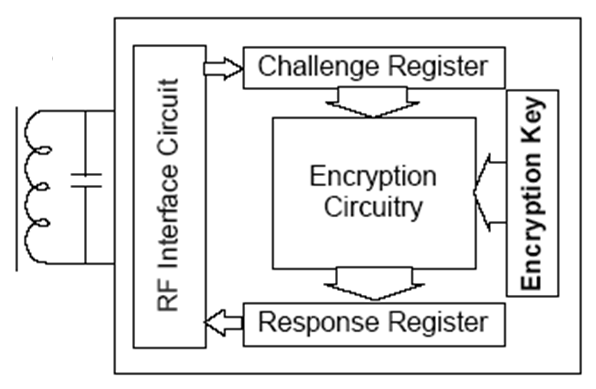
- Antenna and transceiver (hereinafter referred to as the transceiver): designed to power the transponder and to communicate with the base station via radio channel.
- Encryption scheme: designed to hash the request received from the base station.
- Non-volatile rewritable memory: designed to store the encryption key and some additional parameters (for example, transponder serial number and manufacturer ID).
The transponder is also programmed over the air - without a direct connection to the programmer. You can overwrite almost any information, but only if the write protection bits are not cocked. The recorded transponder can easily be linked to the base station without the help of any additional devices (a prerequisite is the coincidence of the manufacturer ID in the transponder and in the base station).
The algorithm of the entire wireless authentication system is as follows:

- The base station transmits an unmodulated radio signal of such power and duration that it is enough to power the entire electronic circuit of the transponder located in the coverage area of the base station transceiver.
- The base station, using a random number generator, generates a 40-bit request, stores it and broadcasts it using amplitude modulation of the radio signal.
- The transceiver emits an unmodulated radio signal for some time - so that the transponder has enough power to perform computational operations.
- Having received a request from the base station, the transponder performs its hashing using the DST40 algorithm using a 40-bit encryption key stored in its non-volatile memory: the result is the so-called “signature”.
- The transponder transmits a digital signature and service information to the base station.
- The base station hashes the request just sent to the transponder using the same encryption key that is stored in it: if the result matches the result received from the transponder, then authentication is considered successful. If this base station is used as an immobilizer of a car, then after successful authentication, it sends permission to start the engine to the central computer of the car.
It is not clear what the considerations of the development engineers were based on, but the fact remains: the length of the encryption key used in the hashing process is only 40 bits (this, by the way, is why the algorithm was called DST40). Such a length of the encryption key, from the modern point of view, is completely insufficient to ensure at least some decent security. But at that time, apparently, the development engineers did not think so. In addition, the DST40 algorithm is purely proprietary and is disclosed to manufacturers only under the strictest non-disclosure subscriptions.
In the future, manufacturers' confidence in the safety of the transponder continued to grow stronger, since for a long time the algorithm remained unbroken.
As a result, the DST40 transponders have become extremely popular. They were adopted by a number of large automotive corporations (for example, Toyota, Ford, Lincoln, Nissan and others). Many millions of cars whose immobilizers use DST40 transponders gradually flooded not only the US markets, but also the markets of other countries actively importing cars from the USA. Moreover, these transponders also began to be used in the SpeedPass contactless payment system , which is rapidly gaining various fast foods, supermarkets, restaurants and gas stations in the USA.
Part Two: And thunder struck!
Everyone has long known that the Indian Joe remains elusive only until the moment when no one needs him. So in this story, the DST40 algorithm remained unbroken only until young, energetic guys took up it.
 It happened in 2004. By that time, the confidence of Texas Instruments engineers in the robustness of the DST40 algorithm had become so great that they were simply bursting with pride and the desire to at least share their achievements with anyone. And they decided to send one of the employees of the German division of the company - Dr. Ulrich Kaiser - to the fourth AES conference with a small overview report on the DST40. This report was the beginning of the end of the Indian Joe.
The fact is that this conference was attended by a cryptography expert, a professor at Johns Hopkins University of Information Security (USA), Professor Aviel D. Rubin . One glance at the general scheme of the algorithm was enough for him to see serious security holes in it. This is what this diagram looked like:
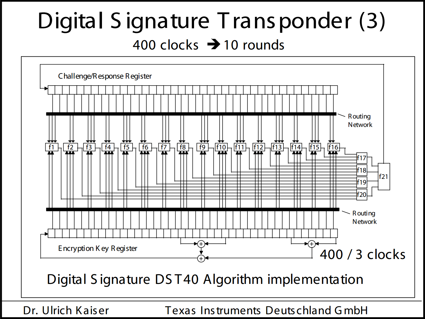
Despite the fact that the scheme was very general and lacked many subtle details, the trained eye of an experienced cryptographer immediately caught on to several vulnerabilities: firstly, it was clear that the encryption key and request / response registers underwent minimal modifications for each clock cycle - in just one bit. Secondly, it was obvious that there was a “weak” encryption key consisting of only zeros - during the hashing process, it would remain zeroed to the very end. This opened up the possibility of conducting various cryptanalytic experiments on the transponder that could reveal its internal structure. And thirdly, the key length was only 40 bits, which by the standards of 2004 was completely insufficient to withstand the brute force performed using hardware.
 Of course, Evie understood that a large company, which occupies a significant segment in the production of such devices, cannot be convinced of the weakness and vulnerability of the algorithm simply by words. Then he came up with the idea of hacking the DST40 into practice - which would be the most compelling argument. First of all, he decided to assemble a team of several university students. He chose the most energetic and capable guys, whom he proposed to do this business: to dig into the algorithm, and at the same time to tighten the theoretical knowledge and practical skills in cryptography and cryptanalysis. So the team was born, which included (in the above photo, from left to right) Adam Stubblefield , Aviel D. Rubin , Stephen C. Bono and Matthew Green (Matthew Green ).
 The next step was the acquisition of the TI Series 2000 Developer Kit - LF RFID from Texas Instruments. This set included a transceiver for communicating with transponders and several transponders, which, however, were completely useless, since they did not perform encryption using the DST40 algorithm. So the guys needed to get the transponders separately.
Among other things, by the way, this developer kit also included software that allowed encryption using the DST40 algorithm. However, the guys, as they later vowed to assure everyone present at the USENIX symposium, did not disassemble and debug the program code to get to the soft pink body of the proprietary algorithm, as this was prohibited by the license agreement.
Instead, they decided to use the "predictor" or "black box" method for hacking. In simple terms, they began to conduct various experiments, writing different encryption keys to transponders, as well as transmitting different requests to them and studying the hash results obtained from them.
It was seen from the Kaiser scheme that the basis of the encryption scheme is the Feistel network widely used in other encryption algorithms on logical elements with fixed truth tables. To completely crack the algorithm, the guys needed to solve three problems:
- Check if the Kaiser scheme is true.
- Determine the wiring of signals from each of the bits of the key registers and the request to the logical elements.
- Compute the truth tables of all logical elements.
I will not go into details of the experiments that are being conducted: anyone who is interested can see them for themselves in this document , presented to the public at the 14th USENIX Security Symposium in Baltimore in 2005.
I can only say that as a result, the guys managed to successfully solve all three problems and restore the complete connection diagram of the functional blocks included in the DST40 encryption module, including the truth tables of these blocks. Moreover, it should be noted that the real functional scheme turned out to be not fully consistent with the Kaiser scheme. There were several differences:
- After the hash starts, not 400, but 200 clock pulses are fed to the scheme.
- The request register for each measure is shifted not by one, but by two bits at once.
- The logic element indicated on the Kaiser scheme “F21” has not one, but two outputs, which, before getting into the leftmost (according to the scheme) two bits of the request register, are XOR with the two rightmost bits from the same register.
- To calculate the next left (according to the scheme) bits of the encryption key, the wrong bits are used that are shown in the scheme.
The guys also managed to find out the algorithm for modifying the encryption key: the key is changed for every third measure, starting from the second.
Not only that, it turned out that the resulting hash is not transmitted by the transponder to the ether - not all 40 bits, but only 24 of them. The consequence of this is the appearance of a large number of false results during further enumeration of all possible combinations of encryption keys. However, this did not become too big a problem - it was enough to check the next key found again, but with a different request / response pair. If the second check also gave a match, then the key was considered found.
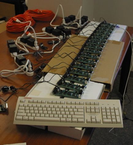 Further, the guys developed a hardware key brute forcer based on the board with the FPGA XILINX on board, which cost them a little less than $ 200. On the chip of this FPGA they managed to place 32 hashing cores synchronously operating at a frequency of 100 MHz. Each of the cores sorted out its sub-range of encryption keys. Ideally, one such board should sort out the entire range of keys in about 19 hours of operation:
 The first experimental rabbit was the ignition key from a 2005 Ford Escape SUV car equipped with just such a transponder. Using the developer's kit, two random requests were transmitted to the key and two corresponding responses were received. These two pairs of requests / responses became the source data submitted to the brute force forcing before starting the search. Less than an hour after the start of the search, the secret key was successfully found.
 The next step was the manufacture of a simulator of this transponder, with which you could start this car. A compact personal computer was taken as the basis, with a transceiver board installed in it and an external antenna connected to this board. To ensure autonomous power supply of all iron, UPS was used with an additional battery unit connected to it. A program was launched on the computer, which listened through the transceiver while waiting for a request from the immobilizer. Upon receiving such a request, the program hashed it and transmitted the result back to the air. To start the car engine, a mechanical copy of the ignition key, which does not contain a transponder, was used.
In the video below, Adam and Matthew demonstrate the process of starting the engine using a simulator:
Then, using this simulator, they successfully purchased gas at a gas station with the SpeedPass payment system:
After the successful completion of all these experiments, it was decided to publish the information received. At that time, Evie was a member of the board of directors of the USENIX association - therefore, the publication of this information at the next USENIX security symposium became a logical decision.
However, in order to prevent the rapid collapse of payment systems and not to give thieves a tool for easily breaking into immobilizers, the guys did not publish all the information. For example, the final hash function diagram has not been published. The only thing they provided as confirmation of the veracity of their words is formulas that describe the key hashing algorithm and the truth tables of the functional elements that make up the Feistel network. This was completely enough for Texas Instruments engineers to realize the complete fiasco of the DST40 algorithm.
Part Three: But Can We Benefit From It?
It was 2009. A wave of crisis, which was gaining strength, was rolling along the earth with a roar. Two people, let's call them, relatively, Steve and John, were actively looking for options for earning extra income. The sensational story about hacking DST40 transponders prompted them to think that you can make a little money on this. The idea was to offer the installation of remote engine start systems to car owners equipped with similar immobilizers. At that time, similar systems already existed, but all of them required the sacrifice of one car key: it had to be placed in the cabin in the immediate vicinity of the remote start device. It is clear that this deprived the use of the immobilizer of any meaning whatsoever and forced the car owner to install a separate alarm in the car.
Steve and John got down to business, studied the document published at the USENIX symposium and figured out the hash mechanism. As a result of their labors, such a scheme came into being that fully complies with the formulas published on page 14 of the above document:
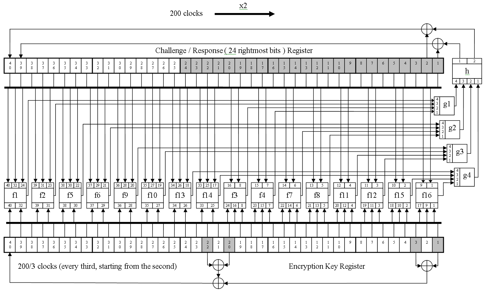
Then they made two designs: the
first of them was a DST40 transponder programmer. It allowed reading open information from transponders, transmitting a request to a transponder and receiving a hash result from it - just like a car immobilizer does, and also allowed writing open information to a transponder along with an encryption key. Using the programmer, two request / response pairs were received for the ignition key from the 2005 Toyota Camry.
The second design was a brute force engine built on the basis of the Xilinx Spartan 3E FPGA chip. The brute-forcer enabled the brute force method to find the encryption key stored in the transponder. To do this, the input of the brute force was supplied with the initial data in the form of two combinations of requests / responses and the encryption key, from which it was necessary to start the search. The bruteforce worked at a frequency of 135 megahertz, contained 32 hashing cores on an FPGA chip, and performed a complete enumeration of all combinations in about 14 hours.
The result was, frankly, not encouraging: to wait a few hours when the brute force worker did his job was not a very pleasant experience. Therefore, Steve and John turned their eyes to another area of data transfer - between the central computer of Toyota and the immobilizer unit. After conducting a small examination and several tests, it turned out that this site, although it has some masking of the transmitted data, is so primitive that it was not difficult to figure it out and introduce its device into the gap of this tract. While the device was working in standby mode, it simply transmitted data from the computer to the immobilizer and back through itself. If it received a command at a remote engine plant, it disconnected the immobilizer and began to communicate with the computer on its own - simulating positive responses from the immobilizer. And the most important thing in this whole process was that the response of the immobilizer depended only and only on the request of the computer. The ignition key was simply not needed.
The programmer and brute force forwarder remained unclaimed.
Part Four: Purely Sporting Interest
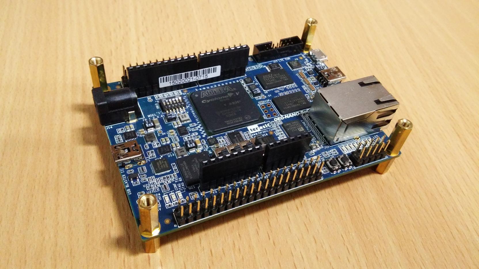 A few more years passed after the events described above, and then one day the DE0-Nano-SoC board fell into my hands . Her heart is the Altera Cyclone V SE 5CSEMA4U23C6N chip. It contains a dual-core HPS-processor (Hard Processor System) ARM Cortex-A9 and FPGA with 15094 adaptive logic modules (ALM). Included with the board, the manufacturer provides Linux, which is deployed to a microSD memory card. This makes it easy to implement the user interface - without spending a lot of time on it. After mastering this device, I recalled the story of hacking the DST40 transponder and there was a purely sports interest - how many hashes can be squeezed per second with the DST40 keys brute force using such a device?
Having on hand the scheme drawn by Steve and John, as well as two pairs of requests / responses received by them from the Toyota key, I got down to business. At first, a simple way was chosen to extensively increase the number of hashing cores, of which as many as 128 pieces fit on the FPGA crystal of this board:
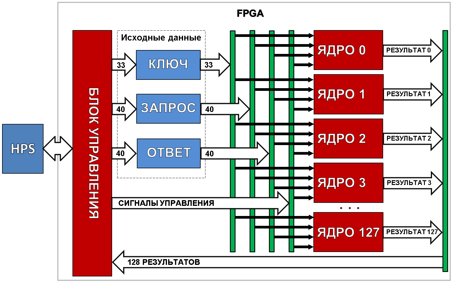
The following components are displayed in this diagram:
- HPS processor - runs the dst40 program. It requests the initial data from the user, loads them into the registers of the control unit, starts / stops the search process and displays information about the current state on the screen.
- Control block. Its task is to prepare the source data for all hashing kernels, manage their work, verify the results and transfer them to the HPS.
- Hashing kernels. Each core generates an initial key of two parts: a 7-bit fixed high part that matches the serial number of the core (00H for core number 0, 7FH for core number 127) and a 33-bit low-order variable obtained from the control unit. The kernels perform the hashing of the request using the DST40 algorithm; at the end of this process, the hash result is compared with the response and the comparison result is transmitted to the control unit.
An approximate algorithm for the operation of the entire device is as follows:
- The program asks the user for initial data: two requests sent to the transponder and two corresponding responses received from the transponder, as well as an encryption key from which to start the search.
- The program loads the first request / response and key into the control unit and starts the search process. After that, it waits for the control unit to inform it of the detection of a match or the exhaustion of the keys being searched.
- The control unit sets the request / response and the key to the inputs of the source data of all the cores and gives them the command to start hashing.
- Each core hashes a request. This will take 200 clock cycles. At the end of work, each core compares the hash result with the response and sends the comparison result to the control unit.
- The control unit evaluates the results of all the cores: if no matches are found, it increments the key and proceeds to step 3 of the algorithm.
- If at least one core detects a match, the control unit passes the key found to the program along with the kernel number that detected the match.
- The program transmits the second request / response pair to the control unit and instructs it to continue searching from the current key.
- The control unit performs steps 3 through 5 of the algorithm. If a match is again found, information about this is transmitted to the program.
- The program compares the key and the kernel number with the previous ones - if they match, then the key is found. The search process is complete. If they do not match, then the search continues.
The hardware of the design has earned at a clock frequency of 200 megahertz. As a result, search speed was 128x200x10 6 /200 = 128 million hashes per second. The device performed a complete enumeration of all options in 2 hours 24 minutes. This, of course, was a very good result, but still not so good - to stop there.
Next, I will describe several steps taken to speed up the search process. So…
Step one
Let's start by optimizing the algorithm. Take another look at the hash scheme above. We see that the hash result is read from the lower 24 bits of the request / response register. The high 16 bits are not used. A logical question arises: why perform the last 8 measures if their result is then thrown out? Answer: there is absolutely no need. It is enough to apply 192 clock cycles to the circuit, and then take the hash result from the high 24 bits of the register. So let's do it: it will give us a completely free four-percent increase in speed.
Second step
Let's look at the truth tables of the logical elements at the very end of the document.
Take a close look at the truth table of the function Fe
00000: 0

00001: 0

00010: 1

00011: 1

00100: 0

00101: 0

00110: 1

00111: 1

01000: 0

01001: 0

01010: 0

01011: 0

01100: 1

01101: 1

01110: 1

01111: 1

10000: 1

10001: 1

10010: 1

10011: 1

10100: 0

10101: 0

10110: 0

10111: 0

11000: 1

11001: 1

11010: 0

11011: 0

11100: 1

11101: 1

11110: 0

11111: 0
It is easy to see that the lines are duplicated in pairs. This means that the lowest input bit does not affect the result and can be discarded without any damage. No sooner said than done.
Now the truth table has acquired this form
0000: 0

0001: 1

0010: 0

0011: 1

0100: 0

0101: 0

0110: 1

0111: 1

1000: 1

1001: 1

1010: 0

1011: 0

1100: 1

1101: 0

1110: 1

1111: 0
This does not give an obvious increase in speed. However, as you know, any reduction in the number of combinatorial logic in synchronous circuits has a positive effect on the possibility of increasing the clock frequency.
As a result, such a kernel scheme was born that took into account the changes described above (also in it the bits in the registers are renumbered so that the count goes from scratch - this is more common):

Third step
Programmers trying to get the maximum speed out of a looped piece of the program have such an optimization method as “loop unrolling”. It consists in the fact that the loop counter decreases N times, and the sequence of commands executed in this cycle is repeated one after another N times. This reduces the redundancy introduced by the cycle counter maintenance teams.
Let’s try and we will use this method: we will expand the entire 192-cycle cycle into one solid line. The implementation of this option is quite possible, since the work of each cycle depends only on the results of the previous cycle and nothing else:
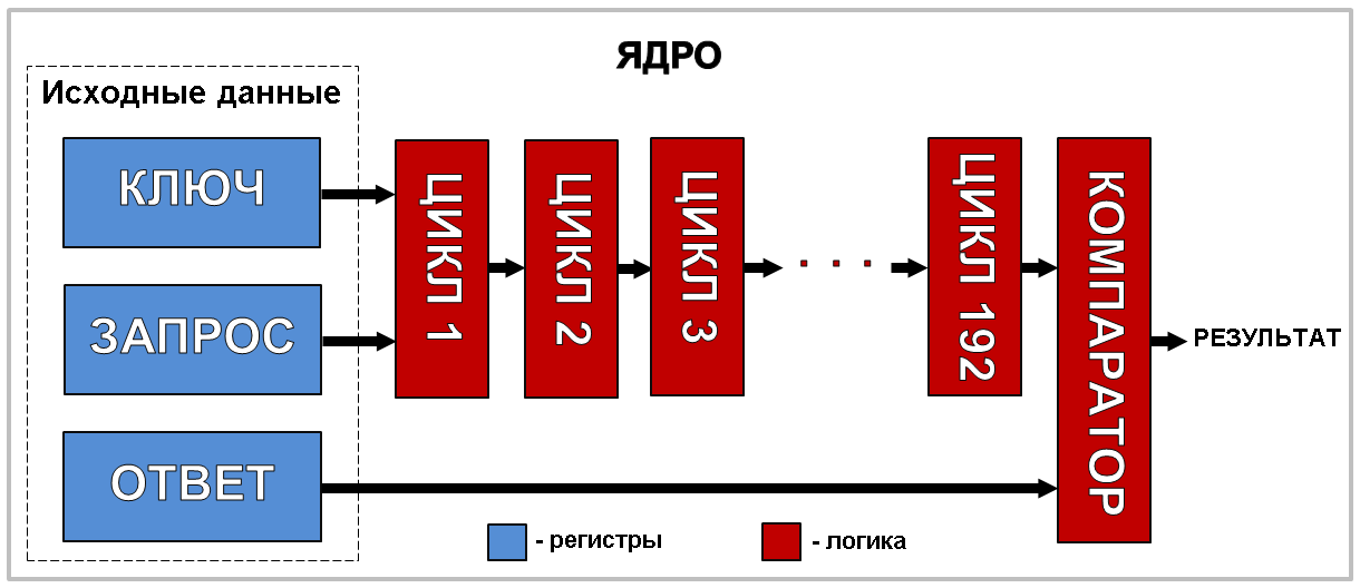
In this scheme, each logic block with the name “CYCLE N” includes the entire Feistel network used in the DST40 algorithm. It is clear that the length of the logical circuits will become abnormally large and the clock speed will have to be significantly reduced. However, such a scheme will produce a result for each measure, and not for each 192nd measure, as it was originally - worth a try!
We implement such a scheme and test it: as expected, the clock frequency had to be reduced to 2 megahertz, and there was so much logic that 8 cores could barely fit on the crystal. 16 million hashes per second - this is completely frivolous!
Throw this idea in a landfill? In no case! There is another trump card that can now be pulled out of the sleeve. It is called a conveyor. I believe many of the readers know about pipelines. And if it’s not known, I recommend reading about them in a wonderful article by Ivan Shevchuk aka ishevchuk - “ A few words about pipelines in FPGA ”.
So, we cut the logical chain into 192 links, at the joints between which we put two 40-bit registers:

We compile. This design worked at the same frequency as the original design of 128 cores - 200 megahertz. But now new source data comes to its input for each measure. The result is also now removed from the outputs of the circuit for each clock cycle (starting from clock cycle 192). The acceleration was 192 times! Cheers cheers! However, not everything is as rosy as we would like. The core scheme is so swollen that only one core fits on the crystal. The resulting enumeration rate was 200 million hashes per second.
Let's not despair - let's look for a compromise. Let's take a close look at the resulting diagram again. It is striking that the entire chain of 192 links as it were consists of 64 identical blocks of 3 links: in the first link of the block, the key register does not change, in the second - it is shifted by 1 bit, and in the third it does not change again. Let's try to change the scheme: remove the registers cutting these blocks into three parts. Thus, the number of chain links will be reduced to 64, and the length of the logical chains of each link will triple. This will result in a need to lower the clock frequency, but at the same time, the size of the core will have to be significantly reduced.
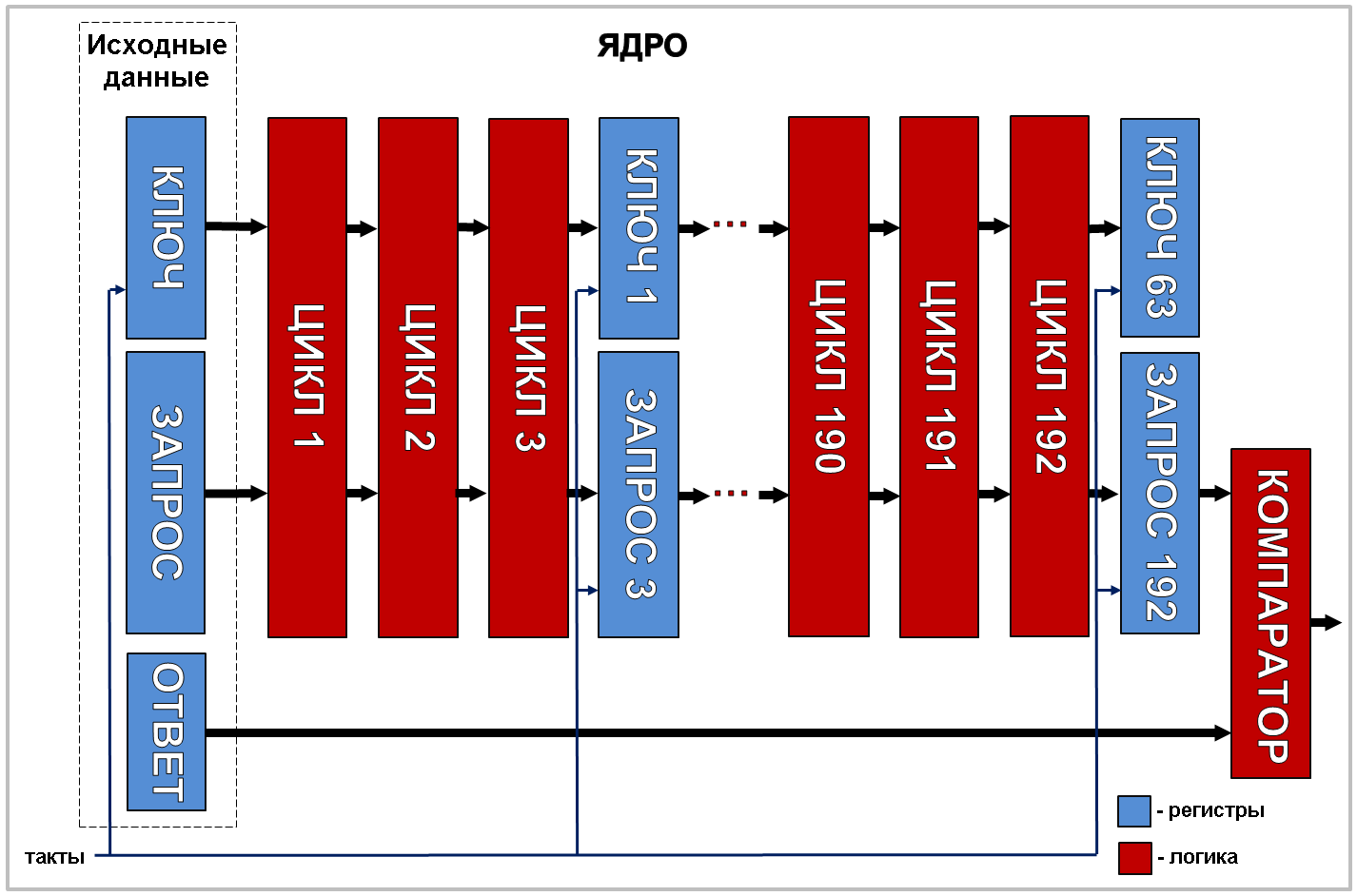
We implement such a scheme and as a result we get the opportunity to place four such nuclei on the crystal. The TimeQuest analyzer allowed to run this circuit at 125 megahertz. But since there were four cores and the scheme gives four results per cycle (starting from the 64th), the total enumeration speed was 4x125x10 6 = 500 million hashes per second. Already quite good!
Fourth step
Well, the final touch is overclocking! Where would it be without him? The 125 megahertz obtained in the previous step is the frequency at which the TimeQuest analyzer does not swear. But the Cyclone V chips have a pretty decent “safety margin” in speed. We will take advantage of this and will raise the clock frequency of the circuit until it starts to make a mistake - skip past the ears with the correct combinations of the source data. To evaluate the correct operation of the circuit, the program in the HPS processor was replaced with a test one: in each cycle it generated random key / request pairs, calculated the answer, loaded all this stuff into the pipeline, and launched the circuit. If after 64 clock cycles the circuit did not report a successful match detection, the test was considered not passed - the circuit frequency had to be lowered. In this way, the limiting frequency was found at which the circuit remained operable: 170 megahertz. At 175 megahertz, the circuit began to fail. At 170 megahertz, the search speed was 4x170x106 = 680 million hashes per second. The device coped with exhaustive search of all possible options for keys in less than 27 minutes.
Below is a video demonstrating the use of this brute force in practice:
Part Five: The Final
The overall efficiency of the DE0-Nano-SoC-based brute-forcer exceeded the efficiency of the 512-core cluster built by the Evi team by about 90 times (the design turned out to be 30 times cheaper and three times faster) - which is not surprising at the present stage.
If anyone wants to "delve" into the source, then this can be done here . There, in the bin directory, there is a compiled firmware for uploading to FPGA (the clock frequency is limited to 150 MHz - for reliability) and a compiled program for running on HPS under Linux.
Then let me take my leave! All health and good luck! Thanks for attention!