Connecting an iButton Temperature Sensor and Key Reader to Queclink GV300 / GV320 Trackers
Queclink GV200 / GV200G, GV300 / GV320 car trackers have the ability to connect an external temperature sensor and iButton key reader to them. The temperature sensor can be used to monitor the temperature of the transported cargo, and the iButton key reader can send messages to the server and control the status of one of the tracker's digital outputs. This article describes how to connect the sensor and reader to the GV300 / GV320 trackers (the differences in these trackers are only in the number of supported GSM frequencies: 850/900/1800/1900 MHz and 900/1800 MHz, respectively).
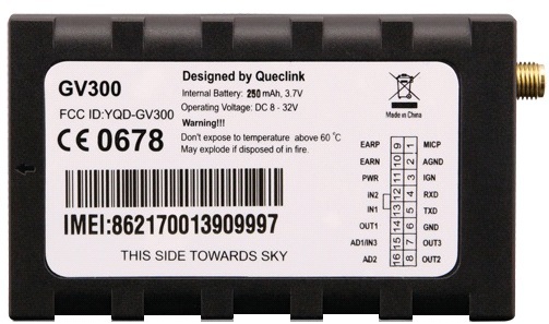
The temperature sensor and iButton reader are connected to the tracker via an additional interface conversion device (1-Wire / RS232-UART) of the AC100 type. The AC100 is part of the 1-Wire Temperature Sensor Kits (kit with temperature sensor) and iButton Kits (kit with iButton key reader). To connect the AC100, the serial port RS232-UART of the GV300 / GV320 trackers is used.
To use the iButton temperature sensor and reader with the GV300 / GV320 tracker, you must:
You can find out the firmware version by connecting the tracker to a computer and running a special program for setting up trackers - the Manage Tool. Select the Help menu, then About. In the window that appears, you can see the line with the firmware version in the tracker, for example this: Device Version: GV320R00A14V08M128_NMX Firmware

versions that support operation with the temperature sensor and iButton reader:
for GV300 - GV300R00A07V15M128_NMX and higher;
for GV320M1281212 and
firmware version GV320X12A12 and later then you need to update it. Instructions for updating the firmware in the tracker are given in the corresponding document (GV300 Track Air Interface Firmware Update V1.00 and GV320 Track Air Interface Firmware Update V1.00).
To work with the temperature sensor and iButton reader, you need to configure the following tracker parameters:
You can configure the tracker using the Manage Tool program or by sending several SMS messages with the appropriate commands to the tracker's SIM card number.
Together with the tracker, you can use one iButton reader and up to two temperature sensors. After connecting new temperature sensors, it is necessary to restart the tracker to correctly determine them.
To configure the serial port of the tracker, use the AT + GTURT command.
It determines what external device the UART port will work with, the exchange rate and the number of data bits, stop bits and the use of the parity bit in the package, and also whether the power saving mode is enabled or disabled and the use of digital input number 1 to enable or disable this mode.
If you enable the power saving mode, the response of the tracker to UART will become slow and to ensure a normal reaction, you must enable the tracker to wake up by affecting digital input 1 (Input ID of Wakeup: Use digital input 1 to wakeup the device).
Configuring UART using the Manage Tool:
- in the command browser (left panel of the Manage Tool) select Other Settings;
- in the command browser select the sub-item Serial Port Setting;
- in the command settings panel, set them as follows:
Working Mode: Used for AC100 devices
Baudrate Index: 115200
Data Bits: 8
Parity Bits: None Parity
Stop Bits: 1
Sleep Enable: Disable the device sleep and the serial port sleep mode
Input ID of Wakeup: Do not use digital input to wakeup the device

Configuring the GV300 UART2 tracker using SMS:
send a message with the following text from your phone to the SIM card number in the tracker: AT + GTURT = gv300,5,12,8, 1,0,2,0 ,,, FFFF $
Configuring the GV320 UART2 tracker using SMS:
send a message with the following text from your phone to the SIM card number in the tracker: AT + GTURT = gv320,5,12,8,1,0,2,0 ,,, FFFF $
The operation mode of the AC100 is set by the AT + GTACD command.
Setting the operating mode of the AC100 converter using the Manage Tool program:
- in the command browser (left panel of the Manage Tool program) select Other Settings;
- in the command browser select the sub-item AC100 Devices Setting;
- in the command settings panel, set them as follows:
I-button timer: 1 seconds
Temperature timer: 10 seconds
Output ID: 3
Out Status: check or uncheck
Duration: 0 x100ms
Toggle Times: 0
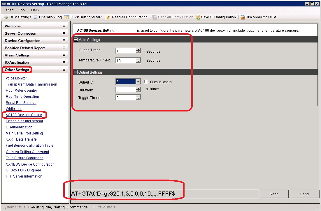
Comments on the parameters of the mode settings command AC100 converter operation:
- I-button timersets the time interval for polling the iButton key reader from 1 to 10 seconds; if set to 0, the reader will not be polled;
- The temperature timer sets the time interval for polling temperature sensors from 10 to 255 seconds; if set to 0, the sensor will not be polled;
- Output ID sets the number of the digital output on which the pulse signal will be generated if a key is attached to the reader. If Output ID = 0, then no digital output will be used to generate a pulse;
- Duration sets the pulse duration from 0 to 255 times 0.1 sec .;
- Toggle Timessets the number of pulses that will be generated at the output from 0 to 255;
- Output Status is used only when Duration = 0 and Toggle Times = 0 and determines the state of the digital output after the key has been touched by the reader. If Output Status 0, then the digital output is turned off, and if Output Status = 1, then the digital output is turned on, and it remains in this state all the time until the power to the tracker is turned off.
Setting the operating mode of the AC100 converter using SMS for the GV300 tracker:
send a message with the following text from your phone to the SIM card number in the tracker: AT + GTACD = gv300,1,3,0,0,0,10 ,,,,, Ffff $
Setting the operation mode of the AC100 converter using SMS for the GV320 tracker:
send a message with the following text from your phone to the SIM card number in the tracker: AT + GTACD = gv320,1,3,0,0,0,10 ,,,,, Ffff $
The iButton key can be used to turn off the ignition in the car. To do this, make the following settings:
AT + GTACD = gv320,1,3,0,0,0,0 ,,,,,, FFFF $
AT + GTOUT = gv320,0 ,,, 0,0,0,1,0 , 0,0,, 0,0 ,,,, FFFF $
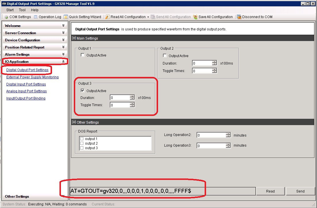
And connect the relay switching the ignition circuit to digital output number 3.After applying power to the tracker, it will turn on digital output 3, this will turn on the relay and power from the battery through the closed contacts of the relay will go to the ignition switch of the car. If you now touch the reader with the iButton key, the tracker will turn off output 3. The relay will also turn off, its contacts will open and the ignition will be de-energized. Further touches with the key to the reader will lead to nothing, the off state will remain until the next shutdown and on or restart of the tracker.
The temperature value is issued by the tracker to the server in the message + RESP: GTERI (extended message about fixing coordinates). To configure the tracker in the mode of issuing such messages, you need to set equal to 1 bit number 1 in the bit mask of the ERI Mask of the AT + GTFRI command.
Setting the mode for issuing extended messages by the tracker using the Manage Tool:
- select the Position Related Report item in the command browser (left panel of the Manage Tool program),
- select the Fixed Report Information sub-item in the command browser,
- check the ERI Mask in the command settings panel checkmark option:
Report AC100 content
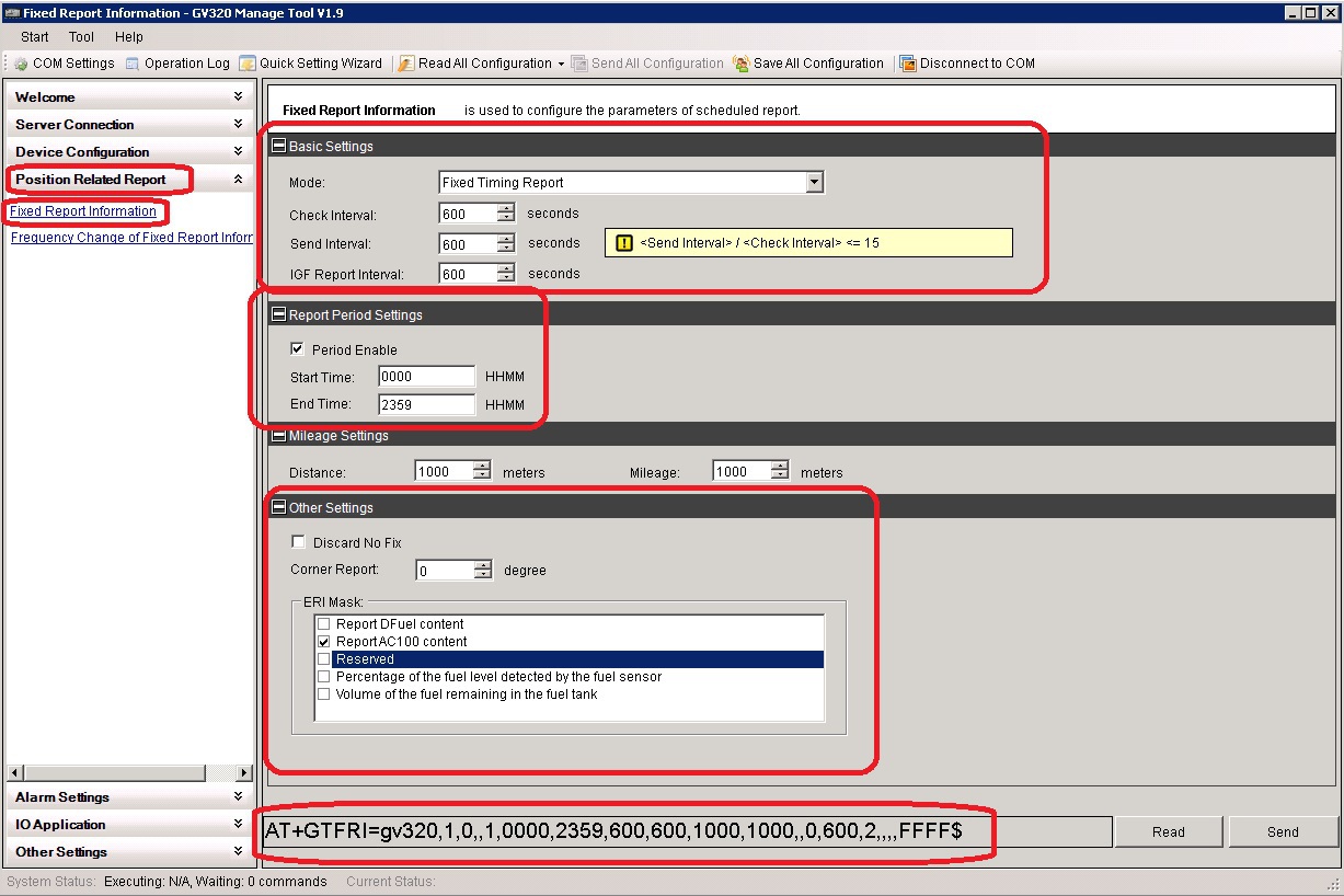
Setting the mode for issuing by the tracker extended messages using SMS for the GV300 tracker:
send from your phone to the SIM card number in the tracker a message with the following text: AT + GTFRI = gv300,1,0, 1,0000,2359,600,600,1000,1000,, 0,600,2 ,,,, FFFF $
Setup mode for the tracker to issue extended messages using SMS for the GV320 tracker:
send a message with the following text from your phone to the SIM card number in the tracker: AT + GTFRI = gv320,1,0,, 1,0000,2359,600,600,1000,1000 ,, 0,600,2 ,,,, FFFF $
If the authorization mode for smart cards is enabled, the tracker will not issue messages to the server when the iButton key touches the reader.
Authorization settings are configured using the AT + GTIDA command. It allows you to allow or prohibit the use of authorization, configure the mode of sending authorization messages, create a list with ID numbers of smart cards, set the time interval during which re-authorization will not be necessary, and also assign a digital output that will control an external relay, contacts which can be used to de-energize the starter or fuel pump. However, all these features are not used when working with iButton keys and authorization must be disabled.
Setting authorization parameters using the Manage Tool:
- in the command browser (left panel of the Manage Tool program) select the item Other Settings;
- in the command browser select the sub-item ID authentication;
- in the command settings panel, set the parameter Mode:
Mode: Disable this function.

Setting authorization parameters using the GV300 SMS tracker:
send a message with the following text from your phone to the SIM card number in the tracker: AT + GTIDA = gv300,0,1,1,, 30,0,30 ,,,, 0,0 , 0,0 ,,,,, FFFF $
Setting authorization parameters using the GV320 SMS tracker:
send a message with the following text from your phone to the SIM card number in the tracker: AT + GTIDA = gv320,0,1,1,, 30 , 0.30 ,,,, 0.0.0.0 ,,,,, FFFF $
The connection diagram for the temperature sensor and the iButton reader is shown in the figure below:

To ensure greater noise immunity, it is necessary to place the AC100 converter next to the tracker so that the length of the wires between them is no more than 50 centimeters. The AC100 power wire (VCC-AC100) must be connected to the pin 11 wire of the GV300 / GV320 tracker so that the total length of the wire through which the tracker supply current and AC100 supply current flows is as short as possible, no longer than 10 centimeters. Similarly, you need to connect the GND-AC100 common wire to pin 6 of the GV300 / GV320 tracker connector.
It is possible to use a free resource as a navigation server (up to 5 monitoring objects):
GPS Trace Orange
+ RESP: GTERI, 0E0402,861074023811477,, 00000002,, 10,1,1,0.0,0,133.4, 37.656057,55.847563 , 20,150,924,144,740,
0250,0099,6C25,82DC, 00,0.0 ,,,, 0,210104,2, 1 , 28709C400400006E , 1 , 01A9,20150924175108,00B2 $
Here, in a separate font are highlighted:
37.656057,55.847563 - coordinates of the tracker
1 - number of the temperature sensor, there can be two in total;
28709C400400006E - ID of the temperature sensor;
1 - type of temperature sensor;
01A9- representation of temperature value, number in hexadecimal format. To calculate the true temperature in degrees Celsius, you need to convert it to decimal format and multiply by 0.0625. That is:
01A9 (HEX) = 0 * 4096 + 1 * 256 + 10 * 16 + 9 * 1 = 256 + 160 + 9 = 425 (DEC)
425 * 0.0625 = 26.5625≈26.6 degrees Celsius.
+ RESP: GTIDA, 0E0402.861074023811477 ,,, 012ACBB80C000020 , 0.1.0.0.0.0.133.4, 37.656057.55.847563 , 20150924145755,
0250.0099.6C25.82DC, 00.0.0 ,,,,, 20150924175756,00B3 $
Here in a separate font:
012ACBB80C000020 - iButton key ID,
37.656057,55.847563 - tracker coordinates
The temperature sensor and iButton reader are connected to the tracker via an additional interface conversion device (1-Wire / RS232-UART) of the AC100 type. The AC100 is part of the 1-Wire Temperature Sensor Kits (kit with temperature sensor) and iButton Kits (kit with iButton key reader). To connect the AC100, the serial port RS232-UART of the GV300 / GV320 trackers is used.
1-Wire Temperature Sensor Kits
iButton Kits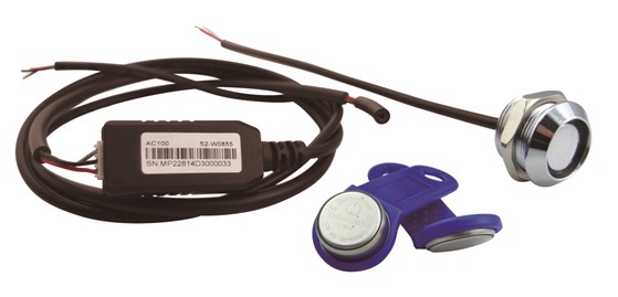
To use the iButton temperature sensor and reader with the GV300 / GV320 tracker, you must:
- check the version of the tracker firmware and update it if necessary
- configure the tracker to work with the temperature sensor and iButton reader (description in the GV300 Track Air Interface Protocol V6.03 and GV320 Track Air Interface Protocol V4.02 documents)
- connect the temperature sensor and iButton reader to the AC100
- connect the AC100 to the tracker
1. Checking the tracker firmware version
You can find out the firmware version by connecting the tracker to a computer and running a special program for setting up trackers - the Manage Tool. Select the Help menu, then About. In the window that appears, you can see the line with the firmware version in the tracker, for example this: Device Version: GV320R00A14V08M128_NMX Firmware
versions that support operation with the temperature sensor and iButton reader:
for GV300 - GV300R00A07V15M128_NMX and higher;
for GV320M1281212 and
firmware version GV320X12A12 and later then you need to update it. Instructions for updating the firmware in the tracker are given in the corresponding document (GV300 Track Air Interface Firmware Update V1.00 and GV320 Track Air Interface Firmware Update V1.00).
2. Configuring the tracker to work with the temperature sensor and iButton reader
To work with the temperature sensor and iButton reader, you need to configure the following tracker parameters:
- parameters and operation mode of the RS232-UART serial port,
- AC100 operation mode
- enable extended message mode
- disable smart card authorization.
You can configure the tracker using the Manage Tool program or by sending several SMS messages with the appropriate commands to the tracker's SIM card number.
Together with the tracker, you can use one iButton reader and up to two temperature sensors. After connecting new temperature sensors, it is necessary to restart the tracker to correctly determine them.
2.1 Configuring the parameters and operating mode of the RS232-UART serial port of the tracker
To configure the serial port of the tracker, use the AT + GTURT command.
It determines what external device the UART port will work with, the exchange rate and the number of data bits, stop bits and the use of the parity bit in the package, and also whether the power saving mode is enabled or disabled and the use of digital input number 1 to enable or disable this mode.
If you enable the power saving mode, the response of the tracker to UART will become slow and to ensure a normal reaction, you must enable the tracker to wake up by affecting digital input 1 (Input ID of Wakeup: Use digital input 1 to wakeup the device).
Configuring UART using the Manage Tool:
- in the command browser (left panel of the Manage Tool) select Other Settings;
- in the command browser select the sub-item Serial Port Setting;
- in the command settings panel, set them as follows:
Working Mode: Used for AC100 devices
Baudrate Index: 115200
Data Bits: 8
Parity Bits: None Parity
Stop Bits: 1
Sleep Enable: Disable the device sleep and the serial port sleep mode
Input ID of Wakeup: Do not use digital input to wakeup the device
Configuring the GV300 UART2 tracker using SMS:
send a message with the following text from your phone to the SIM card number in the tracker: AT + GTURT = gv300,5,12,8, 1,0,2,0 ,,, FFFF $
Configuring the GV320 UART2 tracker using SMS:
send a message with the following text from your phone to the SIM card number in the tracker: AT + GTURT = gv320,5,12,8,1,0,2,0 ,,, FFFF $
2.2 Setting the operating mode of the AC100
The operation mode of the AC100 is set by the AT + GTACD command.
Setting the operating mode of the AC100 converter using the Manage Tool program:
- in the command browser (left panel of the Manage Tool program) select Other Settings;
- in the command browser select the sub-item AC100 Devices Setting;
- in the command settings panel, set them as follows:
I-button timer: 1 seconds
Temperature timer: 10 seconds
Output ID: 3
Out Status: check or uncheck
Duration: 0 x100ms
Toggle Times: 0
Comments on the parameters of the mode settings command AC100 converter operation:
- I-button timersets the time interval for polling the iButton key reader from 1 to 10 seconds; if set to 0, the reader will not be polled;
- The temperature timer sets the time interval for polling temperature sensors from 10 to 255 seconds; if set to 0, the sensor will not be polled;
- Output ID sets the number of the digital output on which the pulse signal will be generated if a key is attached to the reader. If Output ID = 0, then no digital output will be used to generate a pulse;
- Duration sets the pulse duration from 0 to 255 times 0.1 sec .;
- Toggle Timessets the number of pulses that will be generated at the output from 0 to 255;
- Output Status is used only when Duration = 0 and Toggle Times = 0 and determines the state of the digital output after the key has been touched by the reader. If Output Status 0, then the digital output is turned off, and if Output Status = 1, then the digital output is turned on, and it remains in this state all the time until the power to the tracker is turned off.
Setting the operating mode of the AC100 converter using SMS for the GV300 tracker:
send a message with the following text from your phone to the SIM card number in the tracker: AT + GTACD = gv300,1,3,0,0,0,10 ,,,,, Ffff $
Setting the operation mode of the AC100 converter using SMS for the GV320 tracker:
send a message with the following text from your phone to the SIM card number in the tracker: AT + GTACD = gv320,1,3,0,0,0,10 ,,,,, Ffff $
2.2.1 Additional features for the user with the iButton key
The iButton key can be used to turn off the ignition in the car. To do this, make the following settings:
AT + GTACD = gv320,1,3,0,0,0,0 ,,,,,, FFFF $
AT + GTOUT = gv320,0 ,,, 0,0,0,1,0 , 0,0,, 0,0 ,,,, FFFF $
And connect the relay switching the ignition circuit to digital output number 3.After applying power to the tracker, it will turn on digital output 3, this will turn on the relay and power from the battery through the closed contacts of the relay will go to the ignition switch of the car. If you now touch the reader with the iButton key, the tracker will turn off output 3. The relay will also turn off, its contacts will open and the ignition will be de-energized. Further touches with the key to the reader will lead to nothing, the off state will remain until the next shutdown and on or restart of the tracker.
2.3 Enabling the mode of issuing tracker extended messages
The temperature value is issued by the tracker to the server in the message + RESP: GTERI (extended message about fixing coordinates). To configure the tracker in the mode of issuing such messages, you need to set equal to 1 bit number 1 in the bit mask of the ERI Mask of the AT + GTFRI command.
Setting the mode for issuing extended messages by the tracker using the Manage Tool:
- select the Position Related Report item in the command browser (left panel of the Manage Tool program),
- select the Fixed Report Information sub-item in the command browser,
- check the ERI Mask in the command settings panel checkmark option:
Report AC100 content
Setting the mode for issuing by the tracker extended messages using SMS for the GV300 tracker:
send from your phone to the SIM card number in the tracker a message with the following text: AT + GTFRI = gv300,1,0, 1,0000,2359,600,600,1000,1000,, 0,600,2 ,,,, FFFF $
Setup mode for the tracker to issue extended messages using SMS for the GV320 tracker:
send a message with the following text from your phone to the SIM card number in the tracker: AT + GTFRI = gv320,1,0,, 1,0000,2359,600,600,1000,1000 ,, 0,600,2 ,,,, FFFF $
2.4 Disabling smart card authorization
If the authorization mode for smart cards is enabled, the tracker will not issue messages to the server when the iButton key touches the reader.
Authorization settings are configured using the AT + GTIDA command. It allows you to allow or prohibit the use of authorization, configure the mode of sending authorization messages, create a list with ID numbers of smart cards, set the time interval during which re-authorization will not be necessary, and also assign a digital output that will control an external relay, contacts which can be used to de-energize the starter or fuel pump. However, all these features are not used when working with iButton keys and authorization must be disabled.
Setting authorization parameters using the Manage Tool:
- in the command browser (left panel of the Manage Tool program) select the item Other Settings;
- in the command browser select the sub-item ID authentication;
- in the command settings panel, set the parameter Mode:
Mode: Disable this function.
Setting authorization parameters using the GV300 SMS tracker:
send a message with the following text from your phone to the SIM card number in the tracker: AT + GTIDA = gv300,0,1,1,, 30,0,30 ,,,, 0,0 , 0,0 ,,,,, FFFF $
Setting authorization parameters using the GV320 SMS tracker:
send a message with the following text from your phone to the SIM card number in the tracker: AT + GTIDA = gv320,0,1,1,, 30 , 0.30 ,,,, 0.0.0.0 ,,,,, FFFF $
3. Connecting the temperature sensor and iButton key reader to the GV300 / GV320 trackers
The connection diagram for the temperature sensor and the iButton reader is shown in the figure below:
To ensure greater noise immunity, it is necessary to place the AC100 converter next to the tracker so that the length of the wires between them is no more than 50 centimeters. The AC100 power wire (VCC-AC100) must be connected to the pin 11 wire of the GV300 / GV320 tracker so that the total length of the wire through which the tracker supply current and AC100 supply current flows is as short as possible, no longer than 10 centimeters. Similarly, you need to connect the GND-AC100 common wire to pin 6 of the GV300 / GV320 tracker connector.
4. Examples of messages sent to the server by the tracker
It is possible to use a free resource as a navigation server (up to 5 monitoring objects):
GPS Trace Orange
a) Temperature and temperature sensor ID is issued to the server in a GTERI message:
+ RESP: GTERI, 0E0402,861074023811477,, 00000002,, 10,1,1,0.0,0,133.4, 37.656057,55.847563 , 20,150,924,144,740,
0250,0099,6C25,82DC, 00,0.0 ,,,, 0,210104,2, 1 , 28709C400400006E , 1 , 01A9,20150924175108,00B2 $
Here, in a separate font are highlighted:
37.656057,55.847563 - coordinates of the tracker
1 - number of the temperature sensor, there can be two in total;
28709C400400006E - ID of the temperature sensor;
1 - type of temperature sensor;
01A9- representation of temperature value, number in hexadecimal format. To calculate the true temperature in degrees Celsius, you need to convert it to decimal format and multiply by 0.0625. That is:
01A9 (HEX) = 0 * 4096 + 1 * 256 + 10 * 16 + 9 * 1 = 256 + 160 + 9 = 425 (DEC)
425 * 0.0625 = 26.5625≈26.6 degrees Celsius.
b) When the iButton key touches the reader, the GTIDA message is displayed on the server:
+ RESP: GTIDA, 0E0402.861074023811477 ,,, 012ACBB80C000020 , 0.1.0.0.0.0.133.4, 37.656057.55.847563 , 20150924145755,
0250.0099.6C25.82DC, 00.0.0 ,,,,, 20150924175756,00B3 $
Here in a separate font:
012ACBB80C000020 - iButton key ID,
37.656057,55.847563 - tracker coordinates
Brief characteristics of the temperature sensor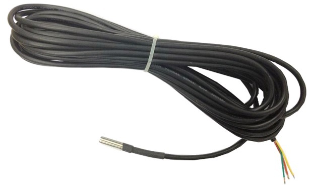
The temperature sensor for Queclink GVxxx car trackers is a small metal sleeve with a cable length of 8 meters. Inside the metal sleeve is a DS18B20 temperature converter chip. The sensor cable has three wires and can be mounted either by soldering or using terminal blocks. A detailed description of the temperature sensor and its technical characteristics are given in the document 1-Wire Temp Sensor User Guide V1.0
Color marking of the temperature sensor wires:

The temperature sensor for Queclink GVxxx car trackers is a small metal sleeve with a cable length of 8 meters. Inside the metal sleeve is a DS18B20 temperature converter chip. The sensor cable has three wires and can be mounted either by soldering or using terminal blocks. A detailed description of the temperature sensor and its technical characteristics are given in the document 1-Wire Temp Sensor User Guide V1.0
Color marking of the temperature sensor wires:
Brief characteristics of the iButton key reader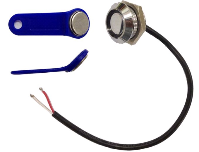
The iButton key reader is a metal contact device with a short two-wire cable length of 18 cm, the reader can be fixed with a nut on the front panel, and the cable can also be mounted either by soldering or using terminal blocks. A full description of the iButton key reader is given in the 1-Wire iButton User Guide V2.0
Color Code for the iButton Key Reader Wires:

The iButton key reader is a metal contact device with a short two-wire cable length of 18 cm, the reader can be fixed with a nut on the front panel, and the cable can also be mounted either by soldering or using terminal blocks. A full description of the iButton key reader is given in the 1-Wire iButton User Guide V2.0
Color Code for the iButton Key Reader Wires:
Summary of AC100 Interface Converter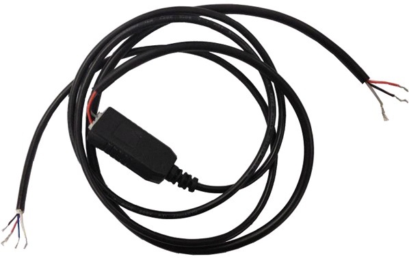
The AC100 is designed to match the RS232 interface with the 1-Wire interface. The converter has two cables, one with four wires, it is designed to connect the converter to the tracker and the second with three, for connecting a temperature sensor and / or iButton reader to the converter.
Color marking of the cable wires for connecting the AC100 converter to the tracker:

Color marking of the cable wires for connecting the temperature sensor and iButton reader to the AC100 converter:

The AC100 is designed to match the RS232 interface with the 1-Wire interface. The converter has two cables, one with four wires, it is designed to connect the converter to the tracker and the second with three, for connecting a temperature sensor and / or iButton reader to the converter.
Color marking of the cable wires for connecting the AC100 converter to the tracker:
Color marking of the cable wires for connecting the temperature sensor and iButton reader to the AC100 converter:
Summary of Queclink GV300 / GV320
Размеры: 80х49х26 мм
Вес: 60 г
Резервная батарея: литий-полимерная емкостью 250 мАч
Диапазон напряжений питания: от 8 В до 32 В
Диапазоны температур:
рабочая -30°С до +80°С (без резервной батареи)
Четыре диапазона 850/900/1800/1900 МГц (GV300)
Два диапазона 900/1800 МГц (GV320)
GPS/GNSS чипсет: u-blox (UBX-G6010)
Комплект поставки: трекер и интерфейсный кабель
Кабель data_cable_m для конфигурирования трекера через ПК с помощью ПО Manage Tool поставляется отдельно:

Документация:
GV300 Track Air Interface Protocol V6.03, GV300 Track Air Interface Firmware Update V1.00;
GV320 Track Air Interface Protocol V4.02, GV320 Track Air Interface Firmware Update V1.00;
1-Wire Temp Sensor User Guide V1 0 , 1-Wire iButton User Guide V2.0 ;
Tracker configuration software (only for Windows 98SE, Windows ME, Windows 2000 SP4, Windows XP SP2 and above (32 & 64 bit), Windows Server 2003 (32 & 64 bit), Windows Server 2008 (32 & 64 bit), Windows Vista (32 & 64 bit)):
Queclink_GV300_Manage_Tool_V2.6
Queclink_GV320_Manage_Tool_V1.9
Вес: 60 г
Резервная батарея: литий-полимерная емкостью 250 мАч
Диапазон напряжений питания: от 8 В до 32 В
Диапазоны температур:
рабочая -30°С до +80°С (без резервной батареи)
Четыре диапазона 850/900/1800/1900 МГц (GV300)
Два диапазона 900/1800 МГц (GV320)
GPS/GNSS чипсет: u-blox (UBX-G6010)
Комплект поставки: трекер и интерфейсный кабель
Кабель data_cable_m для конфигурирования трекера через ПК с помощью ПО Manage Tool поставляется отдельно:
Документация:
GV300 Track Air Interface Protocol V6.03, GV300 Track Air Interface Firmware Update V1.00;
GV320 Track Air Interface Protocol V4.02, GV320 Track Air Interface Firmware Update V1.00;
1-Wire Temp Sensor User Guide V1 0 , 1-Wire iButton User Guide V2.0 ;
Tracker configuration software (only for Windows 98SE, Windows ME, Windows 2000 SP4, Windows XP SP2 and above (32 & 64 bit), Windows Server 2003 (32 & 64 bit), Windows Server 2008 (32 & 64 bit), Windows Vista (32 & 64 bit)):
Queclink_GV300_Manage_Tool_V2.6
Queclink_GV320_Manage_Tool_V1.9