September 10, 2015 at 07:26
Clocking Atmel SAMD20 / 21 Microcontrollers
Bit of theory
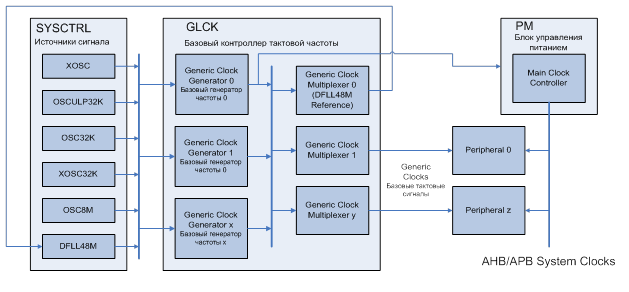
According to the documentation for Atmel microcontrollers of the SAMD20 / 21 series, the clock system consists of the following blocks:
- signal source block (controlled by SYSCTRL)
- Clock source is the base frequency in the system. This can be, for example, an internal 8 MHz oscillator (OSC8M), an external oscillator (XOSC), a digital phase-locked loop (DFLL48M);
- GLCK-generic clock controller, which controls the clock distribution system and consists of:
- basic frequency generators (Generic Clock Generator) is a programmable prescaler to which any signal source can be connected. From the output of generator 0 (GCLKGEN [0], GCLK_MAIN), the signal goes to the Power manager, which generates the main clock signal;
- basic clock signals (Generic Clocks) - usually these are signals that clock the periphery. Basic clocks, using basic signal multiplexers, can use any of the clocks available in the system. Different peripheral units may use different clock signals. The output of multiplexer 0 is used as a reference signal source for a digital phase locked loop. Please note that in this case, the output from DFLL should not be used as a reference signal for a generator whose output is used as a reference for multiplexer 0.
- power management unit (PM - Power manager)
- the power management unit controls the synchronized timing of the system. This includes the CPU, buses (APB, AHB) and synchronous (in terms of CPU) peripherals. It contains clock masks with which you can turn the peripheral user interface on and off, as well as dividers for CPU clock signals, buses.
The periphery can be clocked simultaneously with 2 clock signals:
- synchronous from Power Manager (provides peripheral work with CPU via APB / AHB bus);
- asynchronous from GCLK (provides the work of the "core" of the periphery).
The synchronization between these two clock signals is implemented in hardware. And even if the frequencies and signal sources are the same, synchronization still occurs.
All registers clocked at the same frequency and source as the buses do not require synchronization. All registers of the "core" require synchronization when writing, and some when reading.
The synchronization process is indicated by the SYNCBUSY bit in the status register or by interrupt.
Thus, in theory, to configure the clock signals you need:
- Select the base source (or several) of the reference clock signal: it can be an external oscillator, internal, etc. (SYSCTRL block)
- Set up a pre-divider and multiplexer for each of the basic signals (GCLK block).
- Select the main clock signal (output from generator 0).
- Set up clock peripherals (generic clocks).
For correct work with clock signals, you need to look into the electrical characteristics at the end of the datasheet, since there are a lot of interesting things. In particular:
- The reference clock for DFLL can be:
- minimum value: 0.732 kHz
- typical value: 32.768 kHz
- maximum value: 35.1 kHz
- DFLL output: 47 to 49 MHz
- external generator should be: no more than 32 MHz.
How is the code in ASF
We will not go into the details of the entire library, this can be found in the article about ASF . Consider only timing. When creating a project in Atmel Studio, the main.c file is created , which already contains system_init () .
The prototype of this function is located in the src / asf / sam0 / system / system.c file :
/**
 * \brief Initialize system.
 *
 * This function will call the various initialization functions within the
 * system namespace. If a given optional system module is not available, the
 * associated call will effectively be a NOP (No Operation).
 *
 * Currently the following initialization functions are supported:
 *  - System clock initialization (via the SYSTEM CLOCK sub-module)
 *  - Board hardware initialization (via the Board module)
 *  - Event system driver initialization (via the EVSYS module)
 *  - External Interrupt driver initialization (via the EXTINT module)
 */
void system_init(void)
{
	/* Configure GCLK and clock sources according to conf_clocks.h */
	system_clock_init();
	/* Initialize board hardware */
	system_board_init();
	/* Initialize EVSYS hardware */
	_system_events_init();
	/* Initialize External hardware */
	_system_extint_init();
}
We are interested in system_clock_init () , which, in turn, is defined in clock.c .
In general, the code for this function is made entirely on defines from asf / config / conf_clocks.h . Therefore, you can not understand much, rather just for fun to see.
But all the configuration takes place in conf_clocks.h in accordance with the plan given above.
Practice
Let's look at an example. Suppose we have a board with MK SAM20 / 21, which is clocked from an external quartz 7.3728 MHz, and we want to get a system clock of 48 MHz.
We must all set up as shown in the orange arrows in the figure below:
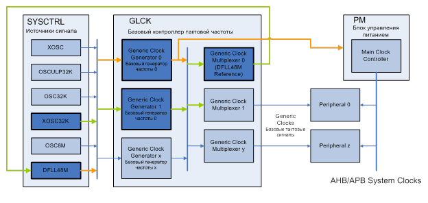
Ie the base oscillator 1 must have a clock signal from an external quartz at the input, which must be divided up to a frequency acceptable for DFLL (from 0.7 to 35 kHz). DFLL must be enabled, the appropriate reference signal for it and the multiplication factor selected in order to get something close to 48 MHz at the output. The output of the DFLL should be set to the base generator 0.
Calculation of the division and multiplication factors.
In order to get an acceptable reference clock signal for DFLL, the signal from an external oscillator needs to be strongly divided:
7.3728MHz / 256 = 28.8 kHz
And the multiplication coefficient for DFLL is determined based on the input (reference frequency) and the desired output frequency:
28.8 * 1666 = 47.980800 MHz
Now we will consider how to do this in conf_clocks.h .
We enable clocking from an external source and specify its parameters:
// SYSTEM_CLOCK_SOURCE_XOSC configuration - External clock/oscillator
#  define CONF_CLOCK_XOSC_ENABLE                  true
#  define CONF_CLOCK_XOSC_EXTERNAL_CRYSTAL        SYSTEM_CLOCK_EXTERNAL_CRYSTAL
#  define CONF_CLOCK_XOSC_EXTERNAL_FREQUENCY      7372800UL
#  define CONF_CLOCK_XOSC_STARTUP_TIME            SYSTEM_XOSC_STARTUP_32768
#  define CONF_CLOCK_XOSC_AUTO_GAIN_CONTROL       true
#  define CONF_CLOCK_XOSC_ON_DEMAND               true
#  define CONF_CLOCK_XOSC_RUN_IN_STANDBY          false
Enable DFLL:
// SYSTEM_CLOCK_SOURCE_DFLL configuration - Digital Frequency Locked Loop
#  define CONF_CLOCK_DFLL_ENABLE                  true
#  define CONF_CLOCK_DFLL_LOOP_MODE               SYSTEM_CLOCK_DFLL_LOOP_MODE_CLOSED
#  define CONF_CLOCK_DFLL_ON_DEMAND               false
Configure DFFL (reference frequency source and multiplication factor):
// DFLL closed loop mode configuration
#  define CONF_CLOCK_DFLL_SOURCE_GCLK_GENERATOR   GCLK_GENERATOR_1
#  define CONF_CLOCK_DFLL_MULTIPLY_FACTOR         1666
#  define CONF_CLOCK_DFLL_QUICK_LOCK              true
#  define CONF_CLOCK_DFLL_TRACK_AFTER_FINE_LOCK   true
#  define CONF_CLOCK_DFLL_KEEP_LOCK_ON_WAKEUP     true
#  define CONF_CLOCK_DFLL_ENABLE_CHILL_CYCLE      true
#  define CONF_CLOCK_DFLL_MAX_COARSE_STEP_SIZE    (0x1f / 4)
#  define CONF_CLOCK_DFLL_MAX_FINE_STEP_SIZE      (0xff / 4)
We configure the generators 0 and 1 (we allow the work, select the reference frequency):
// Set this to true to configure the GCLK when running clocks_init. If set to
// false, none of the GCLK generators will be configured in clocks_init().
#  define CONF_CLOCK_CONFIGURE_GCLK               true
// Configure GCLK generator 0 (Main Clock)
#  define CONF_CLOCK_GCLK_0_ENABLE                true
#  define CONF_CLOCK_GCLK_0_RUN_IN_STANDBY        false
#  define CONF_CLOCK_GCLK_0_CLOCK_SOURCE          SYSTEM_CLOCK_SOURCE_DFLL
#  define CONF_CLOCK_GCLK_0_PRESCALER             1
#  define CONF_CLOCK_GCLK_0_OUTPUT_ENABLE         false
// Configure GCLK generator 1
#  define CONF_CLOCK_GCLK_1_ENABLE                true
#  define CONF_CLOCK_GCLK_1_RUN_IN_STANDBY        false
#  define CONF_CLOCK_GCLK_1_CLOCK_SOURCE          SYSTEM_CLOCK_SOURCE_XOSC
#  define CONF_CLOCK_GCLK_1_PRESCALER             256
#  define CONF_CLOCK_GCLK_1_OUTPUT_ENABLE         false
Stock
For those who are most attentive, we are pleased to announce that Rainbow is renewing its action on the free distribution of ATSAMD20G16A-AU microcontrollers for radio amateurs (and not only):
After receiving and processing the application, we will contact you and explain where and when to take the samples (NEAD).
- Samples are provided free of charge, subject to pickup from the Rainbow Moscow office.
- 2 microcontrollers in one hand are provided
- To participate in the action it is necessary to send an application for receiving samples to [email protected] indicating brief information about yourself and the intended use of microcontrollers (name and contact details, 3-5 sentences of the project description)
- Special offers are offered to participants. the price of an evaluation board of the SAM D20 series with the integrated debugger ATSAMD20-XPRO is 1000 rubles (the number of boards is limited)
After receiving and processing the application, we will contact you and explain where and when to take the samples (NEAD).
Done!