November 23, 2015 at 17:55
Signal phase shift to VHDL
This article is a continuation of the topic series. Delay element on VHDL , Delay element on VHDL. Another look at VHDL delay elements implemented in FPGAs.
The emphasis will be on a specific applied example, which anyone can run in a simulator or real hardware. The example was created for convenient simulation in the Xilinx ISE environment using Modelsim SE and, with minimal changes, it is implemented in a full-fledged IP Core.
Carry out a phase shift of the pulse signal by a predetermined value (the pulse duration is arbitrary), possibly not synchronous with the frequency of the core logic. Do this without rebooting or shutting down the module / device.
DIP switch of 8 positions at which the delay code in the binary code is set (shift value). Hard or Soft Reset - initial reset, setting default parameters. The reference frequency is 100 MHz, i.e. 10 ns minimum offset time.
I will call the logical unit 1 as the
impulse . Pause, the logical zero is 0.
The code is implemented as a state machine, which, in my opinion, thanks to the step-by-step structure and the ability to give a distinct name to each stage, is very simple and understandable.
In addition to comments on the code, the testbench simulation file is included.
State Machine Diagram:
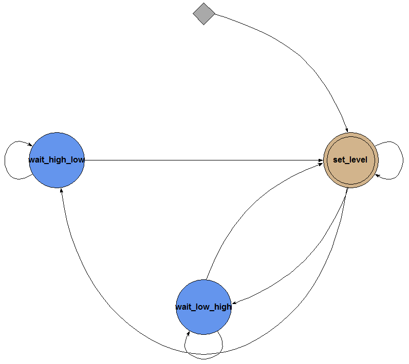
Basic Logic. The code monitors the change in the signal level, then the counter starts when its value becomes equal to the set shift, the same level is output as it is monitored in a circle.
Simulation Code for Modelsim:
An experienced electronics engineer could notice the shortcomings of this code, namely. The set delay should not exceed:
- the pulse duration, if the pulse duration is less than the pause duration;
- the duration of the pause if the duration of the pause is less than the duration of the pulse.
Those. the magnitude of the phase shift should not exceed 180 ° for both 0 and 1 in the case of a pulse signal.
In the diagram below you can see how the phase shift of the input signal by 40 ns in real time, with a delay in the logic operation, is carried out:

Next is a demonstration of the situation if the tuned signal and the reference frequency are asynchronous: I

suggest that you analyze this situation and draw your own conclusions .
I will be glad to hear your comments and comments, with the help of which in the next article, this code will be supplemented with new functionality.
Thanks for attention.
The emphasis will be on a specific applied example, which anyone can run in a simulator or real hardware. The example was created for convenient simulation in the Xilinx ISE environment using Modelsim SE and, with minimal changes, it is implemented in a full-fledged IP Core.
Formulation of the problem
Carry out a phase shift of the pulse signal by a predetermined value (the pulse duration is arbitrary), possibly not synchronous with the frequency of the core logic. Do this without rebooting or shutting down the module / device.
Instruments
DIP switch of 8 positions at which the delay code in the binary code is set (shift value). Hard or Soft Reset - initial reset, setting default parameters. The reference frequency is 100 MHz, i.e. 10 ns minimum offset time.
Implementation
I will call the logical unit 1 as the
impulse . Pause, the logical zero is 0.
The code is implemented as a state machine, which, in my opinion, thanks to the step-by-step structure and the ability to give a distinct name to each stage, is very simple and understandable.
In addition to comments on the code, the testbench simulation file is included.
State Machine Diagram:
Basic Logic. The code monitors the change in the signal level, then the counter starts when its value becomes equal to the set shift, the same level is output as it is monitored in a circle.
freq_shift_half_cycle.vhd
library ieee;
use ieee.std_logic_1164.all;
use ieee.numeric_std.all;
use ieee.std_logic_arith.all;
use ieee.std_logic_unsigned.all;
entity freq_shift_half_cycle is
    Port (
			  Bus2IP_Clk          : in  STD_LOGIC;                     -- частота работы логики
           Bus2IP_Reset        : in  STD_LOGIC;                     -- сброс
           Clk_in              : in  STD_LOGIC;                     -- входной сигнал
           Shift_reg           : in  STD_LOGIC_VECTOR (7 downto 0); -- знчение задержки в тактах Bus2IP_Clk
           counter_reg_test    : out STD_LOGIC_VECTOR (7 downto 0); -- тестовый счетчик
           Clk_out             : out STD_LOGIC                      -- выходной сигнал
			  );
end freq_shift_half_cycle;
architecture Behavioral of freq_shift_half_cycle is
type state_type is (set_level, wait_high_low, wait_low_high); -- описание машины состояний
signal current_stage  : state_type;
signal counter_shift  : STD_LOGIC_VECTOR (7 downto 0); -- внутренний счетчик
begin
shift_fsm : process (Bus2IP_Reset, Bus2IP_Clk, Clk_in, Shift_reg)
begin
	if Shift_reg = x"00" or Bus2IP_Reset = '1' then    -- если задержка нулевая или подан reset
		Clk_out       <= Clk_in;
		counter_shift <= x"01";
		counter_reg_test <= x"01";                      -- тестовый счетчик
		current_stage <= set_level;
	elsif (Bus2IP_Clk'event and Bus2IP_Clk = '1') then
		case current_stage is
			when set_level =>
				if counter_shift = Shift_reg   then        -- после выставленной задержки, подаём на выход 0 или 1
					if Clk_in = '1' then
						Clk_out       <= '1';
						current_stage <= wait_high_low;
					else
						Clk_out       <= '0';
						current_stage <= wait_low_high;
					end if;
					counter_shift    <= x"01";
					counter_reg_test <= x"01";              -- тестовый счетчик
				elsif counter_shift < Shift_reg   then
					counter_shift    <= counter_shift + 1;
					counter_reg_test <= counter_shift + 1;  -- тестовый счетчик
					current_stage    <= set_level;
				end if;
			when wait_high_low =>                   -- ждем переключения 1 на 0 и возвращаемся в set_level
				if Clk_in = '1' then
					current_stage <= wait_high_low;
				else
					current_stage <= set_level;
				end if;
			when wait_low_high =>                   -- ждем переключения 0 на 1 и возвращаемся в set_level
				if Clk_in = '0' then
					current_stage <= wait_low_high;
				else
					current_stage <= set_level;
				end if;
			when others =>
				current_stage    <= set_level;
		end case;
	end if;
end process shift_fsm;
end Behavioral;
Simulation Code for Modelsim:
testbench_half_cycle.vhd
LIBRARY ieee;
USE ieee.std_logic_1164.ALL;
-- Uncomment the following library declaration if using
-- arithmetic functions with Signed or Unsigned values
--USE ieee.numeric_std.ALL;
ENTITY testbench_half_cycle IS
END testbench_half_cycle;
ARCHITECTURE behavior OF testbench_half_cycle IS
    -- Component Declaration for the Unit Under Test (UUT)
    COMPONENT freq_shift_half_cycle
    PORT(
         Bus2IP_Clk : IN  std_logic;
         Bus2IP_Reset : IN  std_logic;
         Clk_in : IN  std_logic;
         Shift_reg : IN  std_logic_vector(7 downto 0);
         counter_reg_test : OUT  std_logic_vector(7 downto 0);
         Clk_out : OUT  std_logic
        );
    END COMPONENT;
   --Inputs
   signal Bus2IP_Clk : std_logic := '0';
   signal Bus2IP_Reset : std_logic := '0';
   signal Clk_in : std_logic := '0';
   signal Shift_reg : std_logic_vector(7 downto 0) := (others => '0');
 	--Outputs
   signal counter_reg_test : std_logic_vector(7 downto 0);
   signal Clk_out : std_logic;
   -- Clock period definitions
   constant Bus2IP_Clk_period : time := 10 ns;
   constant Clk_in_period : time := 100 ns;
BEGIN
	-- Instantiate the Unit Under Test (UUT)
   uut: freq_shift_half_cycle PORT MAP (
          Bus2IP_Clk => Bus2IP_Clk,
          Bus2IP_Reset => Bus2IP_Reset,
          Clk_in => Clk_in,
          Shift_reg => Shift_reg,
          counter_reg_test => counter_reg_test,
          Clk_out => Clk_out
        );
   -- Clock process definitions
   Bus2IP_Clk_process :process
   begin
	Bus2IP_Clk <= '1';
	wait for Bus2IP_Clk_period/2;
	Bus2IP_Clk <= '0';
	wait for Bus2IP_Clk_period/2;
   end process;
   Clk_in_process :process
   begin
	Clk_in <= '1';
	 wait for Clk_in_period/2;
	 Clk_in <= '0';
	 wait for Clk_in_period/2;
        --  wait for 1000 ns;
  end process;
   -- Stimulus process
   stim_proc: process
   begin
      -- hold reset state for 100 ns.
		Bus2IP_Reset <= '1';
                wait for 500 ns;
		Bus2IP_Reset <= '0';
		wait for 5000 ns;
		Shift_reg <= x"01";   -- выставляется задержка
		wait for 5000 ns;
		Shift_reg <= x"00";
		wait for 5000 ns;
		Shift_reg <= x"04";
      wait for Bus2IP_Clk_period*10;
      -- insert stimulus here
      wait;
   end process;
END;
An experienced electronics engineer could notice the shortcomings of this code, namely. The set delay should not exceed:
- the pulse duration, if the pulse duration is less than the pause duration;
- the duration of the pause if the duration of the pause is less than the duration of the pulse.
Those. the magnitude of the phase shift should not exceed 180 ° for both 0 and 1 in the case of a pulse signal.
In the diagram below you can see how the phase shift of the input signal by 40 ns in real time, with a delay in the logic operation, is carried out:
Next is a demonstration of the situation if the tuned signal and the reference frequency are asynchronous: I
suggest that you analyze this situation and draw your own conclusions .
I will be glad to hear your comments and comments, with the help of which in the next article, this code will be supplemented with new functionality.
Thanks for attention.