October 14, 2015 at 12:48
WebGL Oscilloscope
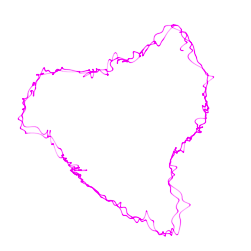
There is an interesting direction in electronic music - music for oscilloscopes, which draws interesting pictures if you connect the output of an audio card to an oscilloscope in XY mode.
For example, Youscope , Oscillofun and Khrậng .
All the beautiful videos generated by such music are created by recording the work of a real oscilloscope on a video camera. When I searched the network for oscilloscope emulators, I was not able to find those that draw soft lines, like in a real oscilloscope.
This led me to create my own oscilloscope emulator on WebGL: woscope .
In this post I will talk about how exactly the oscilloscope lines are drawn in a woscope.
Formulation of the problem
There is a stereo audio file. Each sample is interpreted as the coordinates of a point on the plane.
We want to get a line that looks like a line on the oscilloscope screen when it is connected in XY mode.
I decided that I would draw each segment of the line using a rectangle that covers the area of the screen touched by the beam.

The brightness of all segments will be collected using
gl.blendFunc(gl.SRC_ALPHA, gl.ONE);.Vertex generation
For a line segment, the coordinates of the four vertices of the rectangle are calculated based on the beginning of the segment, the end of the segment, and the index of the vertex in the rectangle.

The first two points are closer to the beginning of the segment, and the last two to the end of the segment.
The even points are shifted “to the left” of the segment, and the odd points are “right”.
Such a conversion is quite simple to write in the vertex shader:
#define EPS 1E-6
uniform float uInvert;
uniform float uSize;
attribute vec2 aStart, aEnd;
attribute float aIdx;
// uvl.xy is used later in fragment shader
varying vec4 uvl;
varying float vLen;
void main () {
    float tang;
    vec2 current;
    // All points in quad contain the same data:
    // segment start point and segment end point.
    // We determine point position using its index.
    float idx = mod(aIdx,4.0);
    // `dir` vector is storing the normalized difference
    // between end and start
    vec2 dir = aEnd-aStart;
    uvl.z = length(dir);
    if (uvl.z > EPS) {
        dir = dir / uvl.z;
    } else {
    // If the segment is too short, just draw a square
        dir = vec2(1.0, 0.0);
    }
    // norm stores direction normal to the segment difference
    vec2 norm = vec2(-dir.y, dir.x);
    // `tang` corresponds to shift "forward" or "backward"
    if (idx >= 2.0) {
        current = aEnd;
        tang = 1.0;
        uvl.x = -uSize;
    } else {
        current = aStart;
        tang = -1.0;
        uvl.x = uvl.z + uSize;
    }
    // `side` corresponds to shift to the "right" or "left"
    float side = (mod(idx, 2.0)-0.5)*2.0;
    uvl.y = side * uSize;
    uvl.w = floor(aIdx / 4.0 + 0.5);
    gl_Position = vec4((current+(tang*dir+norm*side)*uSize)*uInvert,0.0,1.0);
}
We calculate the brightness at a point
Knowing the coordinates of the vertices of the rectangle, you need to calculate the total intensity from the moving beam at a point on the rectangle.
In my model, the beam intensity is described by a normal distribution, which is quite common in the real world.

Where σ is the beam spread.
In order to calculate the total intensity at a point, I integrate the beam intensity over time when the beam moves from the beginning to the end of the segment.


If you use a reference system in which the beginning of the segment has coordinates (0,0) and the end has (length, 0), you can write distance (t) as:

Now,

Since it
 is a constant,
  it can be taken out of the sign of integration:
Simplify the integral a bit by replacing t with u / l:

The normal distribution integral is a function of errors.
Finally,

Knowing the approximation of the error function, it is easy to write this formula in the fragment shader
Fragment shader
The parameter
uvl generated in the vertex shader contains the coordinates of the point in the frame of reference where the beginning of the segment has coordinates (0,0) and the end has (length, 0). This parameter will be linearly interpolated between the vertices of the triangles, which is what we need.
#define EPS 1E-6
#define TAU 6.283185307179586
#define TAUR 2.5066282746310002
#define SQRT2 1.4142135623730951
uniform float uSize;
uniform float uIntensity;
precision highp float;
varying vec4 uvl;
float gaussian(float x, float sigma) {
    return exp(-(x * x) / (2.0 * sigma * sigma)) / (TAUR * sigma);
}
float erf(float x) {
    float s = sign(x), a = abs(x);
    x = 1.0 + (0.278393 + (0.230389 + (0.000972 + 0.078108 * a) * a) * a) * a;
    x *= x;
    return s - s / (x * x);
}
void main (void)
{
    float len = uvl.z;
    vec2 xy = uvl.xy;
    float alpha;
    float sigma = uSize/4.0;
    if (len < EPS) {
    // If the beam segment is too short, just calculate intensity at the position.
        alpha = exp(-pow(length(xy),2.0)/(2.0*sigma*sigma))/2.0/sqrt(uSize);
    } else {
    // Otherwise, use analytical integral for accumulated intensity.
        alpha = erf(xy.x/SQRT2/sigma) - erf((xy.x-len)/SQRT2/sigma);
        alpha *= exp(-xy.y*xy.y/(2.0*sigma*sigma))/2.0/len*uSize;
    }
    float afterglow = smoothstep(0.0, 0.33, uvl.w/2048.0);
    alpha *= afterglow * uIntensity;
    gl_FragColor = vec4(1./32., 1.0, 1./32., alpha);
}
What can be improved
- In this emulator, the point moves in a straight line in each segment, which sometimes leads to apparently broken lines, to avoid this, you can use sinc interpolation, increasing the number of samples several times
- Pixel saturation is too fast, this could be avoided using Float textures, but there are problems with their support in WebGL. At the moment, there are small values of red and blue in the beam, which “overflows” the value in white pixels
- Monitor gamma correction not taken into account
- There is no bloom, but it may not be necessary, given the method of generating lines
- Make a native program with this functionality?
Summary
The result was a fairly realistic emulator of an oscilloscope on WebGL, and mathematics played a big role in creating a beautiful picture.
This method can be used to generate other soft lines.
I hope the article turned out to be informative and interesting for the reader.
The shader code is in the public domain. Full woscope code available on github