Features of window filtering on FPGA
Hello! In this article we will discuss one important part of digital signal processing - window filtering of signals, in particular on FPGAs. The article will show how to design classic windows of standard length and “long” windows from 64K to 16M + samples. The main development language is VHDL, the elemental base is modern FPGA Xilinx crystals of the last families: these are Ultrascale, Ultrascale +, 7-series. The article will show the implementation of CORDIC - the basic kernel for the configuration of window functions of any duration, as well as the basic window functions. The article describes a design method using high-level C / C ++ languages in Vivado HLS. As usual, at the end of the article you will find a link to the source code of the project.
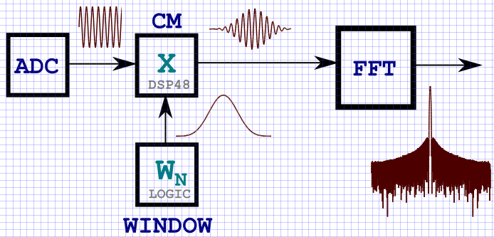
CDRD: a typical signal flow pattern through DSP nodes for spectrum analysis tasks.
Many people know from the “Digital Signal Processing” course that for an infinite time signal of a sinusoidal shape, its spectrum is a delta function at the signal frequency. In practice, the spectrum of a real time-limited harmonic signal is equivalent to the ~ sin (x) / x function , and the width of the main lobe depends on the duration of the signal analysis interval T. The time limit is nothing but multiplying a signal by a rectangular envelope. It is known from the DSP course that multiplication of signals in the time domain is a convolution of their spectra in the frequency domain (and vice versa), therefore the spectrum of the bounded rectangular envelope of the harmonic signal is equivalent to ~ sinc (x). This is also due to the fact that we cannot integrate the signal on an infinite time interval, and the Fourier transform in discrete form, expressed in a finite sum, is limited in the number of samples. As a rule, the FFT length in modern digital FPGA processing devices takes NFFT values from 8 to several million points. In other words, the spectrum of the input signal is calculated on the interval T , which in many cases is equal to NFFT. By limiting the signal on the interval T , we thereby impose a "window" of a rectangular shape, the duration of T samples. Therefore, the resulting spectrum is the spectrum of a multiplied harmonic signal and a rectangular envelope. In DSP tasks, windows of various shapes have been invented for quite a long time, which, when applied to a signal in the time domain, can improve its spectral characteristics. A large number of various windows is primarily due to one of the main features of any window overlay. This feature is expressed in the relationship between the level of side lobes and the width of the central lobe. Known pattern: the stronger the suppression of side lobes, the wider the main lobe, and vice versa.
One of the applications of window functions: the detection of weak signals against the background of stronger by suppressing the level of side lobes. The main window functions in DSP tasks are triangular, sinusoidal, Lanczos window, Hannah, Hamming, Blackman, Harris, Blackman-Harris, flat top window, Natall, Gauss, Kaiser window and many others. Most of them are expressed in a finite series by summing up the harmonic signals with specific weighting factors. Windows of complex shape are calculated by taking an exponent (Gauss window) or a modified Bessel function (Kaiser window), and will not be considered in this article. More information about window functions can be found in the literature, which I traditionally give at the end of the article.
The following figure shows typical window functions and their spectral characteristics constructed using Matlab CAD tools.

At the beginning of the article I inserted the KDPV, which shows in general form a block diagram of the multiplication of the input data by the window function. Obviously, the easiest way to implement storing a window function in an FPGA is to write it into memory (block RAMB or distributed Distributed - not a big deal), and then cyclically retrieve the data at the time of receipt of the input signal samples. As a rule, in modern FPGAs the volumes of internal memory allow storing window functions of relatively small size, which are then multiplied with the incoming input signals. By small, I mean window functions with a length of up to 64K samples.
But what if the length of the window function is too large? For example, 1M readings. It is easy to calculate that for such a window function, represented in a 32-bit bit grid, you will need NRAMB = 1024 * 1024 * 32/32768 = 1024 cells of the RAMB36K type of FPGA Xilinx crystals. And for 16M counts? 16 thousand memory cells! In one modern FPGA there is simply no such memory. For many FPGAs this is too much, but in other cases it is a wasteful use of FPGA resources (and, of course, the customer’s cash).
In this regard, you need to come up with a method for generating samples of the window function directly in the FPGA on the fly, without recording the coefficients from the remote device into the block memory. Fortunately, the basic things have long been invented for us. Using an algorithm like CORDIC (method "figure by digit ") manages to design a lot of window functions, the formulas of which are expressed through harmonic signals (Blackman-Harris, Hannah, Hamming, Nattala, etc.)
CORDIC is a simple and convenient iterative method for calculating the rotation of the coordinate system, which allows to calculate complex functions by performing primitive addition and shift operations. Using the CORDIC algorithm, it is possible to calculate the sin (x), cos (x) harmonic signals, find the atan (x) and atan2 (x, y) phase, hyperbolic trigonometric functions, rotate the vector, extract the number root, etc.
At first, I wanted to take a ready-made CORDIC core and reduce the amount of work, but I have a long-time dislike for Xilinx cores. After studying the repositories on the githaba, I realized that all the kernels represented are not suitable for a number of reasons (poorly documented and unreadable, not universal, made for a specific task or element base,written in verilog , etc.). Then i asked comrade lazifodo this job for me. Of course, he coped with it, because the implementation of CORDIC is one of the simplest tasks in the field of DSP. But since I'm impatient, in parallel with his work, I wrote my own bike with my parameterized kernel. The main features are a configurable bitness of the output signals DATA_WIDTH and the input normalized phase PHASE_WIDTH from -1 to 1, the task of the calculation accuracy is PRECISION. The CORDIC core is made along a conveyor parallel circuit — at each clock cycle the core is ready to perform calculations and receive input samples. The kernel spends on computing the output sample of N clock cycles, the number of which depends on the bitness of the output samples (the greater the bit depth - the more iterations to calculate the output value). All calculations occur in parallel. Thus, CORDIC is the base kernel for creating window functions.
In this article, I implement only those window functions that are expressed through harmonic signals (Hannah, Hamming, Blackman-Harris of a different order, etc.). What is needed for this? In general terms, the formula for constructing a window looks like a series of finite length.

A specific set of coefficients a k and row members determines the name of the window. The most popular and frequently used is the Blackman-Harris window: of a different order (from 3 to 11). Below is a table of coefficients for Blackman-Harris windows:

In principle, the Blackman-Harris window set is applicable in many spectral analysis problems, and there is no need to try to use complex Gauss or Kaiser windows. The Nattala or flat top windows are just a variation of windows with different weights, but with the same basic principles as Blackman-Harris. It is known that the more members of the series - the stronger the suppression of the side-lobe level (provided that the window capacity of the window function is reasonably chosen). Based on the task, the developer is simply to choose the type of windows used.
All the cores of window functions are designed using the classical approach of describing digital circuits on the FPGA and written in the VHDL language. Below is a list of components made:
The source code for the Blackman-Harris window component is 3 orders of magnitude:
In some cases, I used the UNISIM library to embed the DSP48E1 and DSP48E2 nodes in the project, which ultimately allows us to increase the computation speed due to pipelining inside these blocks, but as practice has shown, it is faster and easier to give up laziness and write something like P = A * B + C and specify the following directives in the code:
It works fine and hard for the synthesizer sets the type of element on which the mathematical function is implemented.
In addition, I implemented all the kernels using the Vivado HLS tools . I will list the main advantages of Vivado HLS - a high speed of design ( time-to-market ) in high-level C or C ++ languages, fast modeling of the developed nodes due to the lack of the concept of clock frequency, flexible configuration of solutions (in terms of resources and performance) by introducing pragmas and directives in the project, as well as a low entry threshold for developers in high-level languages. The main disadvantage is the non-optimal cost of FPGA resources in comparison with the classical approach. Also, it is not possible to achieve the speeds of work that are provided by the classic old RTL methods (VHDL, Verilog, SV). Well, the biggest drawback- this is a dance with a tambourine, but this is characteristic of the entire CAD system from Xilinx. (Note: in the Vivado HLS debugger and in the real C ++ model, different results are often obtained, since the Vivado HLS works crookedly when using the advantages of arbitrary precision ).
The following picture shows the log of the synthesized CORDIC core in Vivado HLS. It is quite informative and displays a lot of useful information: the number of resources used, the user interface of the kernel, cycles and their properties, the delay for calculations, the interval for calculating the output value (important when designing sequential and parallel circuits):

You can also see the way to calculate data in various components (functions). It can be seen that the phase data is read at the zero cycle, and at 7 and 8 clock cycles the result of the CORDIC node is displayed.

The result of Vivado HLS: a synthesized RTL core created from C-code. The log shows that, according to the time analysis, the kernel successfully passes all the restrictions:

Another big plus of Vivado HLS is that it makes a testbench of synthesized RTL code based on the model used to check the C-code to check the result. This may be a primitive check, but I think that this is very cool and quite convenient enough to compare the work of the algorithm in C and HDL. Below is a screenshot from Vivado, showing a simulation of the kernel model of a window function obtained by means of Vivado HLS:

Thus, for all window functions, similar results were obtained, regardless of the design method - on VHDL or on C ++. However, in the first case, greater work frequency and fewer resources are used, and in the second case, the maximum design speed is achieved. Both approaches have the right to life.
I specifically counted how much time I would spend on developing with different methods. I implemented the C ++ project in Vivado HLS ~ 12 times faster than on VHDL.
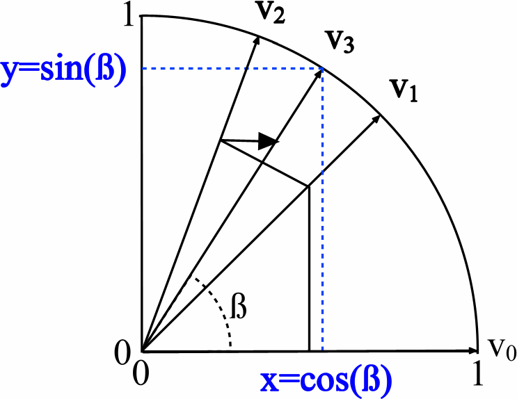
Compare the source code in HDL and C ++ for the core CORDIC. The algorithm, as mentioned earlier, is based on the operations of addition, subtraction and shift. On VHDL, it looks like this: there are three data vectors - one is responsible for the angle rotation, and the other two determine the length of the vector along the X and Y axes, which is equivalent to sin and cos (see the picture from the wiki):
By iteratively calculating the Z value, in parallel X and Y values are calculated. The process of cyclic search for output values on HDL:
In C ++, the Vivado HLS code looks almost the same, but the record is several times shorter:
Apparently, the same cycle with shift and additions is used. However, by default, all loops in Vivado HLS are “minimized” and are executed sequentially, as planned for the C ++ language. The introduction of the HLS UNROLL or HLS PIPELINE pragma converts sequential calculations to parallel ones. This leads to an increase in the resources of the FPGA, but it allows you to calculate and submit new values to the core at each clock cycle.
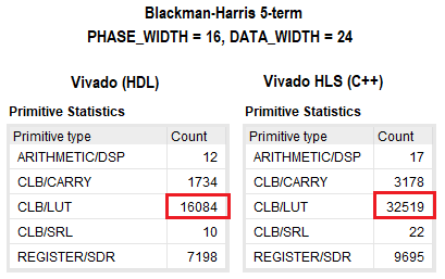
The results of the project synthesis on VHDL and C ++ are presented in the figure below. As can be seen, logically, the discrepancy is two times in favor of the traditional approach. For the remaining FPGA resources the difference is not significant. I did not really go into the optimization of the project in C ++, but definitely by setting different directives or partially changing the code, the amount of resources used can be reduced. In both cases, the timings converged for a given core frequency of ~ 350 MHz.
Since the calculations are performed in a fixed point format, the window functions have a number of features that must be considered when designing DSP systems on the FPGA. For example, the greater the data width of the window function - the better the overlap accuracy of the window. On the other hand, if the window function is insufficiently small, distortions will be introduced into the resulting waveform, which will affect the quality of the spectral characteristics. For example, a window function should have at least 20 bits when multiplied by a signal of 2 ^ 20 = 1M samples.
This article shows one of the ways to design window functions without using external memory or block FPGA memory. A method is provided to use only the logical resources of the FPGA (and in some cases, DSP blocks). Using the CORDIC algorithm, it is possible to obtain window functions of any bit depth (within reasonable limits), of any length and order, and therefore - to have a set of practically any spectral characteristics of the window.
In one of the works, I managed to get a stable operating Blackman-Harris window function 5 and 7 on 1M samples at a frequency of ~ 375 MHz, and also to make a generator of turning factors for a CORDIC based FFT at a frequency of ~ 400 MHz. Used FPGA crystal: Kintex Ultrascale + (xcku11p-ffva1156-2-e).
Link to github projecthere . The project contains a mathematical model in Matlab, source codes for window functions and CORDIC on VHDL, as well as models of listed window functions in C ++ for Vivado HLS.
I also advise a very popular book on DSP - E. Aificher, Jervis B. Digital Signal Processing. Practical approach
Thank you for your attention!
CDRD: a typical signal flow pattern through DSP nodes for spectrum analysis tasks.
Introduction
Many people know from the “Digital Signal Processing” course that for an infinite time signal of a sinusoidal shape, its spectrum is a delta function at the signal frequency. In practice, the spectrum of a real time-limited harmonic signal is equivalent to the ~ sin (x) / x function , and the width of the main lobe depends on the duration of the signal analysis interval T. The time limit is nothing but multiplying a signal by a rectangular envelope. It is known from the DSP course that multiplication of signals in the time domain is a convolution of their spectra in the frequency domain (and vice versa), therefore the spectrum of the bounded rectangular envelope of the harmonic signal is equivalent to ~ sinc (x). This is also due to the fact that we cannot integrate the signal on an infinite time interval, and the Fourier transform in discrete form, expressed in a finite sum, is limited in the number of samples. As a rule, the FFT length in modern digital FPGA processing devices takes NFFT values from 8 to several million points. In other words, the spectrum of the input signal is calculated on the interval T , which in many cases is equal to NFFT. By limiting the signal on the interval T , we thereby impose a "window" of a rectangular shape, the duration of T samples. Therefore, the resulting spectrum is the spectrum of a multiplied harmonic signal and a rectangular envelope. In DSP tasks, windows of various shapes have been invented for quite a long time, which, when applied to a signal in the time domain, can improve its spectral characteristics. A large number of various windows is primarily due to one of the main features of any window overlay. This feature is expressed in the relationship between the level of side lobes and the width of the central lobe. Known pattern: the stronger the suppression of side lobes, the wider the main lobe, and vice versa.
One of the applications of window functions: the detection of weak signals against the background of stronger by suppressing the level of side lobes. The main window functions in DSP tasks are triangular, sinusoidal, Lanczos window, Hannah, Hamming, Blackman, Harris, Blackman-Harris, flat top window, Natall, Gauss, Kaiser window and many others. Most of them are expressed in a finite series by summing up the harmonic signals with specific weighting factors. Windows of complex shape are calculated by taking an exponent (Gauss window) or a modified Bessel function (Kaiser window), and will not be considered in this article. More information about window functions can be found in the literature, which I traditionally give at the end of the article.
The following figure shows typical window functions and their spectral characteristics constructed using Matlab CAD tools.
Implementation
At the beginning of the article I inserted the KDPV, which shows in general form a block diagram of the multiplication of the input data by the window function. Obviously, the easiest way to implement storing a window function in an FPGA is to write it into memory (block RAMB or distributed Distributed - not a big deal), and then cyclically retrieve the data at the time of receipt of the input signal samples. As a rule, in modern FPGAs the volumes of internal memory allow storing window functions of relatively small size, which are then multiplied with the incoming input signals. By small, I mean window functions with a length of up to 64K samples.
But what if the length of the window function is too large? For example, 1M readings. It is easy to calculate that for such a window function, represented in a 32-bit bit grid, you will need NRAMB = 1024 * 1024 * 32/32768 = 1024 cells of the RAMB36K type of FPGA Xilinx crystals. And for 16M counts? 16 thousand memory cells! In one modern FPGA there is simply no such memory. For many FPGAs this is too much, but in other cases it is a wasteful use of FPGA resources (and, of course, the customer’s cash).
In this regard, you need to come up with a method for generating samples of the window function directly in the FPGA on the fly, without recording the coefficients from the remote device into the block memory. Fortunately, the basic things have long been invented for us. Using an algorithm like CORDIC (method "figure by digit ") manages to design a lot of window functions, the formulas of which are expressed through harmonic signals (Blackman-Harris, Hannah, Hamming, Nattala, etc.)
CORDIC
CORDIC is a simple and convenient iterative method for calculating the rotation of the coordinate system, which allows to calculate complex functions by performing primitive addition and shift operations. Using the CORDIC algorithm, it is possible to calculate the sin (x), cos (x) harmonic signals, find the atan (x) and atan2 (x, y) phase, hyperbolic trigonometric functions, rotate the vector, extract the number root, etc.
At first, I wanted to take a ready-made CORDIC core and reduce the amount of work, but I have a long-time dislike for Xilinx cores. After studying the repositories on the githaba, I realized that all the kernels represented are not suitable for a number of reasons (poorly documented and unreadable, not universal, made for a specific task or element base,
Window functions
In this article, I implement only those window functions that are expressed through harmonic signals (Hannah, Hamming, Blackman-Harris of a different order, etc.). What is needed for this? In general terms, the formula for constructing a window looks like a series of finite length.
A specific set of coefficients a k and row members determines the name of the window. The most popular and frequently used is the Blackman-Harris window: of a different order (from 3 to 11). Below is a table of coefficients for Blackman-Harris windows:
In principle, the Blackman-Harris window set is applicable in many spectral analysis problems, and there is no need to try to use complex Gauss or Kaiser windows. The Nattala or flat top windows are just a variation of windows with different weights, but with the same basic principles as Blackman-Harris. It is known that the more members of the series - the stronger the suppression of the side-lobe level (provided that the window capacity of the window function is reasonably chosen). Based on the task, the developer is simply to choose the type of windows used.
FPGA implementation - traditional approach
All the cores of window functions are designed using the classical approach of describing digital circuits on the FPGA and written in the VHDL language. Below is a list of components made:
- bh_win_7term - Blackman-Harris 7th order, a window with maximum suppression of side flakes.
- bh_win_5term - Blackman-Harris 5 order, includes a window with a flat top.
- bh_win_4term - Blackman-Harris 4 order, includes the window Nattala and Blackman-Nattala.
- bh_win_3term - Blackman-Harris 3 orders,
- hamming_win - Hamming and Hanna windows.
The source code for the Blackman-Harris window component is 3 orders of magnitude:
entity bh_win_3term isgeneric (
		TD          : time:=0.5ns;      --! Time delay
		PHI_WIDTH   : integer:=10;      --! Signal period = 2^PHI_WIDTH
		DAT_WIDTH   : integer:=16;      --! Output data width
        XSERIES     : string:="ULTRA"--! for 6/7 series: "7SERIES"; for ULTRASCALE: "ULTRA";
	);
	port (
		RESET       : instd_logic; --! Global reset
		CLK         : instd_logic; --! System clock
		AA0         : instd_logic_vector(DAT_WIDTH-1downto0); -- A0
		AA1         : instd_logic_vector(DAT_WIDTH-1downto0); -- A1
		AA2         : instd_logic_vector(DAT_WIDTH-1downto0); -- A2
		ENABLE      : instd_logic; --! Clock enable
		DT_WIN      : outstd_logic_vector(DAT_WIDTH-1downto0); --! Output
		DT_VLD      : outstd_logic--! Output data valid
	);
end bh_win_3term;
In some cases, I used the UNISIM library to embed the DSP48E1 and DSP48E2 nodes in the project, which ultimately allows us to increase the computation speed due to pipelining inside these blocks, but as practice has shown, it is faster and easier to give up laziness and write something like P = A * B + C and specify the following directives in the code:
attribute USE_DSP of <signal_name>: signalis"YES";It works fine and hard for the synthesizer sets the type of element on which the mathematical function is implemented.
Vivado hls
In addition, I implemented all the kernels using the Vivado HLS tools . I will list the main advantages of Vivado HLS - a high speed of design ( time-to-market ) in high-level C or C ++ languages, fast modeling of the developed nodes due to the lack of the concept of clock frequency, flexible configuration of solutions (in terms of resources and performance) by introducing pragmas and directives in the project, as well as a low entry threshold for developers in high-level languages. The main disadvantage is the non-optimal cost of FPGA resources in comparison with the classical approach. Also, it is not possible to achieve the speeds of work that are provided by the classic old RTL methods (VHDL, Verilog, SV). Well, the biggest drawback- this is a dance with a tambourine, but this is characteristic of the entire CAD system from Xilinx. (Note: in the Vivado HLS debugger and in the real C ++ model, different results are often obtained, since the Vivado HLS works crookedly when using the advantages of arbitrary precision ).
The following picture shows the log of the synthesized CORDIC core in Vivado HLS. It is quite informative and displays a lot of useful information: the number of resources used, the user interface of the kernel, cycles and their properties, the delay for calculations, the interval for calculating the output value (important when designing sequential and parallel circuits):
You can also see the way to calculate data in various components (functions). It can be seen that the phase data is read at the zero cycle, and at 7 and 8 clock cycles the result of the CORDIC node is displayed.
The result of Vivado HLS: a synthesized RTL core created from C-code. The log shows that, according to the time analysis, the kernel successfully passes all the restrictions:
Another big plus of Vivado HLS is that it makes a testbench of synthesized RTL code based on the model used to check the C-code to check the result. This may be a primitive check, but I think that this is very cool and quite convenient enough to compare the work of the algorithm in C and HDL. Below is a screenshot from Vivado, showing a simulation of the kernel model of a window function obtained by means of Vivado HLS:
Thus, for all window functions, similar results were obtained, regardless of the design method - on VHDL or on C ++. However, in the first case, greater work frequency and fewer resources are used, and in the second case, the maximum design speed is achieved. Both approaches have the right to life.
I specifically counted how much time I would spend on developing with different methods. I implemented the C ++ project in Vivado HLS ~ 12 times faster than on VHDL.
Comparison of approaches
Compare the source code in HDL and C ++ for the core CORDIC. The algorithm, as mentioned earlier, is based on the operations of addition, subtraction and shift. On VHDL, it looks like this: there are three data vectors - one is responsible for the angle rotation, and the other two determine the length of the vector along the X and Y axes, which is equivalent to sin and cos (see the picture from the wiki):
By iteratively calculating the Z value, in parallel X and Y values are calculated. The process of cyclic search for output values on HDL:
constant ROM_LUT : rom_array := (
    x"400000000000", x"25C80A3B3BE6", x"13F670B6BDC7", x"0A2223A83BBB",
    x"05161A861CB1", x"028BAFC2B209", x"0145EC3CB850", x"00A2F8AA23A9",
    x"00517CA68DA2", x"0028BE5D7661", x"00145F300123", x"000A2F982950",
    x"000517CC19C0", x"00028BE60D83", x"000145F306D6", x"0000A2F9836D",
    x"0000517CC1B7", x"000028BE60DC", x"0000145F306E", x"00000A2F9837",
    x"00000517CC1B", x"0000028BE60E", x"00000145F307", x"000000A2F983",
    x"000000517CC2", x"00000028BE61", x"000000145F30", x"0000000A2F98",
    x"0000000517CC", x"000000028BE6", x"0000000145F3", x"00000000A2FA",
    x"00000000517D", x"0000000028BE", x"00000000145F", x"000000000A30",
    x"000000000518", x"00000000028C", x"000000000146", x"0000000000A3",
    x"000000000051", x"000000000029", x"000000000014", x"00000000000A",
    x"000000000005", x"000000000003", x"000000000001", x"000000000000"
);
pr_crd: process(clk, reset)
beginif (reset = '1') then---- Reset sine / cosine / angle vector ----
		sigX <= (others => (others => '0'));
		sigY <= (others => (others => '0'));
		sigZ <= (others => (others => '0'));
    elsif rising_edge(clk) then
		sigX(0) <= init_x;
		sigY(0) <= init_y;
		sigZ(0) <= init_z;
		---- calculate sine & cosine ----
        lpXY: for ii in0to DATA_WIDTH-2loopif (sigZ(ii)(sigZ(ii)'left) = '1') then
                sigX(ii+1) <= sigX(ii) + sigY(ii)(DATA_WIDTH+PRECISION-1downto ii);
                sigY(ii+1) <= sigY(ii) - sigX(ii)(DATA_WIDTH+PRECISION-1downto ii);
            else
                sigX(ii+1) <= sigX(ii) - sigY(ii)(DATA_WIDTH+PRECISION-1downto ii);
                sigY(ii+1) <= sigY(ii) + sigX(ii)(DATA_WIDTH+PRECISION-1downto ii);
            endif;
        endloop;
		---- calculate phase ----
        lpZ: for ii in0to DATA_WIDTH-2loopif (sigZ(ii)(sigZ(ii)'left) = '1') then
                sigZ(ii+1) <= sigZ(ii) + ROM_TABLE(ii);
            else
                sigZ(ii+1) <= sigZ(ii) - ROM_TABLE(ii);
            endif;
        endloop;
    endif;
endprocess;
In C ++, the Vivado HLS code looks almost the same, but the record is several times shorter:
// Unrolled loop //int k;
stg: for (k = 0; k < NWIDTH; k++) {
#pragma HLS UNROLLif (z[k] < 0) {
		x[k+1] = x[k] + (y[k] >> k);
		y[k+1] = y[k] - (x[k] >> k);
		z[k+1] = z[k] + lut_angle[k];
	} else {
		x[k+1] = x[k] - (y[k] >> k);
		y[k+1] = y[k] + (x[k] >> k);
		z[k+1] = z[k] - lut_angle[k];
	}
}
Apparently, the same cycle with shift and additions is used. However, by default, all loops in Vivado HLS are “minimized” and are executed sequentially, as planned for the C ++ language. The introduction of the HLS UNROLL or HLS PIPELINE pragma converts sequential calculations to parallel ones. This leads to an increase in the resources of the FPGA, but it allows you to calculate and submit new values to the core at each clock cycle.
The results of the project synthesis on VHDL and C ++ are presented in the figure below. As can be seen, logically, the discrepancy is two times in favor of the traditional approach. For the remaining FPGA resources the difference is not significant. I did not really go into the optimization of the project in C ++, but definitely by setting different directives or partially changing the code, the amount of resources used can be reduced. In both cases, the timings converged for a given core frequency of ~ 350 MHz.
Features of the implementation
Since the calculations are performed in a fixed point format, the window functions have a number of features that must be considered when designing DSP systems on the FPGA. For example, the greater the data width of the window function - the better the overlap accuracy of the window. On the other hand, if the window function is insufficiently small, distortions will be introduced into the resulting waveform, which will affect the quality of the spectral characteristics. For example, a window function should have at least 20 bits when multiplied by a signal of 2 ^ 20 = 1M samples.
Conclusion
This article shows one of the ways to design window functions without using external memory or block FPGA memory. A method is provided to use only the logical resources of the FPGA (and in some cases, DSP blocks). Using the CORDIC algorithm, it is possible to obtain window functions of any bit depth (within reasonable limits), of any length and order, and therefore - to have a set of practically any spectral characteristics of the window.
In one of the works, I managed to get a stable operating Blackman-Harris window function 5 and 7 on 1M samples at a frequency of ~ 375 MHz, and also to make a generator of turning factors for a CORDIC based FFT at a frequency of ~ 400 MHz. Used FPGA crystal: Kintex Ultrascale + (xcku11p-ffva1156-2-e).
Link to github projecthere . The project contains a mathematical model in Matlab, source codes for window functions and CORDIC on VHDL, as well as models of listed window functions in C ++ for Vivado HLS.
Useful articles
- DSPLib window functions
- Some DSPlib window functions
- Expanded article on window filtering wiki
- Wiki article about CORDIC
- Vivado HLS Userguide
- Article about spectral analysis on Habré
I also advise a very popular book on DSP - E. Aificher, Jervis B. Digital Signal Processing. Practical approach
Thank you for your attention!