 July 20, 2015 at 16:03
How Python and Jinja Can Make FPGA Developer's Life Easier
Hello!
It so happens that the programming languages used impose a restriction on what we want to do, causing inconvenience in the development. What do developers do with this? Either resign themselves, or somehow try to get out of the situation.
One option is to use code auto-generation.
In this article I will tell:
If interested, welcome to kat!
We presume that you are developing in the Verilog-2001 language and you need to make a simple multiplexer:
Nothing complicated here.
However, if you are developing some kind of switch for 24/48 ports, then at some point you will need a module where packet switching will take place (this will require multiport multiplexers).
To do manually:
not very correct. In real life, you need a multiplexer, not just data, but specialized interfaces, where there will be not one, but several signals for each of the data streams (read, ports).
The soul asks to write something like this:
However, the use of arrays in the module ports is not permitted by the IEEE 1364-2001 standard (where Verilog-2001 is described).
So, for example, Quartus will produce this error: What to do?
One of the possible workarounds is considered at StackOverflow . The idea is working, but the article is not about that :)
Of course, you can give up and make the necessary wires with pens, but it is better that the machine does this for us: we
use the Template class from the Jinja2 template engine
We made a module template, where using for we described what we needed to duplicate, and then pulled render , passing the necessary parameters (number of ports, module name, etc.). These parameters using {{}} can be used in the template, providing the insertion of variables in the desired location.
The output was such a wonderful module:
The beauty lies in the fact that variables can be passed not just numbers or strings, but also Python types (sheets, dictionaries, objects of their classes), and then access the template in the same way as in Python code. For example, a call to a dictionary element would look like this:
Of course, this is a simple example, and most likely it could be done using perl / sed / awk, etc.
When I read about Jinja and played around with a simple example, I wondered if it could be used for more serious things. I remembered one problem that arises in FPGA development, which seems to be well automated. In order to smoothly bring you to this task, I will tell you a bit about what development consists of.
It is believed that the basis of rapid development for ASIC / FPGA is the use of ready-made code, designed as IP-cores. Without going into details, we can assume that the IP core is a library.
The idea is that all the firmware is split into IP cores that are written by yourself or bought,stolen / cracked , and then connected using standard interfaces (such as AXI or Avalon). The connection can take place either with handles or with the help of GUI applications, where you can click and connect the necessary kernels with the mouse. For example, Qsys , which comes with Quartus .
The advantages of this approach are obvious:
One of the minuses is the fact that there is an overhead for connecting via standard interfaces: it can take up more code or more resources (cells).
Each core has a set of CSR status registers .
Most often they are grouped according to words (for example, 32-bit), where inside they are divided by fields, which can have different operating modes:
Within the same register there can be several fields, and their modes of operation can be different.
Various chips also have CSR, from simple I2C expanders to transceivers, and even network cards.
What does top-level programmers look like?
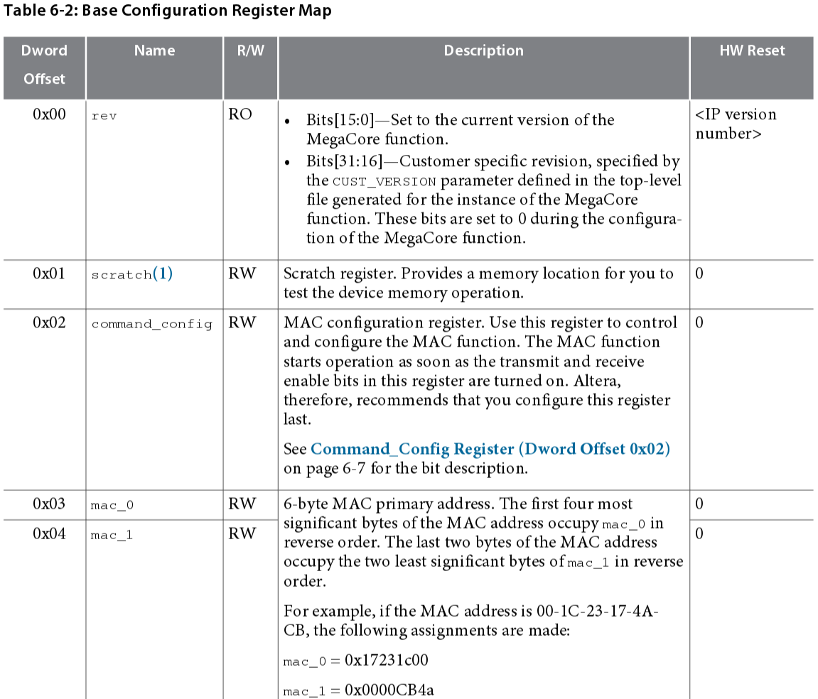
Consider the Altera Triple Speed Ethernet MAC Controller . If we open the documentation and go to the chapter Configuration Register Space , we will see the lists of all the registers through which you can both control the kernel and receive information about its state (for example, counters of received / sent packets).
I will give part of the table where the registers are described:
By the way, it is possible that the packets that make you read these lines went through this IP core.
For example, the registers 0x03 and 0x04 in this kernel are responsible for setting the MAC address. For a kernel (from Xilinx or Intel), these may be different registers.
This is how the change of MAC address in the driver looks like :
mac_addr_0 and mac_addr_1 are just our 0x03 and 0x04, which are very tricky (in my subjective opinion, although I assume that this is normal in drivers) are defined in the neighboring header file .
The developers of the IP core provide a document that describes all the CSRs, as well as what, how and in what order to configure. This documentation is passed to high-level programmers, they in turn write functions similar to tse_update_mac_addr and make it all work :)
Often, the task posed by one core cannot be solved - there are several of them in the system.
Control interfaces can be hung on one bus, allocating each of the cores with its own address space:
If the upper level needs to be written in kernel register B in 0x03, then it must conduct a transaction at address 0x0103. (To simplify, we believe that the addresses are not byte, but according to the words. In real life, it may turn out that you need to write by byte addresses, and then our request for a 32-bit register will be a transaction at 0x010C).

A master (it can be a CPU (ARM / x86) or an MCU, or some other IP core in general) through a management interface, performs a read or write transaction. Very often, IP core management interfaces are done according to one of the standards (AXI or Avalon).
If there are several slaves, then an interconnect module appears (multiplexer or bus arbiter). Its task is to accept requests from the master and see where to send this request, in the same way it can hold the bus while the slave is responding, etc. So, before this module, the request address was 0x0103, and after - 0x0003, because The IP core does not know (and should not) what address space is assigned to it.
Inside the IP core there should be a module that contains all these registers and converts them into a set of signals for controlling modules that are inside the IP core but hidden from the outside world.
In order not to speak on your fingers, consider a very simple abstract IP core of an Ethernet packet generator, which can be used, for example, in measuring equipment .
Let this kernel have these registers:
The IP core itself will look something like this:
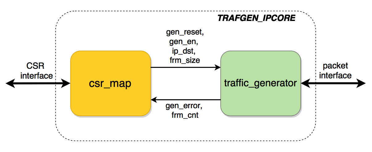
The csr_map module serves to “translate” the standard interface into a set of control signals for the traffic_generator module , which performs the core function of the kernel. Of course, rarely the IP core consists of only two modules: most likely, control signals will be distributed to several modules inside the IP core.
I hope you guessed what I'm getting at: is
it possible to generate this csr_map automatically from some description of these registers ?
In real life, there can be about a hundred registers, and if this is automated, then:
We make two primitive classes for storing information by registers, and by bits (fields).
Using these classes, create a CSR description:
The template itself looks like this:
We pull the template generation:
We got such a module:
As you can see, the idea worked: from a simple text description a full-fledged module appeared, which does not need to be finished with your hands - you can immediately take it into production)
The similarity of Avalon-MM was used as a control interface .
With Jinja2 I met just a couple of days ago, when he looked at githabe implementation of 1G and 10G MAC-cores with the UDP / IP stack. By the way, it was written well, but I looked pretty superficially and in the simulation, and even more so on the hardware did not try.
The author uses Jinja2 to generate various modules, for example, the N-port multiplexer AXI4-Stream . This multiplexer is much trickier than the one I wrote at the beginning of the article.
Script to generate csr_mapI threw it in a hurry to feel the capabilities of Jinja2 (I'm sure I appreciated a small part of it), but I can recommend that all colleagues who are developing for FPGA play with this library, maybe you can speed up your development due to code auto-generation.
Of course, this script is raw, and we have not used it in development yet (and I don’t even know if we will use it or not, because for various reasons the beautiful architecture of IP cores sometimes remains just beautiful architecture).
Fully posted the source code on github . If this template is useful to someone, I’ll be glad: I’m ready to improve it upon requests, or accept someone’s pull-requests)
Thank you for your attention! If you have questions, ask without a doubt.
It so happens that the programming languages used impose a restriction on what we want to do, causing inconvenience in the development. What do developers do with this? Either resign themselves, or somehow try to get out of the situation.
One option is to use code auto-generation.
In this article I will tell:
- how to get around one of the limitations of the Verilog language used in developing ASIC / FPGA using code auto-generation using Python and the Jinja library .
- how to accelerate the development of IP cores by generating a module of control and status registers from their description.
If interested, welcome to kat!
Parameterization of modules
We presume that you are developing in the Verilog-2001 language and you need to make a simple multiplexer:
module simple_mux #(
  parameter D_WIDTH = 8
) (
  input  [D_WIDTH-1:0] data_0_i,
  input  [D_WIDTH-1:0] data_1_i,
  input                sel_i,
  output [D_WIDTH-1:0] data_o
);
assign data_o = ( sel_i ) ? ( data_1_i ):
                            ( data_0_i );
endmodule
Nothing complicated here.
However, if you are developing some kind of switch for 24/48 ports, then at some point you will need a module where packet switching will take place (this will require multiport multiplexers).
To do manually:
input [D_WIDTH-1:0] data_0_i,
input [D_WIDTH-1:0] data_1_i,
...
input [D_WIDTH-1:0] data_47_i,
not very correct. In real life, you need a multiplexer, not just data, but specialized interfaces, where there will be not one, but several signals for each of the data streams (read, ports).
The soul asks to write something like this:
module simple_mux #(
  parameter D_WIDTH   = 8,
  parameter PORT_CNT  = 48,
  // internal param
  parameter SEL_WIDTH = $clog2( PORT_CNT )
) (
  input  [D_WIDTH-1:0]   data_i [PORT_CNT-1:0],
  input  [SEL_WIDTH-1:0] sel_i,
  output [D_WIDTH-1:0]   data_o
);
assign data_o = data_i[ sel_i ];
endmodule
However, the use of arrays in the module ports is not permitted by the IEEE 1364-2001 standard (where Verilog-2001 is described).
So, for example, Quartus will produce this error: What to do?
Error (10773): Verilog HDL error: declaring module ports or function arguments with unpacked array types requires SystemVerilog extensions
Hidden text
Use SystemVerilog.
Hidden text
:)
One of the possible workarounds is considered at StackOverflow . The idea is working, but the article is not about that :)
Of course, you can give up and make the necessary wires with pens, but it is better that the machine does this for us: we
use the Template class from the Jinja2 template engine
  t = Template(u"""
module {{name}} #(
  parameter D_WIDTH = 8
) (
{%- for p in ports %}
  input  [D_WIDTH-1:0]       data_{{p}}_i,
{%- endfor %}
  input  [{{sel_width-1}}:0] sel_i,
  output [D_WIDTH-1:0]       data_o
);
always @(*)
  begin
    case( sel_i )
{% for p in ports %}
    {{sel_width}}'d{{p}}:
      begin
        data_o = data_{{p}}_i;
      end
{%  endfor %}
    endcase
  end
endmodule
""")
  print t.render(
       n         = 4,
       sel_width = 2,
       name      = "simple_mux_4habr",
       ports     = range( 4 )
  )
We made a module template, where using for we described what we needed to duplicate, and then pulled render , passing the necessary parameters (number of ports, module name, etc.). These parameters using {{}} can be used in the template, providing the insertion of variables in the desired location.
The output was such a wonderful module:
Hidden text
module simple_mux_4habr #(
  parameter D_WIDTH = 8
) (
  input  [D_WIDTH-1:0]       data_0_i,
  input  [D_WIDTH-1:0]       data_1_i,
  input  [D_WIDTH-1:0]       data_2_i,
  input  [D_WIDTH-1:0]       data_3_i,
  input  [1:0] sel_i,
  output [D_WIDTH-1:0]       data_o
);
always @(*)
  begin
    case( sel_i )
    2'd0:
      begin
        data_o = data_0_i;
      end
    2'd1:
      begin
        data_o = data_1_i;
      end
    2'd2:
      begin
        data_o = data_2_i;
      end
    2'd3:
      begin
        data_o = data_3_i;
      end
    endcase
  end
endmodule
The beauty lies in the fact that variables can be passed not just numbers or strings, but also Python types (sheets, dictionaries, objects of their classes), and then access the template in the same way as in Python code. For example, a call to a dictionary element would look like this:
{{ foo['bar'] }}
Of course, this is a simple example, and most likely it could be done using perl / sed / awk, etc.
When I read about Jinja and played around with a simple example, I wondered if it could be used for more serious things. I remembered one problem that arises in FPGA development, which seems to be well automated. In order to smoothly bring you to this task, I will tell you a bit about what development consists of.
IP cores
It is believed that the basis of rapid development for ASIC / FPGA is the use of ready-made code, designed as IP-cores. Without going into details, we can assume that the IP core is a library.
The idea is that all the firmware is split into IP cores that are written by yourself or bought,
The advantages of this approach are obvious:
- ready code revision
- separate core testing
- standardization of data exchange between modules
One of the minuses is the fact that there is an overhead for connecting via standard interfaces: it can take up more code or more resources (cells).
Each core has a set of CSR status registers .
Most often they are grouped according to words (for example, 32-bit), where inside they are divided by fields, which can have different operating modes:
- RW - read and write: you can write and read. Serve to configure the kernel (for example, the inclusion of a particular operating mode, setting some parameters, etc.).
- RW / SC - read write self clear: if you write a unit, it itself will reset to zero (it may be convenient for resetting the kernel or kernel module: you put the unit, and it will reset itself to zero).
- RO - read only: read only (e.g. for statistics or kernel status). Also, some registers are made by RO to store constant values (for example, the kernel version, or its capabilities).
- RO / LL and RO / LH - read only latch low / latch high: another tricky register - can be used to track crashes, for example, a file overflow occurred (the full signal became equal to one), if you just put it on an RO register, The CPU that reads these registers can skip this event, because this can happen in just a few measures. But if you do LH, then as soon as there is a unit, it clicks and waits for the next reading. If this register was read, then the register value will automatically be reset to zero.
Within the same register there can be several fields, and their modes of operation can be different.
Various chips also have CSR, from simple I2C expanders to transceivers, and even network cards.
What does top-level programmers look like?
Consider the Altera Triple Speed Ethernet MAC Controller . If we open the documentation and go to the chapter Configuration Register Space , we will see the lists of all the registers through which you can both control the kernel and receive information about its state (for example, counters of received / sent packets).
I will give part of the table where the registers are described:
By the way, it is possible that the packets that make you read these lines went through this IP core.
For example, the registers 0x03 and 0x04 in this kernel are responsible for setting the MAC address. For a kernel (from Xilinx or Intel), these may be different registers.
This is how the change of MAC address in the driver looks like :
static void tse_update_mac_addr(struct altera_tse_private *priv, u8 *addr)
{
    u32 msb;
    u32 lsb;
    msb = (addr[3] << 24) | (addr[2] << 16) | (addr[1] << 8) | addr[0];
    lsb = ((addr[5] << 8) | addr[4]) & 0xffff;
    /* Set primary MAC address */
    csrwr32(msb, priv->mac_dev, tse_csroffs(mac_addr_0));
    csrwr32(lsb, priv->mac_dev, tse_csroffs(mac_addr_1));
}
mac_addr_0 and mac_addr_1 are just our 0x03 and 0x04, which are very tricky (in my subjective opinion, although I assume that this is normal in drivers) are defined in the neighboring header file .
The developers of the IP core provide a document that describes all the CSRs, as well as what, how and in what order to configure. This documentation is passed to high-level programmers, they in turn write functions similar to tse_update_mac_addr and make it all work :)
Multi-core systems
Often, the task posed by one core cannot be solved - there are several of them in the system.
Control interfaces can be hung on one bus, allocating each of the cores with its own address space:
- IP Core A: 0x0000 - 0x00FF
- IP Core B: 0x0100 - 0x01FF
- IP Core C: 0x0200 - 0x02FF
If the upper level needs to be written in kernel register B in 0x03, then it must conduct a transaction at address 0x0103. (To simplify, we believe that the addresses are not byte, but according to the words. In real life, it may turn out that you need to write by byte addresses, and then our request for a 32-bit register will be a transaction at 0x010C).
A master (it can be a CPU (ARM / x86) or an MCU, or some other IP core in general) through a management interface, performs a read or write transaction. Very often, IP core management interfaces are done according to one of the standards (AXI or Avalon).
If there are several slaves, then an interconnect module appears (multiplexer or bus arbiter). Its task is to accept requests from the master and see where to send this request, in the same way it can hold the bus while the slave is responding, etc. So, before this module, the request address was 0x0103, and after - 0x0003, because The IP core does not know (and should not) what address space is assigned to it.
We disassemble a specific IP core (we denote the problem)
Inside the IP core there should be a module that contains all these registers and converts them into a set of signals for controlling modules that are inside the IP core but hidden from the outside world.
In order not to speak on your fingers, consider a very simple abstract IP core of an Ethernet packet generator, which can be used, for example, in measuring equipment .
Let this kernel have these registers:
0x0:
[7:0]   - IP_CORE_VERSION [RO] - Версия IP-ядра
[15:8]  - Reserved
[16]    - GEN_EN [RW] - Разрешение генерации
[17]    - GEN_ERROR [ROLH] - Произошла ошибка при генерации
[30:18] - Reserved
[31]    - GEN_RESET [RWSC] - Сброс генератора
0x1:
[31:0]  - IP_DST [RW] - IP-адрес получателя пакетов
0x2:
[15:0]  - FRM_SIZE [RW] - Размер пакета
[31:16] - Reserved
0x3:
[31:0]  - FRM_CNT [RO] - Количество сгенерированных пакетов
The IP core itself will look something like this:
The csr_map module serves to “translate” the standard interface into a set of control signals for the traffic_generator module , which performs the core function of the kernel. Of course, rarely the IP core consists of only two modules: most likely, control signals will be distributed to several modules inside the IP core.
I hope you guessed what I'm getting at: is
it possible to generate this csr_map automatically from some description of these registers ?
In real life, there can be about a hundred registers, and if this is automated, then:
- You can avoid mistakes and uninteresting work.
- if you pay for lines of code, then get a bonus from the management (auto-generated code often takes a lot of lines).
- Spent time to spend reading the Habr (well, or giktaymsa, because FPGA hub moved there> _ <) or a game of kicker.
Solve the problem
We make two primitive classes for storing information by registers, and by bits (fields).
class Reg( ):
  def __init__( self, num, name ):
    self.num          = '{:X}'.format( num )
    self.name         = name
    self.name_lowcase = self.name.lower()
    self.bits         = []
  def add_bits( self, reg_bits ):
    self.bits.append( reg_bits )
class RegBits( ):
  def __init__( self, bit_msb, bit_lsb, name, mode = "RW", init_value = 0 ):
    self.bit_msb      = bit_msb
    self.bit_lsb      = bit_lsb
    self.width        = bit_msb - bit_lsb + 1
    self.name         = name
    self.name_lowcase = self.name.lower()
    self.mode         = mode
    self.init_value   = '{:X}'.format( init_value )
    # bit modes:
    # RO       - read only
    # RO_CONST - read only, constant value
    # RO_LH    - read only, latch high
    # RO_LL    - read only, latch low
    # RW       - read and write
    # RW_SC    - read and write, self clear
    assert self.mode in ["RO", "RO_CONST", "RO_LH", "RO_LL", "RW", "RW_SC" ], "Unknown bit mode"
    if self.mode in ["RO_LH", "RO_LL", "RW_SC"]:
      assert self.width == 1, "Wrong width for this bit mod"
    self.port_signal_input  = self.mode in ["RO", "RO_LH", "RO_LL"]
    self.port_signal_output = self.mode in ["RW", "RW_SC"]
    self.need_port_signal   = self.port_signal_input or self.port_signal_output
Using these classes, create a CSR description:
  MODULE_NAME = "trafgen_map_4habr"
  r0 = Reg( 0x0, "MAIN")
  r0.add_bits( RegBits( 7, 0,   "IP_CORE_VERSION",  "RO_CONST", 0x7      ) )
  r0.add_bits( RegBits( 16, 16, "GEN_EN" ,   "RW"      ) )
  r0.add_bits( RegBits( 17, 17, "GEN_ERROR", "RO_LH" ) )
  r0.add_bits( RegBits( 31, 31, "GEN_RESET", "RW_SC" ) )
  r1 = Reg( 0x1, "IP_DST" )
  # let ip destination in reset will be 178.248.233.33 ( habrahabr.ru )
  r1.add_bits( RegBits( 31, 0, "IP_DST", "RW", 0xB2F8E921  ) )
  r2 = Reg( 0x2, "FRM_SIZE" )
  r2.add_bits( RegBits( 15, 0, "FRM_SIZE", "RW", 64  ) )
  r3 = Reg( 0x3, "FRM_CNT" )
  r3.add_bits( RegBits( 31, 0, "FRM_CNT", "RO" ) )
  reg_l = [r0, r1, r2, r3]
The template itself looks like this:
Hidden text
csr_map_template = Template(u"""
{%- macro reg_name( r ) -%}
reg_{{r.num}}_{{r.name_lowcase}}
{%- endmacro %}
{%- macro reg_name_bits( r, b ) -%}
reg_{{r.num}}_{{r.name_lowcase}}___{{b.name_lowcase}}
{%- endmacro %}
{%- macro bit_init_value( b ) -%}
{{b.width}}'h{{b.init_value}}
{%- endmacro %}
{%- macro signal( width ) -%}
[{{width-1}}:0]
{%- endmacro %}
{%- macro print_port_signal( dir, width, name, eol="," ) -%}
{{ "  %-12s %-10s %-10s" | format( dir,  signal( width ),  name+eol ) }}
{%- endmacro %}
{%- macro get_port_name( b ) -%}
{%- if b.port_signal_input -%}
{{b.name_lowcase}}_i
{%- else -%}
{{b.name_lowcase}}_o
{%- endif -%}
{%- endmacro -%}
// Generated using CSR map generator
// https://github.com/johan92/csr-map-generator
module {{module_name}}(
{%- for p in data %}
  // Register {{p.name}} signals
{%- for b in p.bits %}
  {%- if b.port_signal_input %}
{{print_port_signal( "input", b.width, get_port_name( b ) )}}
  {%- elif b.port_signal_output %}
{{print_port_signal( "output", b.width, get_port_name( b ) )}}
  {%- endif %}
{%- endfor %}
{% endfor %}
  // CSR interface
{{print_port_signal( "input",  1,       "reg_clk_i"          ) }}
{{print_port_signal( "input",  1,       "reg_rst_i"          ) }}
{{print_port_signal( "input",  reg_d_w, "reg_wr_data_i"      ) }}
{{print_port_signal( "input",  1,       "reg_wr_en_i"        ) }}
{{print_port_signal( "input",  1,       "reg_rd_en_i"        ) }}
{{print_port_signal( "input",  reg_a_w, "reg_addr_i"         ) }}
{{print_port_signal( "output", reg_d_w, "reg_rd_data_o", ""  ) }}
);
{%- for p in data %}
// ******************************************
//        Register {{p.name}}
// ******************************************
logic [{{reg_d_w-1}}:0] {{reg_name( p )}}_read;
{%- for b in p.bits %}
{%- if b.mode != "RO" %}
logic [{{b.width-1}}:0] {{reg_name_bits( p, b )}} = {{bit_init_value( b )}};
{%- endif %}
{%- endfor %}
{% for b in p.bits %}
{%- if b.port_signal_output %}
always_ff @( posedge reg_clk_i or posedge reg_rst_i )
  if( reg_rst_i )
    {{reg_name_bits( p, b )}} <= {{bit_init_value( b )}};
  else
    if( reg_wr_en_i && ( reg_addr_i == {{reg_a_w}}'h{{p.num}} ) )
      {{reg_name_bits( p, b )}} <= reg_wr_data_i[{{b.bit_msb}}:{{b.bit_lsb}}];
  {%-if b.mode == "RW_SC" %}
    else
      {{reg_name_bits( p, b )}} <= {{bit_init_value( b )}};
  {% endif %}
{%- endif %}
{%- if b.mode == "RO_LH" or b.mode == "RO_LL" %}
always_ff @( posedge reg_clk_i or posedge reg_rst_i )
  if( reg_rst_i )
    {{reg_name_bits( p, b )}} <= {{bit_init_value( b )}};
  else
    begin
      if( reg_rd_en_i && ( reg_addr_i == {{reg_a_w}}'h{{p.num}} ) )
        {{reg_name_bits( p, b )}} <= {{bit_init_value( b )}};
      {% if b.mode == "RO_LL" %}
      if( {{get_port_name( b )}} == 1'b0 )
        {{reg_name_bits( p, b )}} <= 1'b0;
      {%- elif b.mode == "RO_LH" %}
      if( {{get_port_name( b )}} == 1'b1 )
        {{reg_name_bits( p, b )}} <= 1'b1;
      {%- endif %}
    end
{% endif %}
{% endfor %}
// assigning to output
{%- for b in p.bits %}
{%- if b.port_signal_output %}
assign {{get_port_name( b )}} = {{reg_name_bits( p, b )}};
{%- endif %}
{%- endfor %}
{%- macro print_in_always_comb( r, b, _right_value ) -%}
{%- if b == "" -%}
{{ "  %s%-7s = %s;" | format( reg_name( r ) + "_read",  "",  _right_value ) }}
{%- else -%}
{{ "  %s%-7s = %s;" | format( reg_name( r ) + "_read", "["+b.bit_msb|string+":"+b.bit_lsb|string+"]" ,  _right_value ) }}
{%- endif -%}
{%- endmacro %}
// assigning to read data
always_comb
  begin
  {{print_in_always_comb( p, "", reg_d_w|string+"'h0" ) }}
{%- for b in p.bits %}
  {%- if b.mode == "RO" %}
  {{print_in_always_comb( p, b, get_port_name( b ) )}}
  {%- else %}
  {{print_in_always_comb( p, b, reg_name_bits( p, b ) )}}
  {%- endif %}
{%- endfor %}
  end
{%- endfor %}
// ******************************************
//      Reading stuff
// ******************************************
logic [{{reg_d_w-1}}:0] reg_rd_data = {{reg_d_w}}'h0;
always_ff @( posedge reg_clk_i or posedge reg_rst_i )
  if( reg_rst_i )
    reg_rd_data <= {{reg_d_w}}'h0;
  else
    if( reg_rd_en_i )
      begin
        case( reg_addr_i )
        {% for p in data %}
        {{reg_a_w}}'h{{p.num}}:
          begin
            reg_rd_data <= {{reg_name( p )}}_read;
          end
        {% endfor %}
        default:
          begin
            reg_rd_data <= {{reg_d_w}}'h0;
          end
        endcase
      end
assign reg_rd_data_o = reg_rd_data;
endmodule
""")
We pull the template generation:
  res = csr_map_template.render(
      module_name = MODULE_NAME,
      reg_d_w     = 32,
      reg_a_w     = 8,
      data        = reg_l
  )
We got such a module:
Hidden text
// Generated using CSR map generator
// https://github.com/johan92/csr-map-generator
module trafgen_map_4habr(
  // Register MAIN signals
  output       [0:0]      gen_en_o,
  input        [0:0]      gen_error_i,
  output       [0:0]      gen_reset_o,
  // Register IP_DST signals
  output       [31:0]     ip_dst_o,
  // Register FRM_SIZE signals
  output       [15:0]     frm_size_o,
  // Register FRM_CNT signals
  input        [31:0]     frm_cnt_i,
  // CSR interface
  input        [0:0]      reg_clk_i,
  input        [0:0]      reg_rst_i,
  input        [31:0]     reg_wr_data_i,
  input        [0:0]      reg_wr_en_i,
  input        [0:0]      reg_rd_en_i,
  input        [7:0]      reg_addr_i,
  output       [31:0]     reg_rd_data_o
);
// ******************************************
//        Register MAIN
// ******************************************
logic [31:0] reg_0_main_read;
logic [7:0] reg_0_main___ip_core_version = 8'h7;
logic [0:0] reg_0_main___gen_en = 1'h0;
logic [0:0] reg_0_main___gen_error = 1'h0;
logic [0:0] reg_0_main___gen_reset = 1'h0;
always_ff @( posedge reg_clk_i or posedge reg_rst_i )
  if( reg_rst_i )
    reg_0_main___gen_en <= 1'h0;
  else
    if( reg_wr_en_i && ( reg_addr_i == 8'h0 ) )
      reg_0_main___gen_en <= reg_wr_data_i[16:16];
always_ff @( posedge reg_clk_i or posedge reg_rst_i )
  if( reg_rst_i )
    reg_0_main___gen_error <= 1'h0;
  else
    begin
      if( reg_rd_en_i && ( reg_addr_i == 8'h0 ) )
        reg_0_main___gen_error <= 1'h0;
      if( gen_error_i == 1'b1 )
        reg_0_main___gen_error <= 1'b1;
    end
always_ff @( posedge reg_clk_i or posedge reg_rst_i )
  if( reg_rst_i )
    reg_0_main___gen_reset <= 1'h0;
  else
    if( reg_wr_en_i && ( reg_addr_i == 8'h0 ) )
      reg_0_main___gen_reset <= reg_wr_data_i[31:31];
    else
      reg_0_main___gen_reset <= 1'h0;
// assigning to output
assign gen_en_o = reg_0_main___gen_en;
assign gen_reset_o = reg_0_main___gen_reset;
// assigning to read data
always_comb
  begin
    reg_0_main_read        = 32'h0;
    reg_0_main_read[7:0]   = reg_0_main___ip_core_version;
    reg_0_main_read[16:16] = reg_0_main___gen_en;
    reg_0_main_read[17:17] = reg_0_main___gen_error;
    reg_0_main_read[31:31] = reg_0_main___gen_reset;
  end
// ******************************************
//        Register IP_DST
// ******************************************
logic [31:0] reg_1_ip_dst_read;
logic [31:0] reg_1_ip_dst___ip_dst = 32'hB2F8E921;
always_ff @( posedge reg_clk_i or posedge reg_rst_i )
  if( reg_rst_i )
    reg_1_ip_dst___ip_dst <= 32'hB2F8E921;
  else
    if( reg_wr_en_i && ( reg_addr_i == 8'h1 ) )
      reg_1_ip_dst___ip_dst <= reg_wr_data_i[31:0];
// assigning to output
assign ip_dst_o = reg_1_ip_dst___ip_dst;
// assigning to read data
always_comb
  begin
    reg_1_ip_dst_read        = 32'h0;
    reg_1_ip_dst_read[31:0]  = reg_1_ip_dst___ip_dst;
  end
// ******************************************
//        Register FRM_SIZE
// ******************************************
logic [31:0] reg_2_frm_size_read;
logic [15:0] reg_2_frm_size___frm_size = 16'h40;
always_ff @( posedge reg_clk_i or posedge reg_rst_i )
  if( reg_rst_i )
    reg_2_frm_size___frm_size <= 16'h40;
  else
    if( reg_wr_en_i && ( reg_addr_i == 8'h2 ) )
      reg_2_frm_size___frm_size <= reg_wr_data_i[15:0];
// assigning to output
assign frm_size_o = reg_2_frm_size___frm_size;
// assigning to read data
always_comb
  begin
    reg_2_frm_size_read        = 32'h0;
    reg_2_frm_size_read[15:0]  = reg_2_frm_size___frm_size;
  end
// ******************************************
//        Register FRM_CNT
// ******************************************
logic [31:0] reg_3_frm_cnt_read;
// assigning to output
// assigning to read data
always_comb
  begin
    reg_3_frm_cnt_read        = 32'h0;
    reg_3_frm_cnt_read[31:0]  = frm_cnt_i;
  end
// ******************************************
//      Reading stuff
// ******************************************
logic [31:0] reg_rd_data = 32'h0;
always_ff @( posedge reg_clk_i or posedge reg_rst_i )
  if( reg_rst_i )
    reg_rd_data <= 32'h0;
  else
    if( reg_rd_en_i )
      begin
        case( reg_addr_i )
        8'h0:
          begin
            reg_rd_data <= reg_0_main_read;
          end
        8'h1:
          begin
            reg_rd_data <= reg_1_ip_dst_read;
          end
        8'h2:
          begin
            reg_rd_data <= reg_2_frm_size_read;
          end
        8'h3:
          begin
            reg_rd_data <= reg_3_frm_cnt_read;
          end
        default:
          begin
            reg_rd_data <= 32'h0;
          end
        endcase
      end
assign reg_rd_data_o = reg_rd_data;
endmodule
As you can see, the idea worked: from a simple text description a full-fledged module appeared, which does not need to be finished with your hands - you can immediately take it into production)
The similarity of Avalon-MM was used as a control interface .
Summarizing
With Jinja2 I met just a couple of days ago, when he looked at githabe implementation of 1G and 10G MAC-cores with the UDP / IP stack. By the way, it was written well, but I looked pretty superficially and in the simulation, and even more so on the hardware did not try.
The author uses Jinja2 to generate various modules, for example, the N-port multiplexer AXI4-Stream . This multiplexer is much trickier than the one I wrote at the beginning of the article.
Script to generate csr_mapI threw it in a hurry to feel the capabilities of Jinja2 (I'm sure I appreciated a small part of it), but I can recommend that all colleagues who are developing for FPGA play with this library, maybe you can speed up your development due to code auto-generation.
Of course, this script is raw, and we have not used it in development yet (and I don’t even know if we will use it or not, because for various reasons the beautiful architecture of IP cores sometimes remains just beautiful architecture).
Fully posted the source code on github . If this template is useful to someone, I’ll be glad: I’m ready to improve it upon requests, or accept someone’s pull-requests)
Thank you for your attention! If you have questions, ask without a doubt.
Hidden text
It’s a pity, of course, that the FPGA hub was moved to the clock.









