Mikrotik VRF + NAT - Manage devices with the same IP addresses from one host
Recently, a friend asked for help with setting up Mikrotik. The request was not entirely simple. The idea was to simultaneously manage four devices with an unmanaged TCP / IP stack from the same host. All these devices had the same IP settings, and just the IP address and mask, neither the gateway nor DNS are specified. Strange, but, as it turned out, a very real situation. We will not go into details of the reasons for the impossibility of reconfiguring addressing on these devices, but simply take this fact as an axiom. The task is set as it is, and it must be solved.
So, the initial data:
1. Four devices with the same IP settings - 192.168.1.1/24; GW and DNS are not specified; these settings cannot be changed.
2. A PC from which you must simultaneously have access to all four devices, for example, on the WEB interface.
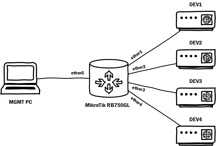
3. A simple MikroTik RB750GL for 5 ports.
MikroTik RB750GL with default settings uses 1 port for connecting to the Internet (NAT, FW), and the remaining ports for connecting to a local network with DHCP configured - like a regular home router or a Small Business series router. We need to use all 5 ports, so for starters we completely clean the config and get rid of NAT, FW and DHCP.
So, kofig cleared, collect the scheme:
Now to the point ...
The first and main problem that confronts us is the use of the same IP addresses or IP addresses from the same subnet on different router interfaces to ensure network accessibility of the target devices. How to interpret the basics of network interaction with one routing table, this is impossible. So we need to make several routing tables, and Virtual Routing and Forwarding (VRF) will help us with this. We will not dive into VRF very much - we just need to put different interfaces in different routing tables:
Excellent. Now configure the IP addressing according to the scheme: the

IP address 192.168.2.1 will be used to access the management of MikroTik itself:
Recall that the devices themselves that need to be controlled also lack the ability to configure a default gateway. We also need to somehow separate these devices for access from the MGMT PC. Naturally NAT. For each device, select IP from the 192.168.2.0/24 subnet and configure it on the ether5 interface:
We don’t touch NAT itself yet and remember that our packets should run between different routing tables. To do this, put the route labels according to the new IP addresses, which we will NAT later. According to the NetFilter documentation, the Mangle table, which is responsible for marking traffic, processes the NAT table earlier. Based on this fact, we do the following:
Based on these rules, packets arriving at the ether5 interface from the management host, according to the destination IP address, will be forwarded to the desired routing table, to the desired port to the target device.
Return packets from devices must be returned to the main routing table on the ether5 interface where our management host is connected. To do this, add another rule to Mangle:
Based on this rule, all packets with the destination address 192.168.2.2 will be transferred to the main routing table “main”, in which the management host interface is located.
It remains to think about NAT. For each device, we will have two rules:
Thus, using NAT and VRF, we presented devices with the same IP addresses for the controlling host as devices with different IP addresses, and using NAT on the interfaces that look towards these devices, we allowed them to work without a gateway default.
As a result, to manage the target devices (for example, via the web-interface) on the controlling host, you must type in the browser:
So, the initial data:
1. Four devices with the same IP settings - 192.168.1.1/24; GW and DNS are not specified; these settings cannot be changed.
2. A PC from which you must simultaneously have access to all four devices, for example, on the WEB interface.
3. A simple MikroTik RB750GL for 5 ports.
MikroTik RB750GL with default settings uses 1 port for connecting to the Internet (NAT, FW), and the remaining ports for connecting to a local network with DHCP configured - like a regular home router or a Small Business series router. We need to use all 5 ports, so for starters we completely clean the config and get rid of NAT, FW and DHCP.
So, kofig cleared, collect the scheme:
Now to the point ...
The first and main problem that confronts us is the use of the same IP addresses or IP addresses from the same subnet on different router interfaces to ensure network accessibility of the target devices. How to interpret the basics of network interaction with one routing table, this is impossible. So we need to make several routing tables, and Virtual Routing and Forwarding (VRF) will help us with this. We will not dive into VRF very much - we just need to put different interfaces in different routing tables:
/ ip route vrf
add interfaces = ether1 routing-mark = DEV1
add interfaces = ether2 routing-mark = DEV2
add interfaces = ether3 routing-mark = DEV3
add interfaces = ether4 routing-mark = DEV4
Excellent. Now configure the IP addressing according to the scheme: the
IP address 192.168.2.1 will be used to access the management of MikroTik itself:
/ ip address
add address = 192.168.2.1 / 24 interface = ether5 network = 192.168.2.0
add address = 192.168.1.2 / 24 interface = ether1 network = 192.168.1.0
add address = 192.168.1.2 / 24 interface = ether2 network = 192.168. 1.0
add address = 192.168.1.2 / 24 interface = ether3 network = 192.168.1.0
add address = 192.168.1.2 / 24 interface = ether4 network = 192.168.1.0
Recall that the devices themselves that need to be controlled also lack the ability to configure a default gateway. We also need to somehow separate these devices for access from the MGMT PC. Naturally NAT. For each device, select IP from the 192.168.2.0/24 subnet and configure it on the ether5 interface:
/ ip address
add address = 192.168.2.11 / 24 interface = ether5 network = 192.168.2.0
add address = 192.168.2.12 / 24 interface = ether5 network = 192.168.2.0
add address = 192.168.2.13 / 24 interface = ether5 network = 192.168. 2.0
add address = 192.168.2.14 / 24 interface = ether5 network = 192.168.2.0
We don’t touch NAT itself yet and remember that our packets should run between different routing tables. To do this, put the route labels according to the new IP addresses, which we will NAT later. According to the NetFilter documentation, the Mangle table, which is responsible for marking traffic, processes the NAT table earlier. Based on this fact, we do the following:
/ ip firewall mangle
add action = mark-routing chain = prerouting dst-address = 192.168.2.11 new-routing-mark = DEV1
add action = mark-routing chain = prerouting dst-address = 192.168.2.12 new-routing-mark = DEV2
add action = mark-routing chain = prerouting dst-address = 192.168.2.13 new-routing-mark = DEV3
add action = mark-routing chain = prerouting dst-address = 192.168.2.14 new-routing-mark = DEV4
Based on these rules, packets arriving at the ether5 interface from the management host, according to the destination IP address, will be forwarded to the desired routing table, to the desired port to the target device.
Return packets from devices must be returned to the main routing table on the ether5 interface where our management host is connected. To do this, add another rule to Mangle:
/ ip firewall mangle
add action = mark-routing chain = prerouting dst-address = 192.168.2.2 new-routing-mark = main
Based on this rule, all packets with the destination address 192.168.2.2 will be transferred to the main routing table “main”, in which the management host interface is located.
It remains to think about NAT. For each device, we will have two rules:
/ ip firewall nat
add action = dst-nat chain = dstnat dst-address = 192.168.2.11 in-interface = ether5 to-addresses = 192.168.1.1
add action = src-nat chain = srcnat out-interface = ether1 to-addresses = 192.168.1.2
add action = dst-nat chain = dstnat dst-address = 192.168.2.12 in-interface = ether5 to-addresses = 192.168.1.1
add action = src-nat chain = srcnat out-interface = ether2 to-addresses = 192.168 .1.2
add action = dst-nat chain = dstnat dst-address = 192.168.2.13 in-interface = ether5 to-addresses = 192.168.1.1
add action = src-nat chain = srcnat out-interface = ether3 to-addresses = 192.168. 1.2
add action = dst-nat chain = dstnat dst-address = 192.168.2.14 in-interface = ether5 to-addresses = 192.168.1.1
add action = src-nat chain = srcnat out-interface = ether4 to-addresses = 192.168.1.2
Thus, using NAT and VRF, we presented devices with the same IP addresses for the controlling host as devices with different IP addresses, and using NAT on the interfaces that look towards these devices, we allowed them to work without a gateway default.
As a result, to manage the target devices (for example, via the web-interface) on the controlling host, you must type in the browser:
DEV1 - 192.168.2.11
DEV2 - 192.168.2.12
DEV3 - 192.168.2.13
DEV4 - 192.168.2.14