 June 20, 2015 at 02:44
Sensors and microcontrollers. Part 3. Measuring current and voltage
- Tutorial
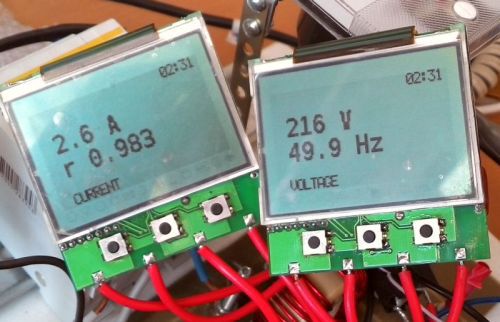
We move on to the final part of the sensor overview cycle, in which we consider DC and AC current and voltage sensors. For all other sensors that did not fall into the main series, we will do additional reviews when they are suddenly needed in future articles.
This article opens a new series of materials about the measurement of electric power quality parameters, which will include the issues of connecting current and voltage sensors to a microcontroller, consideration of the operation algorithms of electric power quality analyzers, the meaning of various power quality indicators and what they mean. In addition, we will touch upon the topic of accuracy of digitization and data processing, which is of concern to many, mentioned in the comments to the first article.
Content
Part 1. Mat. part. It considers a sensor that is not tied to any particular measured parameter. The static and dynamic characteristics of the sensor are considered.
Part 2. Climate control sensors. It discusses the features of working with temperature, humidity, pressure and gas composition
sensors. Part 3. Sensors of electrical quantities. In this part, I will examine current and voltage sensors.
ATTENTION:Do not plug the spokes into the socket.Do not climb into the 220V network without the necessary skills!
It happens direct current, it happens alternating. Everything happens at once, which sometimes brings a lot of problems. But more on that later. For starters, let's deal with terminology.
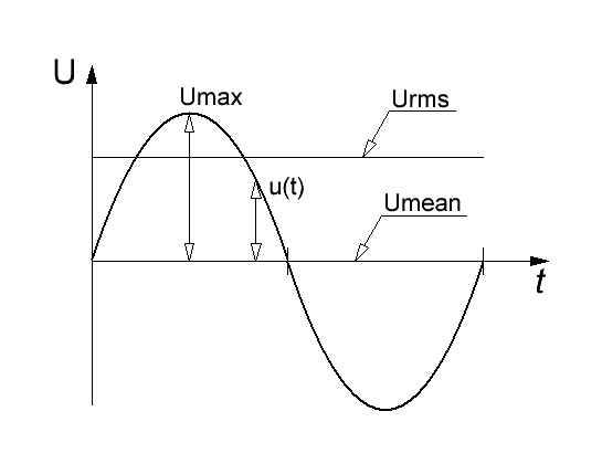
Figure 1: voltage in AC circuits
When measuring AC, we have 4 different values that will guide us in the measurements. All formulas and terms below apply to the current meter.
1. The instantaneous voltage value is the potential difference between two points. Measured at a specific point in time. This value is basic in all other calculations. In fact, our task will be to read a sequential set of instantaneous voltage values at regular intervals, so that later they can be used to obtain some other data.
u = u (t) (1) You will
get approximately the following graph:
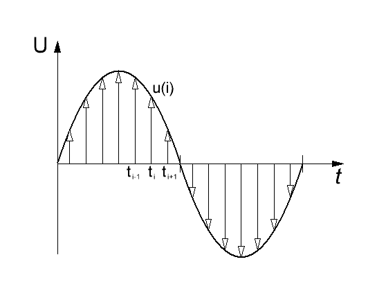
Figure 2: Measurement of a series of instantaneous voltage values
When choosing a frequency for polling sensors, we are guided by the Kotelnikov-Shannon theorem when, in order to restore a signal with frequency f, it is necessary to read with frequency than 2f. I note the need for strict inequality, that is, if we need to digitize a signal with a frequency of 50 Hz, then reading must be done with a frequency of at least 101 Hz. But, of course, the more the better.
If we recall GOST on the indicators of the quality of electricity, then in the Harmonics section we find that harmonics up to 40, i.e. up to 2 kHz, are interesting for our measurement. And the chips of the electricity meters read 4096 times per second. The power of two is chosen so that fast Fourier transform algorithms can be applied.
Having this large set of data collected per unit of time, for example, 1 s, we proceed to the following:
2. The amplitude value of the voltage — which is defined as the maximum modulus value from our sample:
 (2)
(2) where [u (t)] is the data array.
For harmonic oscillations, this value is used in the following formula:
 (3)
(3) 3. The average voltage value,i.e. the arithmetic mean, i.e., the constant component of the alternating voltage.
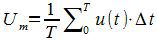 (4)
(4) Where
 is the sampling period of the analog signal. I intentionally write the sum instead of the integral. In an industrial AC network, the average value should be zero. If this condition is not met, there may be certain problems, since direct current biases the transformers, introducing them into saturation, or heats up the supply line. The latter incidentally can be useful for solving the problem of frozen ice on wires - the wire is heated and the ice falls off.
 In low-current analog circuits, the constant component is present all the time and can be very useful. And if it will bother us, then we will quickly get rid of it, but more on that later.
4. The rms value of the voltage . - also known as the effective voltage value - on the linear active load it performs the same work as a constant voltage of a similar level. It is determined by the following formula:
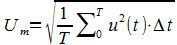 (5)
(5) When measuring the voltage in the outlet, as a rule, we are interested in this very effective voltage, which is 230 / 380V.
The amplitude and current values of the sinusoidal voltage are interconnected through
 . During the design of the measuring system, we will be primarily interested in precisely the amplitude value of voltage and current.
 During measurements we will be guided by one of the following schemes:
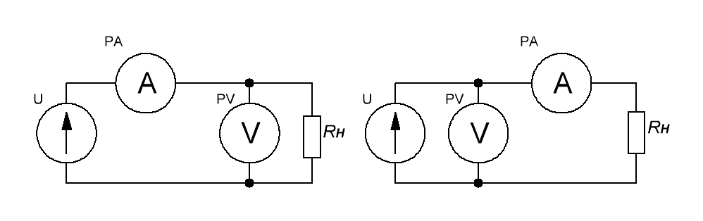
Figure 3: Connection of measuring instruments
A riddle for the mind - both connection schemes are correct, but under what circumstances is it important to choose one of them correctly? Answers in the comments.
Voltage sensors
The first step is to measure the voltage. All of the following applies to voltages of at least the ADC supply voltage of our controller. Thus, we need to measure the voltage with an amplitude greater than the ADC is able to chew. Therefore, the voltage level must be reduced - i.e. to attenuate the signal.
For low voltages (for example, like thermoEMF of a thermocouple from the previous article), the inverse problem is needed - signal amplification. This is a more difficult task and we will definitely return to it in the following articles.
We set the condition for calculating our sensors:
Measured voltage: alternating, 0-1000V, frequency 50 / 60Hz. For a three-phase voltage of 380V, the amplitude is almost 600V, and there are networks at 660V. So let it be. In fact, I took this calculation from my piece of iron and redo it for me laziness.
Output voltage ± 1.65V - half of the supply + 3.3V
Voltage divider
The easiest way would be a voltage divider.
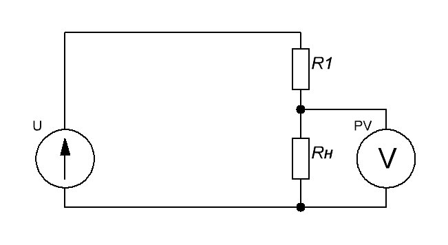
Figure 4: Voltage divider The voltage
on our measuring device will be determined as the input voltage multiplied by the divider coefficient:
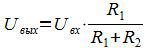 (6)
(6) When choosing the resistance of the resistors, it is necessary to determine the following requirements:
1. The current through the resistor circuit should be 1-2 orders of magnitude greater than current of our measuring device so that this current does not affect the readings. The meter has a finite resistance value and it turns out that another resistor is connected to the resistor R2. The greater the internal resistance, the closer the overall resistance to the resistance R2. The resistance of the internal circuits of the ATmega ADC, for example, is 100 MΩ.
2. The power allocated to our divider should not be too large
3. The applied input voltage should be less than the breakdown voltage of the resistor.
Let the current through our maker be 1mA. Then, the total resistance of the resistors will be equal to:
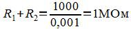 (7)
(7) We will determine the required transfer coefficient of our divider:
 (8)
(8) For a series of resistors E24, we select the closest value giving about 1MΩ:
R1 = 990 kOhm (three resistors of 330 kOhm)
then the resistor R2 = K · R1 = 1.63 kOhm
From the E24 series we select the second resistor R2 = 1.6 kOhm. We
check the coefficient:
 (9)
(9)The error with the previously calculated 2.3%, which will suit us. Actually, you can accurately select the resistors from the E192 series, but in my case it is not necessary - a voltage of 1000V at the input is an abnormal mode, and the system will still be calibrated later.
The measuring circuit will look like this:

Figure 5: Voltage meter circuit
When developing a voltage divider for large operating voltages, the maximum allowable voltages for the resistors used must be taken into account.
For example, the rated operating voltage for SMD resistors is 15 V (0201); 50 V (0402, 0603); 150 V (0805); 200 V (1206, 2010, 2512),
and the maximum permissible - 50 V (0201); 100 V (0402,0603); 200 V (0805); 400 V (1206, 2010, 2512).
That is why I use three series-connected resistors of size 1206 - they fit into 555 volts of working and 1000V maximum permissible.
Of course, all these resistors must be high-precision, since the accuracy of measurement depends on their resistance and thermostability of this resistance.
On the basis of the R4-C1 chain, a low-pass filter is assembled so that no interference is frightening to us. By the way, we can quickly see what this filter does:
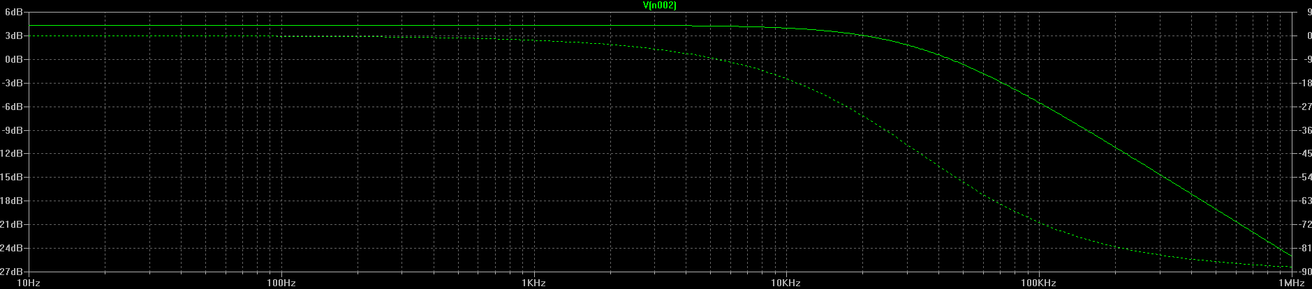
Figure 6: Filter frequency response
As can be seen from the LAC curve, for the operating frequency range from 0 to 2000 Hz, the filter practically does not spoil the signal amplitude and phase. But the interference at frequencies of the order of 100 kHz and above, emanating from high-frequency converters, reliably crush. So everything is super.
Advantages:
- a wide range of voltages and frequencies, determined by the values of the resistors;
- high accuracy, again determined by the accuracy and thermal stability of the resistors;
- Measures direct and alternating voltage.
Disadvantages:
- there is no galvanic isolation - when interacting with an industrial network, it is necessary to provide for the protection of the user from electrical circuits, or use galvanic isolation;
- low efficiency - all the divider current goes into heat;
Voltage transformer
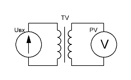
Figure 7: Voltage transformer
For cases when it is necessary to measure very high voltages, 6 / 10kV and higher, a voltage transformer is used. In fact, it is a normal transformer, the main mode of operation of which is idle mode.
The accuracy class of such a transformer depends on the working area of the magnetization characteristic. After all, we need to pass through it not just a signal with a certain amplitude, but also not to spoil its shape. This is precisely the problem - most voltage transformers practically do not pass harmonics. It's all about the metal core and the magnetization reversal losses. Moreover, the thinner the core plate. the better its frequency response.
The usual accuracy class of the transformer is 0.5, 1, 3
Advantages:
- a huge range of operating voltages - up to hundreds of kilovolts and above;
- much needed galvanic isolation.
Disadvantages:
- works on a certain frequency band;
- works only with alternating voltage;
The last drawback is slightly contrived, because if necessary, you can use a direct current measuring transformer. Yes, DC transformers "exist", but the correct name for the device is a magnetic amplifier. The accuracy and linearity of such devices leaves much to be desired - work occurs on the saturation area of the core by magnetization.
It looks like this:

Figure 8: Measurement of direct current with a magnetic amplifier
You can read about this miracle of technology here: analogiu.ru/6/6-2-2.html
If the topic is interesting, then I will give an overview of these ancient controllers.
Electronic isolated sensor
The disadvantages of both circuits are deprived of an electronic isolated sensor. In fact, it is a complete device. Inside which there is a voltage divider, and operational amplifiers, and a galvanic isolation unit and an isolated power supply circuit for all this disgrace:
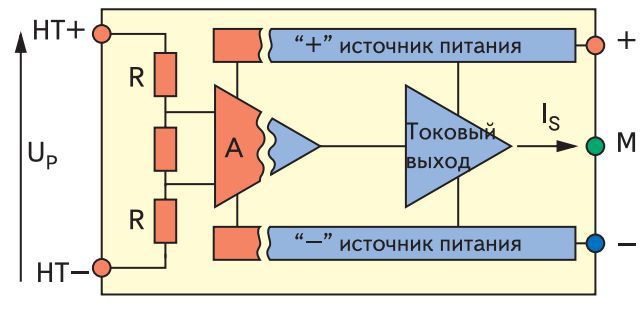
Figure 9: Block diagram of an electronic isolated sensor
I came across only industrial sensors with an output of 0-10V or 0- current 10mA. Unlike previous sensors, it produces a unipolar signal. In principle, such a scheme can be developed independently, applying, for example. Isolated analog amplifier like the HCPL-7850 . The main drawback of the scheme is very complicated and very expensive.
And as correctly noted in the comments of Comrade progchip666
It is extremely difficult to transmit an analog signal with an accuracy of even one percent through a galvanically isolated interface, so often in this case you have to overtake it into a digital one and already overtake it in this form.
Unfortunately, the amplifier shown in the diagram also needs to be supplied with power. Of course from a galvanically isolated source.
Advantages:
- galvanic isolation;
- high accuracy;
- wide range of voltages and frequencies;
- Measures direct and alternating voltage.
Disadvantages:
- expensive;
- complex circuitry.
Sitelinks
current and voltage sensors ABB www.power-e.ru/2006_03_56.php
current and voltage sensors LEM www.sensorica.ru/pdf/LEM.pdf
Power meters STMP32 www.compel.ru/lib/ne/2015/4/2 -dlya-odnofaznyih-i-mnogofaznyih-schetchikov-novyie-izmeritelnyie-mikroshemyi-ot-st en.wikipedia.org/wiki/Electric voltage
Current sensors
Measuring shunt
The easiest and most accurate way to measure current. As you know, when a current flows through an active resistance, a voltage drop occurs on it, proportional to the measured current. Well, we take a resistor and put it in the gap of the measured circuit:
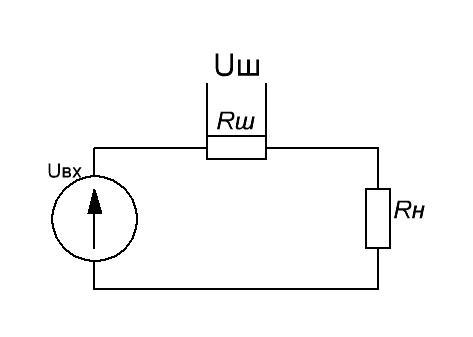
Figure 10: Current sensor current shunt
The voltage drop across the shunt is proportional to the transmitted current:
 (10)
(10)Accordingly, depending on the required voltage at the output of the sensor, we select the desired shunt resistance. But! The voltage drop on the shunt will lead to power losses released to the heat, respectively, at high currents we are forced to be content with low voltage values from the sensor in order to limit losses. These ShSM-type shunts manufactured by the industry provide a standard output voltage of 75mV at rated current:
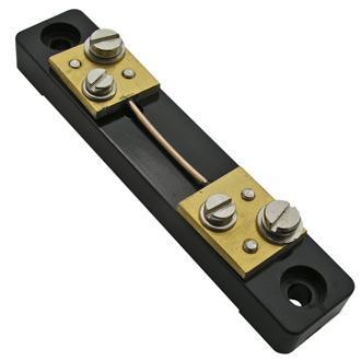
Figure 11: ShSM-type current shunt.
For most shunts, a voltage of 75mV is calibrated. Pay attention to the second pair of screws - they are designed specifically for connection to a measuring device to increase the accuracy of measurements by separating the currents of the power and measuring circuits ...
Operational amplifiers are required to measure current using such shunts. At the same time, the average gain is 20-40, which can be achieved by widespread operational amplifiers. In principle, in non-critical DC circuits, one can also use an amplifier stage based on a single transistor. The linearity of such a scheme will be lame, but for threshold protection circuits it is a simple and reliable option.
We get the following circuit:

Figure 12: Using the op-amp as an amplifier
It should be noted that when measuring AC, the output signal will be bipolar and the operational amplifier needs to be powered from a bipolar power source.
Just in case, our circuit works:
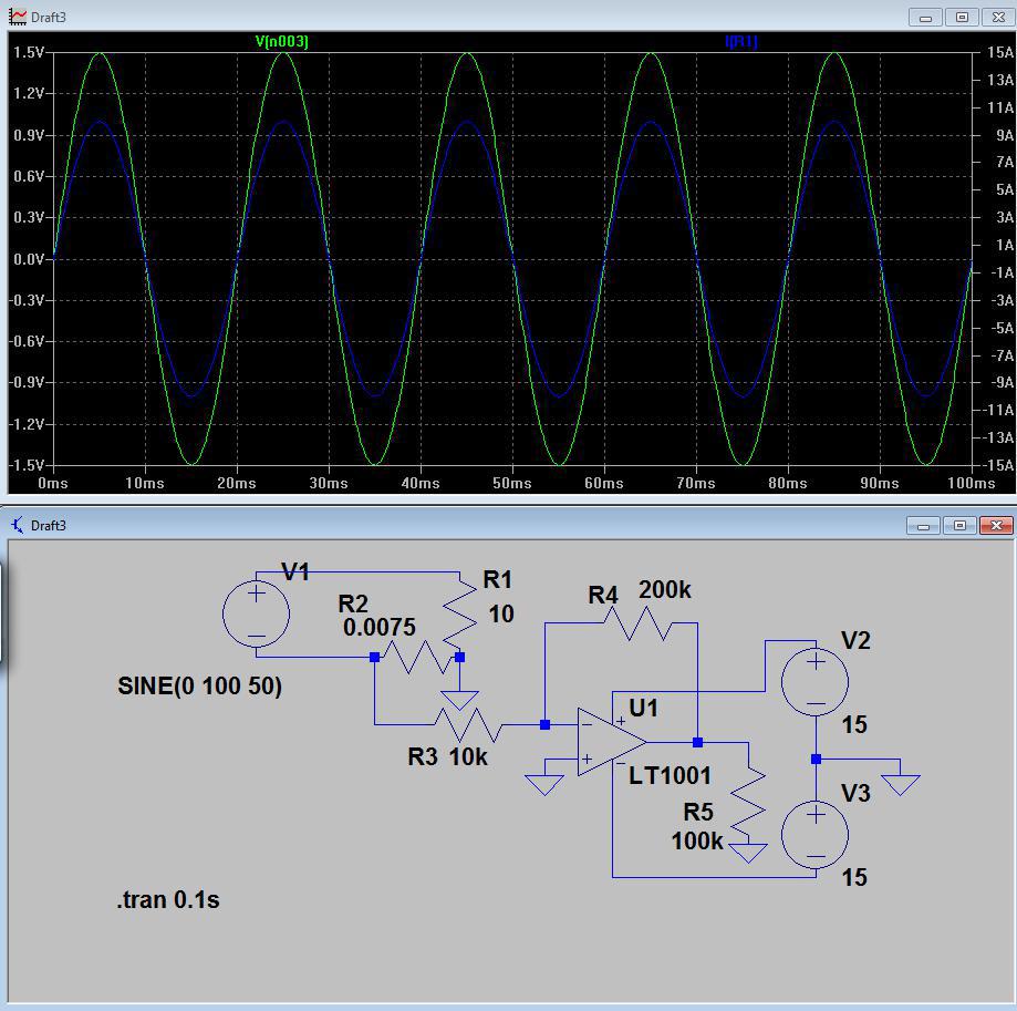
Figure 13: Simulation of a current sensor amplifier
We feed 75mV to the input, multiply by 20, and we get a signal with an amplitude of 1.5V for a current of 10A at the output. In the next article we will understand how a bipolar signal can be inconvenient.
Advantages :
- high accuracy;
- wide range of voltages and frequencies;
- measures direct and alternating current.
Disadvantages:
- there is no galvanic isolation;
- low efficiency.
Current transformer
The measuring current transformer is a transformer whose primary winding is connected to a current source, and the secondary is closed to measuring instruments or protective automation devices.
Current transformers are used to measure currents in high current circuits, often I have high potential. For example, we wanted to measure the current in a 10kV network. Or, we want to get a simple and relatively cheap way to galvanically decouple the measured current circuit of our device to 220V. The main problem of current transformers is that they can only measure alternating voltage.
The current transformer is always loaded. If the secondary winding of the current transformer turns out to be open, then a potential of a couple of thousand kilovolts will appear on it, which will cripple the staff and disable the device, breaking its insulation.
Transformers come with a built-in primary winding. For example, these are:

Figure 14: Coilcraft CS2106L series current transformer
Either these elephants having the appearance of a primary winding in the form of a huge bus, or even a window for passing wires through it
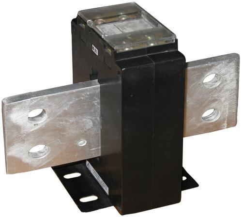
Figure 15: Many ampere industrial current transformer
The main disadvantage of the current transformer is that it only works at a certain frequency of 50, 60 or 400 Hz due to the metal core. Of course, a current transformer is able to transmit a signal of a higher frequency, but with much less accuracy. In this case, you should pay attention to the thickness of the sheet of the core used - the thinner the iron in the current transformer, the higher the maximum permissible operating frequency. By the way, there are current transformers from ferrite, which are used to measure systems with a frequency of 50-60 or more kHz. For example, the CS1 series from Coilcraft is designed to operate in the 20-50kHz range and may find application in switching power supplies.
But if we remove it, we get an air transformer, or, so-called. Rogowski Coil:
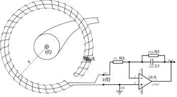
Figure 16: Connection diagram of the Rogowski coil
Unlike other sensors that require interaction with the measured circuit, the Rogowski coil can be installed over the wires of the measured circuit as a belt.
Some measuring instruments are equipped with such sensors:
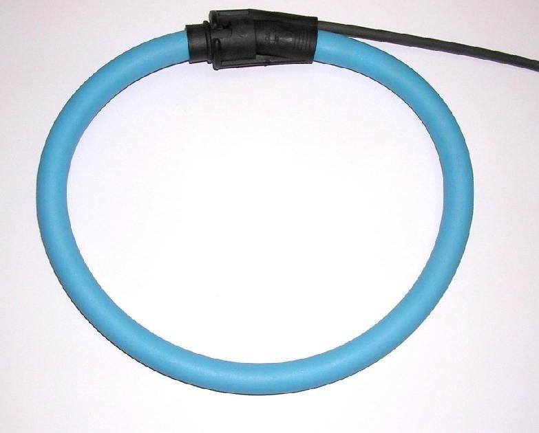
Figure 17: Rogowski coil sensor The
range of measured currents is from tens to thousands of amperes, but they suffer from poor accuracy.
Advantages:
- galvanic isolation;
- work with large currents of thousands of amperes;
Disadvantages:
- measures only alternating current in a certain frequency range (except for the Rogowski coil);
- changes the phase of the signal and requires compensation
Hall effect current sensors
Sensors of this type use the effect of the occurrence of a potential difference when a conductor with a current is placed in a magnetic field.

Figure 18: Hall effect
When creating a sensor, we take a magnetic circuit, pass the wire of the measured circuit through it and put a Hall sensor in the section of the magnetic circuit, obtaining an open type current sensor:
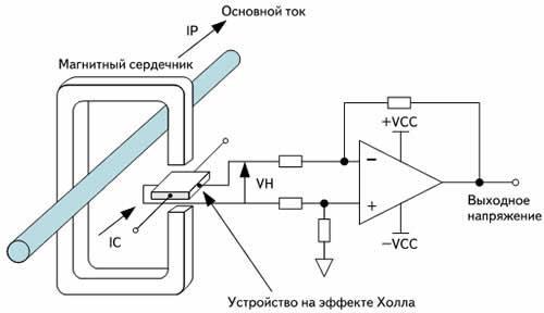
Figure 19: Current sensor based on an open type Hall effect The
advantage of such a sensor is its simplicity. The disadvantage is the presence of magnetization of the core, therefore, an increase in the nonlinearity of the readings.
Add a winding to the core and run a current proportional to the measured current along it:
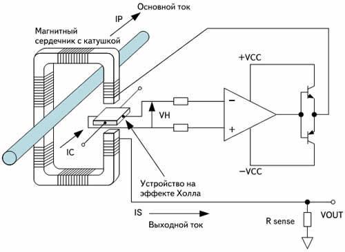
Figure 20: Compensation-type Hall effect current sensor
With zero magnetization of the core, we increase the linearity of the sensor and its accuracy class. However, in its design, such a sensor approaches current transformers, respectively, its cost increases significantly.
Like transformers, there are varieties of sensors that allow you to let a power wire pass through you:
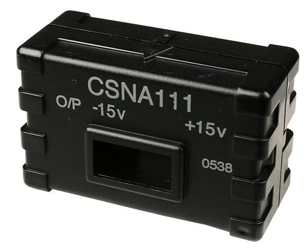
Figure 22: Hall effect current sensor
There are sensors with a shared core - however, their cost is too high.
Sensors with an integrated power circuit based on the Hall effect with galvanic isolation of 2.1kV and 3kV are manufactured by Allegro. Due to their small size, they do not provide high accuracy, but they are compact and easy to use.
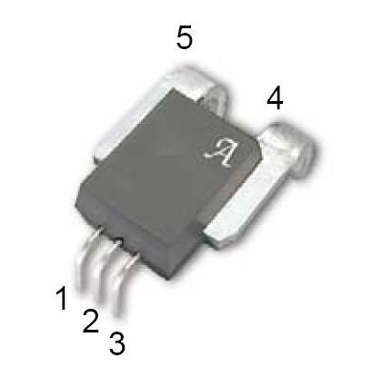
Figure 23: Allegro ACS754 Current Sensor
- ACS712 sensor - measurement of direct and alternating current up to 30A with an accuracy of ± 1.5%
- ACS713 Sensor - Optimized for measuring DC current up to 30A. It has twice as much sensitivity as its universal counterpart.
- ACS754 sensor - measurement of direct and alternating current up to 200A with an accuracy of ± 1.5%
- ACS755 Sensor - Optimized for DC measurement.
- The ACS756 sensor is a sensor for measuring direct and alternating current up to 100A with a supply voltage of 3-5V.
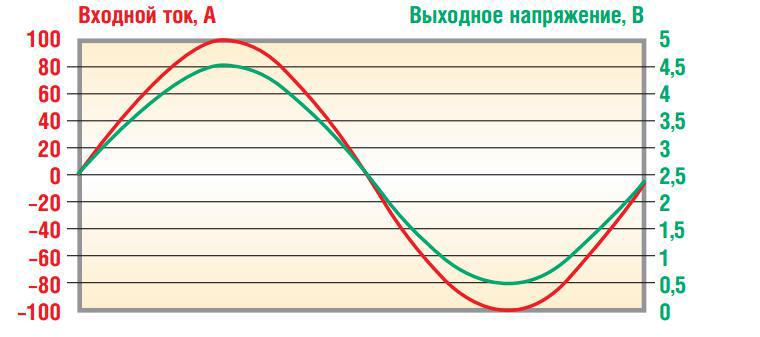
Figure 24: Dependence of the output voltage of the sensor on the current
Advantages :
- wide range of measured currents with a frequency of up to 50-100 kHz and higher;
- measures direct and alternating current.
- galvanic isolation
Disadvantages :
- Expensive
Additional links:
Measuring DC transformers analogiu.ru/6/6-2-2.html
Rogowski coil www.russianelectronics.ru/leader-r/review/2193/doc/54046
Hall Effect in Wikipedia: ru.wikipedia.org/wiki/Effekt_Holla
Hall sensors robocraft.ru/blog/electronics/594.html
Danilov A. Modern industrial current sensors www.soel.ru/cms/f/?/311512.pdf
Designing circuits based on the analog amplifier HCPL-7851 www.kit-e. com / assets / files / pdf / 2010_04_26.pdf
Conclusion
I set myself the task of creating an overview of the sensors, the most commonly used community in the development of various devices. Most of the sensors were not included in the cycle just for the reason that in the near future they will not be needed for my materials, but some of them are planned. Be sure to make a separate material with acceleration sensors, angular velocities, a compass and examples, so stay tuned for new articles!









