Motion sensor for switching radio stations - part I
Hello, Habr! From this text you will understand that I began to read “Young Radio Amateur” and fell in love with this book and its author, and now I really want to do something similar for those who take their first steps with Arduino - so that it is simple and clear.
The principle of echolocation to determine the distance to the object is the basis of the motion sensor, which we will use.
I hope this article will be interesting not only for beginners, but also will save time for more advanced users, as I tried to collect information on an ultrasonic rangefinder in one place, including datasheets, TTX, specs, illustrations and libraries from various sources.
In the last postwe almost automatically collected a couple of shields and reprogrammed our MK under one and under the other. It was no more difficult than uploading a new song to the player. Thus, we learned how, in principle, it is possible to play with this constructor, and we can continue to play like that, changing ready-made shields and sketches. But I want to collect something of my own.
So let's try almost seriously and without fear to look into the eyes of circuitry and programming, and independently add an additional sensor to the finished circuit. For the entire time of the text you have to pick up a soldering iron for about 10 seconds, sorry if that.
What we learn during the assembly of a new device:
1. How to read the finished device diagram (the so-called circuit diagram) and find there what we need.
2. What pins are on Arduino and why. How to choose the right one.
3. How to ping a new component from a computer (port monitor in the IDE). How to verify that the new component is working.
4. We will get to know a little how one of the sketches is written.
5. How to add an ultrasonic sensor to the finished radio circuit.
Task: add a new component to the finished radio device: an ultrasonic distance sensor in order to switch stations with its help.
If you have only Arduino herself and this sensor, you can also participate in this project and almost completely repeat all the steps described in the text. In this case, you will stop at the moment when you set up such an interesting ultrasonic line. I want to go further and try to tune the radio station with a wave of my hand. So.
Solution:
As you recall, I have a beginner kit , which includes a ready-made expansion board for Arduino with all the necessary set of components to assemble the radio. The radio is going to be no more complicated than the Lego designer according to the instructions, or even without, because most of the components simply cannot be put “incorrectly” on the board - their legs are so conveniently located. At the initial stage, the radio looks like this:
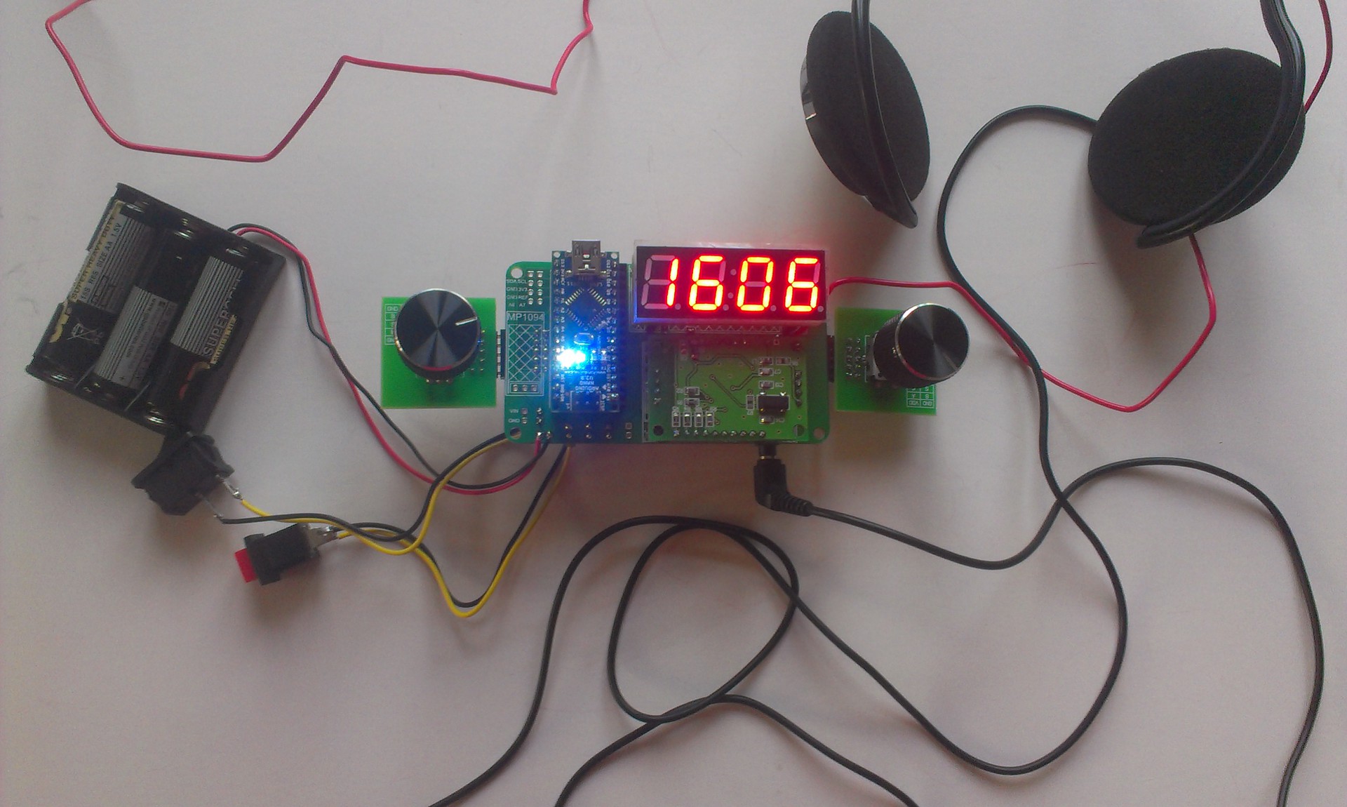
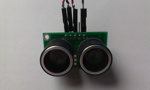
Which in itself is wonderful. A recent handful of "details" began to play live music with me. However, this is not enough for me and I want to add this sensor here, get acquainted:
Name: ultrasonic range finder type HC-SR05
For googling: 5 pin ultrasonic, ultra-sonic ranger SRF05
Libraries:
NoBlind_Ultrasonic , which I use in my
NewPing project , which, as the author promises, it is distinguished by a higher speed of work.
Datasheet in Russian: TTX in pdf
Excellent datasheet: specification in English, the most complete
Wiki-site, datasheet: briefly, in English
Designation on the diagram:

For a start, a little entertaining physics.
They work on the principle of dolphins, bats and whales. Some of these guys have poor eyesight, someone in the water or at night is not particularly visible, like any normal person. Therefore, they rely on sound. This principle is echolocation: they send sound, it reaches the object and, reflected from it, returns. Because, roughly speaking *, the speed of sound is fixed, so you can understand how much to the object, if you know how much the sound returned.
This guy can fly at night and not crash into you and other trees, because he measures the distance to objects with ultrasound. =)
A person can find out how far the storm is: first we see lightning (because the speed of light is faster), and then we hear thunder. If you count how many seconds the distance between the flash and the thunder, and know the speed of sound - 340.29 m / s, then you can calculate the distance to the thunderstorm in meters:
We do not hear the sound used by the sensor, since our ear does not hear vibration at frequencies above 20 kHz. But animals hear this sound.

The range of sounds audible to us is from 20 Hz to 20 kHz, i.e. our ear cuts off infrasound and ultrasound.
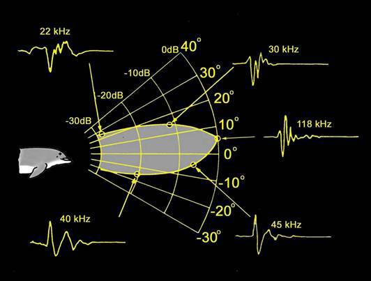
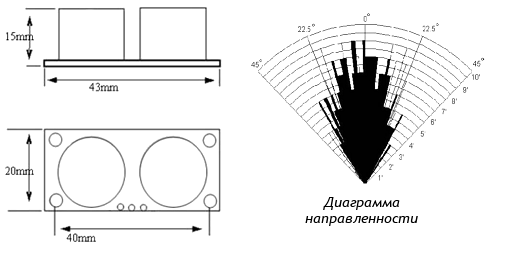
Rodent repellers are based on this principle. In order not to upset your pets, do not poke them with a working sensor in your ear, because for them it works very loudly. Fortunately, it sends sound to a distance no further than 200-400 cm, i.e. the animal may simply move away from the sound source and not listen to it. Also, the sound from the sensor “pours” not in all directions, but mainly forward, scattering on the sides - you will feel it when, when tuning in the radio, you try to put your hand strictly above the sensor itself so that your hand better “sees” the device:
In any case, if there are animals at home, then for stationary projects, perhaps you better use other motion sensors. So, for example, the distance can be measured using infrared rays, in this case, take the IFC sensor.
And one more important point. You will not be able to switch radio stations, for example, with a cat. The fact is that sound is reflected somehow from fluffy objects, namely, it is absorbed by them. That is why the walls are upholstered with something soft at the repbase: it is soundproofed so that musicians cannot be heard while they are playing at full volume in the studio (well, or beating against the wall with your head - that’s how it works).
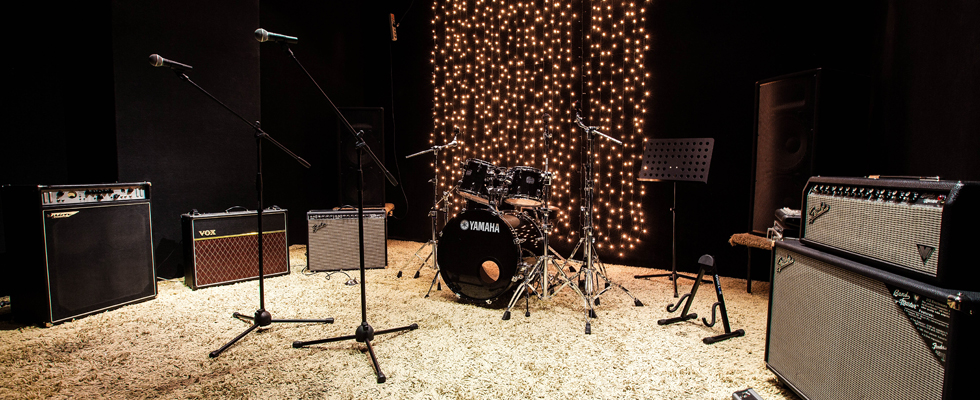
The soft floor at the rehearsal base not only collects dust, but also absorbs sound.
As can be seen from the table, we are not much mistaken if, in calculating the distance to the thunderstorm, we take the speed of sound for 340 m / s.
Although it’s hard for me to fully understand this video about the principles of operation of ultrasonic sensors directly because of the many terms and the fast pace, it’s very pleasant to watch and listen to it.
Assignment: if you were able to watch the video above, then try to answer the question why our sensor has two sensors on the same board and write your answer in the comments.
That's it. Congratulations, you are an expert in sound propagation and echolocation! You can move on.
Where to connect the sensor? How to choose a place for him? Is there any free space on our expansion board? Immediately make a reservation that the sensor can be planted both on the expansion board, and directly on the Arduino legs themselves. And how to choose them, we now find out. So.
Take the diagram of our finished shield from here from the section "diagrams". Here's what it looks like:
This is called a circuit diagram. Fundamental because it basically shows what is connected to, but this circuit does not reflect the actual arrangement of components on the board. But it, in theory, is easy and convenient to read. I was initially uncomfortable, because at the end, Arduino doesn’t have a single leg in fact, but in this diagram we see D2-D6 legs on it, which at first simply tore my pattern. But if you get used to it, that schemeso fundamental that it simplifies everything to the state of “squares” and simply answers the question “what is connected to what” - then it becomes easier to work with it.
To read the conventions, you can use a short “dictionary” , but I recommend not doing it now, especially since our diagram mainly reflects ready-made components, not board parts, each of which has its own legend on the diagram. Now, don’t be scared, we’ll try to find a “place” on this diagram for only one new sensor. Please note that the buttons are indicated at the bottom of the diagram:
There are three of them, K1-K3. We already “stuck” them where needed when we assembled the radio according to the instructions. However, there are 2 more “under the buttons” sockets on the board: K4 and K5. They look just like four holes, but marked differently. We are only interested in those pairs of holes that are indicated on the board by a square contact.
This is how we supplement the circuit with a sensor (Photoshop mad skills)
Task: look at the circuit diagram of the entire radio device again. How many legs are Arduino still “free”? Can we hang something else on this Arduino as part of this device besides our ultrasonic sensor? Waiting for your answers in the comments.
Where there are holes on the expansion board for Arduino, we can add the so-called pin connectors \ connectors \ pins, which are indicated by the letters PLS-XXX, where instead of XXX you need the number, depending on the number of pins. They are sold in the form of long combs, from which you can independently separate PLS-1, PLS-2, etc. They look like this:
An irreplaceable thing in the household! If wound up Arduino. So, the K4 and K5 contacts have two holes each, which means they are called PLS-2. We will add one pin to their square part and thus bite off two pieces of PLS-1. Now you can solder.
Instead of a thousand words: this is the same place with the buttons from the diagram above, but now you see it on the board.
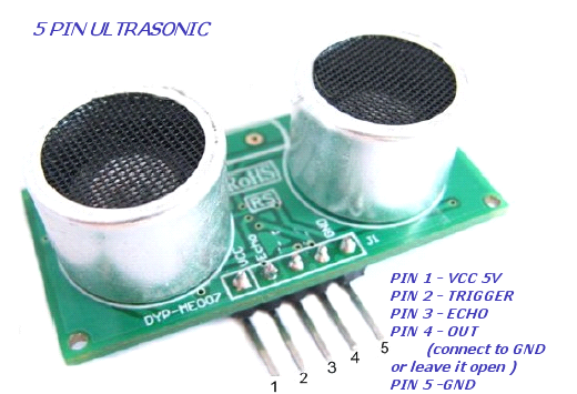
The sensor has 5 pins. They will allow us to “ask him a question”, get a “response”. Well, connect it to the power. Information, which pin means what, can be taken from datasheets or on the store website where you bought the sensor. It is a pity that, as a rule, nothing is signed in detail, therefore, especially for our article - get acquainted with the sensor pins:
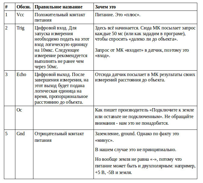
MK is a microcontroller. Our Arduino is a microcontroller that we can program as we want.
What is characteristic, the purpose of the Oc pin even on the most overseas sites remains foggy . They write there: "the purpose of the Oc pin still needs to be hacked." I managed to hack it after a few minutes of googling. In the official datasheetit is written that this contact is not connected to anything, lol .
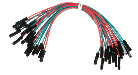
Everything is simple and even predictable here: two contacts for power and two in order to send / receive a signal. Therefore, we take 4 mother-to-mother wires and prepare the sensor for landing on the board:
Until now, everything went well, however, where to connect each of the 4 wires and why?
There is such an anecdote: one person wanted to learn how to make a dead loop. He bought an aviation magazine, where it was described in the article, got on a plane and flew. At first everything went well: he followed the instructions described in the journal and successfully entered the dead loop. Then he turned over the page, and there: read the exit from the dead loop in the next issue .
We are lucky that we do not learn to make a dead loop according to my articles. Because now I will give you a little rest. I hope so far it has been clear and interesting to read. Now you have some time until I prepare the second, final part of the post, where we will figure it out:
We will answer the remaining questions and collect the finished device, as well as program it. Subscribe to updates - I will be pleased.
Right now, I suggest you answer this question: what is more interesting for you in Arduino - to assemble components or program a device? Why?
The principle of echolocation to determine the distance to the object is the basis of the motion sensor, which we will use.
I hope this article will be interesting not only for beginners, but also will save time for more advanced users, as I tried to collect information on an ultrasonic rangefinder in one place, including datasheets, TTX, specs, illustrations and libraries from various sources.
In the last postwe almost automatically collected a couple of shields and reprogrammed our MK under one and under the other. It was no more difficult than uploading a new song to the player. Thus, we learned how, in principle, it is possible to play with this constructor, and we can continue to play like that, changing ready-made shields and sketches. But I want to collect something of my own.
So let's try almost seriously and without fear to look into the eyes of circuitry and programming, and independently add an additional sensor to the finished circuit. For the entire time of the text you have to pick up a soldering iron for about 10 seconds, sorry if that.
What we learn during the assembly of a new device:
1. How to read the finished device diagram (the so-called circuit diagram) and find there what we need.
2. What pins are on Arduino and why. How to choose the right one.
3. How to ping a new component from a computer (port monitor in the IDE). How to verify that the new component is working.
4. We will get to know a little how one of the sketches is written.
5. How to add an ultrasonic sensor to the finished radio circuit.
Task: add a new component to the finished radio device: an ultrasonic distance sensor in order to switch stations with its help.
If you have only Arduino herself and this sensor, you can also participate in this project and almost completely repeat all the steps described in the text. In this case, you will stop at the moment when you set up such an interesting ultrasonic line. I want to go further and try to tune the radio station with a wave of my hand. So.
Solution:
As you recall, I have a beginner kit , which includes a ready-made expansion board for Arduino with all the necessary set of components to assemble the radio. The radio is going to be no more complicated than the Lego designer according to the instructions, or even without, because most of the components simply cannot be put “incorrectly” on the board - their legs are so conveniently located. At the initial stage, the radio looks like this:
Which in itself is wonderful. A recent handful of "details" began to play live music with me. However, this is not enough for me and I want to add this sensor here, get acquainted:
Name: ultrasonic range finder type HC-SR05
For googling: 5 pin ultrasonic, ultra-sonic ranger SRF05
Libraries:
NoBlind_Ultrasonic , which I use in my
NewPing project , which, as the author promises, it is distinguished by a higher speed of work.
Datasheet in Russian: TTX in pdf
Excellent datasheet: specification in English, the most complete
Wiki-site, datasheet: briefly, in English
Designation on the diagram:
For a start, a little entertaining physics.
What you need to know about ultrasonic distance sensors
They work on the principle of dolphins, bats and whales. Some of these guys have poor eyesight, someone in the water or at night is not particularly visible, like any normal person. Therefore, they rely on sound. This principle is echolocation: they send sound, it reaches the object and, reflected from it, returns. Because, roughly speaking *, the speed of sound is fixed, so you can understand how much to the object, if you know how much the sound returned.
This guy can fly at night and not crash into you and other trees, because he measures the distance to objects with ultrasound. =)
A person can find out how far the storm is: first we see lightning (because the speed of light is faster), and then we hear thunder. If you count how many seconds the distance between the flash and the thunder, and know the speed of sound - 340.29 m / s, then you can calculate the distance to the thunderstorm in meters:
Speed = Time * Distance
For example:
20s * 340m / s = 6800m = 6.8 km
We do not hear the sound used by the sensor, since our ear does not hear vibration at frequencies above 20 kHz. But animals hear this sound.
The range of sounds audible to us is from 20 Hz to 20 kHz, i.e. our ear cuts off infrasound and ultrasound.
Rodent repellers are based on this principle. In order not to upset your pets, do not poke them with a working sensor in your ear, because for them it works very loudly. Fortunately, it sends sound to a distance no further than 200-400 cm, i.e. the animal may simply move away from the sound source and not listen to it. Also, the sound from the sensor “pours” not in all directions, but mainly forward, scattering on the sides - you will feel it when, when tuning in the radio, you try to put your hand strictly above the sensor itself so that your hand better “sees” the device:
In any case, if there are animals at home, then for stationary projects, perhaps you better use other motion sensors. So, for example, the distance can be measured using infrared rays, in this case, take the IFC sensor.
And one more important point. You will not be able to switch radio stations, for example, with a cat. The fact is that sound is reflected somehow from fluffy objects, namely, it is absorbed by them. That is why the walls are upholstered with something soft at the repbase: it is soundproofed so that musicians cannot be heard while they are playing at full volume in the studio (well, or beating against the wall with your head - that’s how it works).
The soft floor at the rehearsal base not only collects dust, but also absorbs sound.
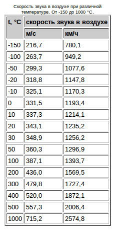
* More precisely , the speed of sound is also affected by the temperature and density of the medium in which it propagates.
The hotter the air, the faster the sound propagates, because the speed of sound in gases increases with increasing temperature. With an increase in air temperature of 1 °, the speed of sound in it increases by 0.59 m / s. In our situation with a thunderstorm, the scatter in the values of the speed of sound is not so big , therefore the speed of sound is more or less fixed for us: in winter, when there is no frost, there is no thunderstorm, and in summer, when +50 - +100 - as a rule, us. =) If you want to know more about the propagation of sound waves, then, for example, I liked this article .
As can be seen from the table, we are not much mistaken if, in calculating the distance to the thunderstorm, we take the speed of sound for 340 m / s.
Although it’s hard for me to fully understand this video about the principles of operation of ultrasonic sensors directly because of the many terms and the fast pace, it’s very pleasant to watch and listen to it.
Assignment: if you were able to watch the video above, then try to answer the question why our sensor has two sensors on the same board and write your answer in the comments.
That's it. Congratulations, you are an expert in sound propagation and echolocation! You can move on.
Mounting the sensor on an expansion board for Arduino
Where to connect the sensor? How to choose a place for him? Is there any free space on our expansion board? Immediately make a reservation that the sensor can be planted both on the expansion board, and directly on the Arduino legs themselves. And how to choose them, we now find out. So.
Take the diagram of our finished shield from here from the section "diagrams". Here's what it looks like:
This is called a circuit diagram. Fundamental because it basically shows what is connected to, but this circuit does not reflect the actual arrangement of components on the board. But it, in theory, is easy and convenient to read. I was initially uncomfortable, because at the end, Arduino doesn’t have a single leg in fact, but in this diagram we see D2-D6 legs on it, which at first simply tore my pattern. But if you get used to it, that schemeso fundamental that it simplifies everything to the state of “squares” and simply answers the question “what is connected to what” - then it becomes easier to work with it.
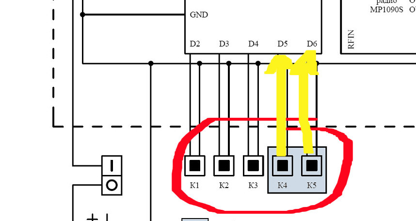
To read the conventions, you can use a short “dictionary” , but I recommend not doing it now, especially since our diagram mainly reflects ready-made components, not board parts, each of which has its own legend on the diagram. Now, don’t be scared, we’ll try to find a “place” on this diagram for only one new sensor. Please note that the buttons are indicated at the bottom of the diagram:
There are three of them, K1-K3. We already “stuck” them where needed when we assembled the radio according to the instructions. However, there are 2 more “under the buttons” sockets on the board: K4 and K5. They look just like four holes, but marked differently. We are only interested in those pairs of holes that are indicated on the board by a square contact.
Note to the hostess:
Why do the buttons have two contacts, and we use one at a time?.
- Square contacts lead to Arduino lines D5 and D6. Round is "earth."
- To connect the buttons, you need two contacts, because when the button is pressed, the signal line closes (pulled up to power through the resistor) and ground.
- When the sensor is connected, earth is only needed for power. We will take the earth a little later from the Arduino connector, so in our case the second contacts will not be needed
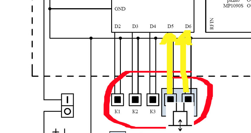
This is how we supplement the circuit with a sensor (Photoshop mad skills)
Task: look at the circuit diagram of the entire radio device again. How many legs are Arduino still “free”? Can we hang something else on this Arduino as part of this device besides our ultrasonic sensor? Waiting for your answers in the comments.
To solder!
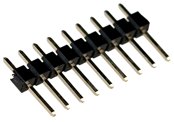
Where there are holes on the expansion board for Arduino, we can add the so-called pin connectors \ connectors \ pins, which are indicated by the letters PLS-XXX, where instead of XXX you need the number, depending on the number of pins. They are sold in the form of long combs, from which you can independently separate PLS-1, PLS-2, etc. They look like this:
An irreplaceable thing in the household! If wound up Arduino. So, the K4 and K5 contacts have two holes each, which means they are called PLS-2. We will add one pin to their square part and thus bite off two pieces of PLS-1. Now you can solder.
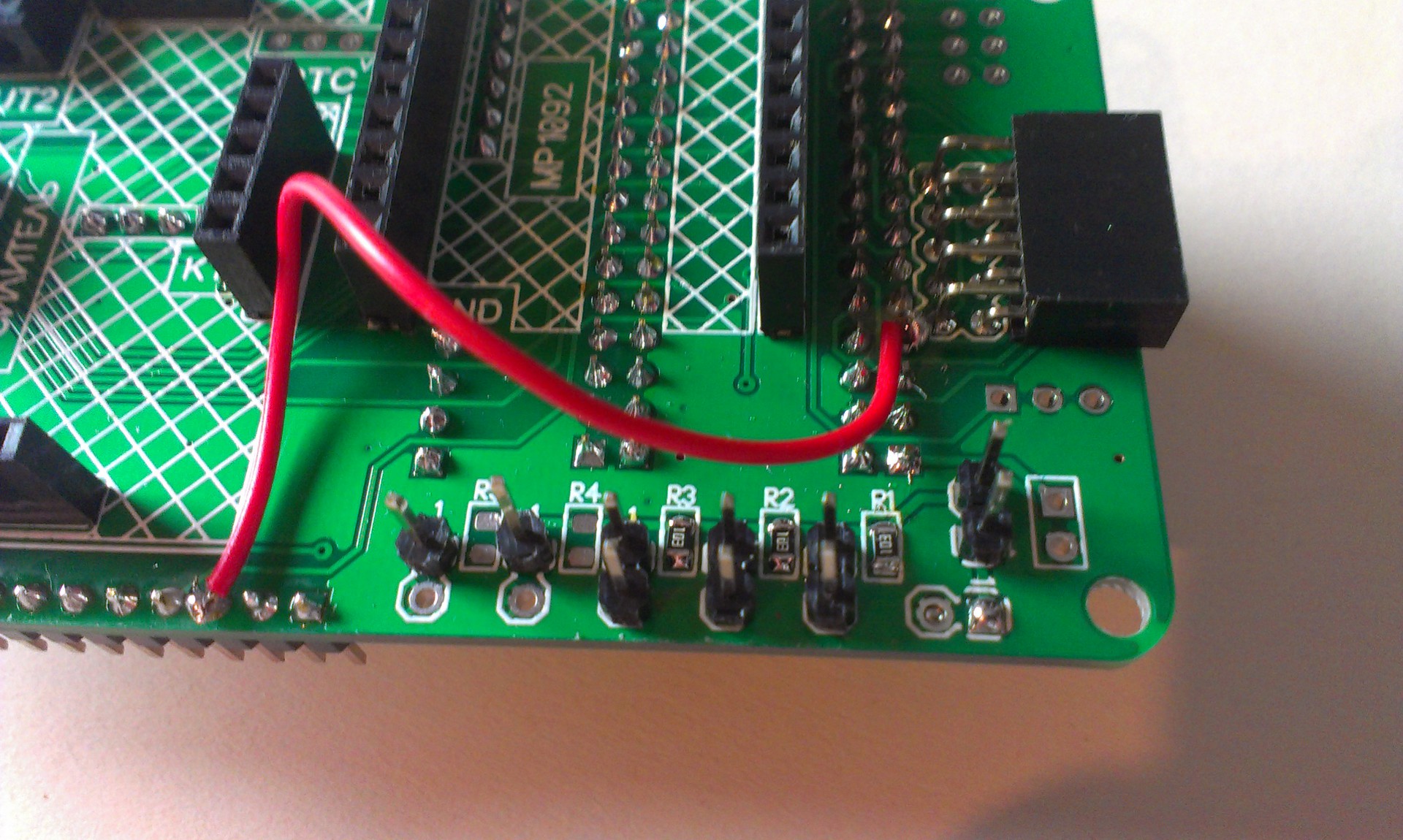
Instead of a thousand words: this is the same place with the buttons from the diagram above, but now you see it on the board.
Sensor Pins
The sensor has 5 pins. They will allow us to “ask him a question”, get a “response”. Well, connect it to the power. Information, which pin means what, can be taken from datasheets or on the store website where you bought the sensor. It is a pity that, as a rule, nothing is signed in detail, therefore, especially for our article - get acquainted with the sensor pins:
MK is a microcontroller. Our Arduino is a microcontroller that we can program as we want.
What is characteristic, the purpose of the Oc pin even on the most overseas sites remains foggy . They write there: "the purpose of the Oc pin still needs to be hacked." I managed to hack it after a few minutes of googling. In the official datasheetit is written that this contact is not connected to anything, lol .
Everything is simple and even predictable here: two contacts for power and two in order to send / receive a signal. Therefore, we take 4 mother-to-mother wires and prepare the sensor for landing on the board:
Until now, everything went well, however, where to connect each of the 4 wires and why?
There is such an anecdote: one person wanted to learn how to make a dead loop. He bought an aviation magazine, where it was described in the article, got on a plane and flew. At first everything went well: he followed the instructions described in the journal and successfully entered the dead loop. Then he turned over the page, and there: read the exit from the dead loop in the next issue .
We are lucky that we do not learn to make a dead loop according to my articles. Because now I will give you a little rest. I hope so far it has been clear and interesting to read. Now you have some time until I prepare the second, final part of the post, where we will figure it out:
- what Arduino pins to connect the sensor to and why
- how to test a new component for performance
- which sketches and libraries we will need in order to switch radio stations using ultrasound.
We will answer the remaining questions and collect the finished device, as well as program it. Subscribe to updates - I will be pleased.
Right now, I suggest you answer this question: what is more interesting for you in Arduino - to assemble components or program a device? Why?
Only registered users can participate in the survey. Please come in.
What do you, Habr, more interesting when working with Arduino?
- 10.3% Assemble components 13
- 11.9% Program the device 15
- 72.2% All together 91
- 5.5% My option is not here, I will write in the comments 7