Two Z80 on one machine: what was the difference between 8-bit arcade machines and home computers?
- Transfer
What I learned about the arcade machine Bomb Jack in the process of creating its emulator

Recently, I wrote a small Bomb Jack emulator, mainly to figure out how these first 8-bit arcade machines differed in design from 8-bit home computers.
As I learned much later, a meeting at a summer fair in my hometown with arcade machines like Bomb Jack was one of those moments that changed my destiny. On a typical summer day, having spent my entire stock of coins on arcade machines, I was returning home, and my head was filled with colors and sound effects. I tried to understand how these games worked. And then, until the end of the year, I spent all my time after school on creating pretty faded copies of these arcade games on a home computer. I was like a cult fan from the Pacific Islands who wanted to create an American military radio station of sticks.
At first, I was thinking about the idea of creating a Pengo emulator , because my teenage brain impressed this game much more than Bomb Jack (by the way, here is my cargo-iconic version of Pengo ). But the Pengo arcade equipment would have required the creation of emulators for sound and video chips, and for Bomb Jack, I had enough parts I already had (Z80 as CPU and AY-3-8910 for sound), so I was the first to take on Bomb Jack.
In addition, Bomb Jack was an excellent opportunity to finally add support for NMI (non-maskable interrupt) to my Z80 emulator. None of the Z80-based machines I emulated before used NMI, and therefore there wasn’t much point in recreating this function - I still couldn’t check its operation.
If you do not know what Bomb Jack is, then this game looked like this (not sure what the correct aspect ratio is):
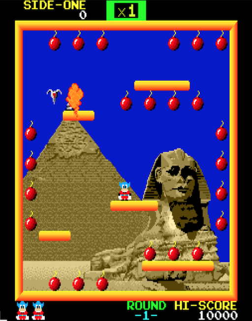
You can explore the emulator version on WebAssembly here:
https://floooh.github.io/tiny8bit/bombjack.html
After the download procedure is complete and the high score table appears, press 1 to drop a coin and then Enter (or any other key except arrows) and a space) to start the game.
Inside the game, use the arrow keys to change the direction and the spacebar to jump. While in the air, press the spacebar to reduce the speed of the fall.
The source code is here:
https://github.com/floooh/chips-test/blob/master/examples/sokol/bombjack.c
It uses chip headersto provide emulation of Z80 and AY-3-8910, as well as sokol headers as a cross-platform wrapper (for entering the application, rendering, input and sound).
Step 1: research
"Research" is too loud a word: I just drove into Google "Bombjack arcade hardware specs".
Compared to the popular home computers of the 80s (or even the mysterious East European computers, which often still have active communities), there is very little information on the Internet about Bomb Jack.
I found two very important pieces of information: the circuit diagram of the automaton and, of course, the source code of the MAME emulator .
There is also a project that implements Bomb Jack on FGPA , from the VHDL source code of which I was able to find out the details missing in the conceptual diagram.
Understanding the source code for MAME would be complicated, because arcade-machine emulators are usually just a bunch of macros describing how different pieces of equipment interact, but the source code itself is not so much.
Nevertheless, the macro descriptions of the equipment, and especially the comments, still proved to be very useful for understanding the work of the hardware, and where they became too mysterious (for example, the video decoding part ), the trial and error method was sufficient, and detailed study of the concept.
Equipment overview
The most interesting thing about Bomb Jack hardware is that there are actually two computers connected to each other with electrical tape: there is a main board with a Z80 CPU and equipment for video decoding and a separate sound card with its own Z80 CPU and three (yes, three!) sound chips AY-3-8910.
Video decoding equipment is not implemented as an integrated circuit - it’s just a multitude of small general-purpose chips (their layout takes 6 out of 10 pages of a device’s schematic diagram). When creating an emulator, I decided to go a short way: instead of emulating individual parts of video decoding equipment, I emulated only its behavior, creating corresponding output from the input data and not particularly worrying about how the equipment itself works in the middle.
Such a simplified solution is quite suitable for a separate arcade machine, which is designed to run only one program. If the game starts and works correctly, then the emulation can be considered “quite good”.
In addition, this simplified approach is an important difference from the emulation of most home computers: some games require more accurate emulation than others, for example, machines such as the C64 or Amstrad CPC need very accurate emulation up to clock cycles, some video games and graphics The demo worked correctly.
It also means that my ready-made emulators of the CPU and sound chip are in fact unnecessary work for the Bomb Jack, for example, the work of the Z80 CPU with the implementation of a fraction of the computer cycle is a brute force, it would be simpler and quicker at the instruction level.
Main board
Usually the first thing I try to figure out when writing a new emulator is the memory allocation scheme (where the ROM and RAM, video memory and special addresses or I / O ports are located).
On the Bomb Jack main board there is only one “interesting” chip - the Z80 CPU operating at 4 MHz. All the remaining space of the main board is occupied by the video decoding equipment (with the exception of a pair of RAM chips and ROM).
The 16-bit address space looks like this:
- 0000..7FFF : 32 KB ROM
- 8000..8FFF : 4 KB of general purpose RAM
- 9000..93FF : 1 Kbytes of video memory
- 9400..97FF : 1 KB color RAM
- 9820..987F : 96 bytes of sprite RAM
- 9C00..9CFF : 256 bytes of RAM color palette
- 9E00, B000..B005, B800 : I / O Ports
- C000..DFFF : 8 KB ROM
The area of I / O ports is as follows. Some ports are write-only, some are read-only, and some have different functions when reading and writing to them:
- 9E00 : write: current background image number, read: -
- B000 : Read: Player Joystick Status 1, Write: Enable / Disable the NMI Mask
- B001 : Read: Player 2 Joystick Status, Write: -
- B002 : reading: coins and Start buttons, writing: -
- B003 : Read: Watchdog CPU, Write: ???
- B004 : read: dip switches 1, write: switch screen
- B005 : Read: Dip Switches 2, Write: -
- B800 : write: command sound card, read: -
Here it is worth mentioning the following:
- The device has MANY ROMs (40 Kbytes), and very little RAM (about 7 Kbytes, and only 4 Kbytes of which are “General Purpose RAM”)
- For “Display RAM”, only 2 KB were allocated, divided into two fragments of 1 KB, which seems very small for a 256x256 full-color display, in which, it seems, colors are set pixel-by-pixel
- This is a system with I / O in the memory allocation scheme!
The I / O in the memory allocation scheme is a bit unusual for a machine with a Z80, because one of the distinguishing features of the Z80 is a separate 16-bit address space for device I / O. This is done to save precious memory address space. I / O in the memory allocation scheme is usually inherent in computers with a 6502 processor.
A glance at the circuit diagram confirms this: the IORQ contact is not detected by the CPU of the main board, only the MREQ contact is connected (which is used to initialize reading or writing to memory):
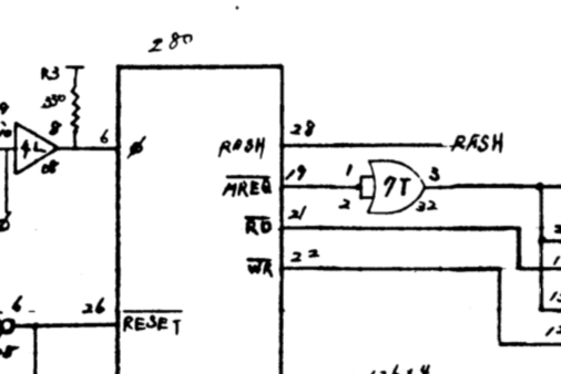
This means that we don’t have to worry about the I / O requests of the CPU timer function of the main board in the emulator, but only deal with memory requests.
After studying the circuit diagram, I found another interesting detail about the CPU of the main board:
Only the NMI contact is connected, while the INT contact always maintains a high level of the clock signal / it remains inactive (this means that the “normal” masked interrupts are not performed, and only non-maskable occur):
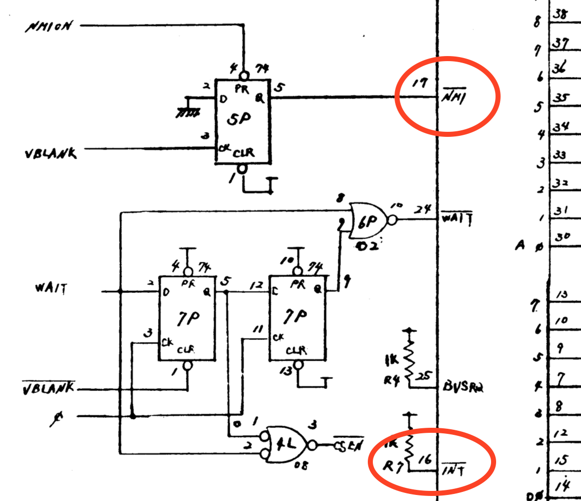
This is also quite unusual for a car with a Z80. In all home computers based on the Z80, with which I had previously dealt, everything was the opposite - they used only masked interrupts, and never used nonmaskable ones. The Z80's masked interrupt is a very flexible and serious improvement compared to the primitive interrupt system of its “illegitimate father” - the Intel 8080, or its competitor - MOS 6502. But this increased flexibility is both more difficult to implement in hardware (unless other Z80 chips are used, which already have a built-in complex interrupt protocol when connected by bus).
Well, okay, enough details about the equipment, go to the emulator!
Download procedure
The next step after determining the memory configuration is to connect the emulated CPU to the emulated memory allocation scheme, record some visualization of the video memory contents and start CPU cycles.
Surprisingly, such a rough approach is often enough to go through the procedure of loading and displaying something on the screen . When developing the Bomb Jack emulator, I simply took the contents of 1 Kbyte video memory in the range from 0x9000 to 0x93FF as a 32x32 byte matrix. When the byte was 0, I rendered a block of 8x8 black pixels, and otherwise a block of white pixels.
Then I just ran the emulated CPU and hoped for the best. Behold There was some legible picture:
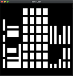
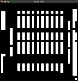
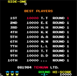
The top image looks like the equipment test screen when loading, and the bottom one looks like the points record screen that appears after the loading procedure is completed:
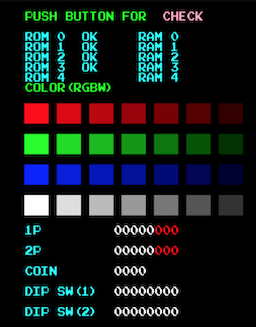
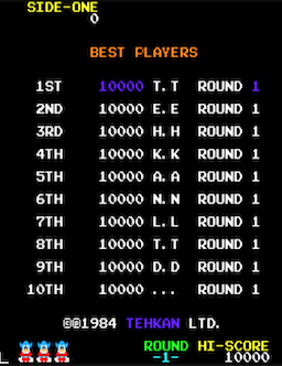
... but rotated 90 degrees (which is logical, because the screen of the arcade automata was often in a vertical “portrait” orientation).
Great, the start is promising!
The next step is to figure out how to turn these white blocks into color pixels ... (and this is a huge step, details are described below in the section on video decoding).
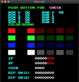
At first everything went pretty fast, pixels and colors were displayed on the test screen (later I noticed that the color decoding was completely wrong, and yet ...):
But when the records screen was to appear, I got a black screen. Hacking the background color so that it was “not black”, I found that the pixels are rendered, but the whole color palette is black. Hmm ...
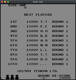
Looking at this screen for a couple of minutes, I remembered that some of the colors on the highscore screen are animated, and when there is animation, there must be some kind of timer. The logical time source in this hardware configuration will be the display's VSYNC signal, and the VSYNC is connected to the NMI pin of the CPU (or, rather, not VSYNC, but VBLANK, which is a brief moment between the VSYNC signal and the ray of the cathode ray tube in the upper left corner).
And I have not yet implemented all this ...
The next night, when I added the first version of NMI processing to the Z80 emulation and connected it to the first vsync / vblank counter in the mainboard CPU timer function, a lot of things suddenly started to happen!
First, the colors appeared on the records screen, and some of them were animated:
After a few seconds, something even more amazing began! The record screen disappeared, and a strange visualization of the first map was displayed. It was clear that this is a demo mode of an arcade machine for attracting attention - I saw several bombs with color animation that disappeared when the imaginary Bomb Jack was jumping around the map, collecting these bombs:
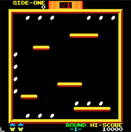
The colors were still completely wrong, and yet it is PROGRESS!
It’s time to do the rest of the video decoding:
Iron Video
At first glance, the Bomb Jack video equipment looked very powerful for an 8-bit machine from 1984: despite the resolution of only 256x256 pixels, it could simultaneously display 128 (out of 4096) colors, and render up to 24 hardware sprites (16x16 in size) or 32x32) with pixel set color.
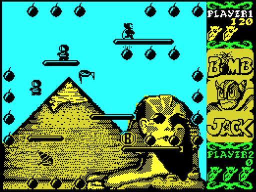
The 8-bit home computers of that time had about the same display resolution, but they had many limitations regarding colors. These limitations are very noticeable when comparing the versions of Bomb Jack for the ZX Spectrum and Amstrad CPC with the version for the arcade machine:
The version for the ZX Spectrum there was a pretty good pixel resolution (256x192), but very few colors, and she suffered from the typical Spectrum effect of “color conflict” (although the developers did their best to make it not too noticeable):
The Amstrad CPC version is more full color, but to get more colors, the developers had to switch to the low resolution display mode (160x200). As a result of this, Jack and the monsters turned into an illegible pile of pixels:
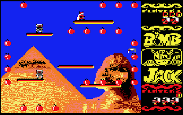
Compare this with the version for the arcade machine, which had the same resolution in pixels as the ZX Spectrum, but with a much larger number of colors and a higher pixel resolution of colors:

The interesting thing is that the arcade version has better graphics, not because it works on a more powerful hardware (it has more ROM for storing more graphics data, but the “computational power” is about the same), but because the device developers could concentrate on the manufacture of specialized machines for one particular type of game and they did not need to create a universal general purpose home computer.
Here's how the display hardware works (at least in my high-level interpretation):
Three layers of display
The finished Bomb Jack video signal is combined from three layers: the background layer, the front layer and the sprites layer.
Such a system of layers has two main advantages:
- It implements a rather tricky hardware image compression to generate a full-color “high resolution” image over a very small amount of data.
- It significantly reduces the amount of CPU work required to update the dynamic elements of the screen (even at 4 MHz, the 8-bit CPU does not have enough power to move such a number of objects across the display 256x256 at 60 Hz)
Video iron is quite different from what I saw in 8-bit home computers, but MAME implements generalized auxiliary classes for this type of equipment, so I can assume that it is quite often found in arcade machines.
Background layer
The background layer can render 1 of 5 background images embedded in ROM. The background image is selected by writing a value from 1 to 5 at 0x9E00 (it looks like the value 0 is special and renders a completely black background).
In fact, it seems that the equipment is capable of rendering 7 different images, but only 5 are used in the game. In secret, I was hoping to find previously undetected image data in the ROM. But alas, they are not there (yes, I probably am not the first to look for them there).
Here is the background layer of the first map without the other two layers:
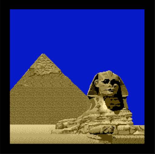
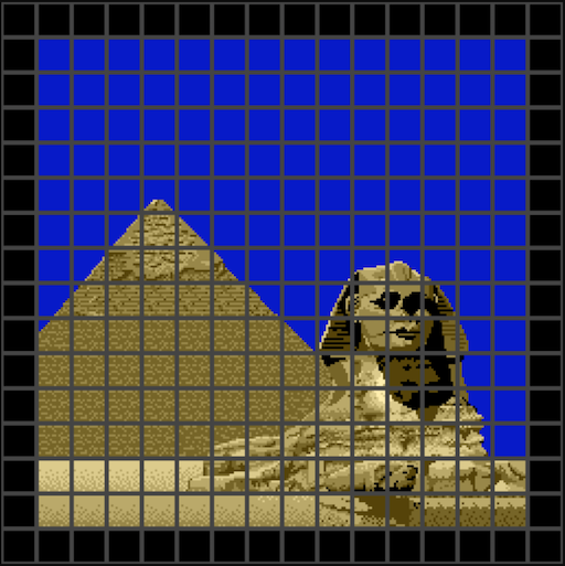
The background layer is made up of 16x16 pixels.
The advantage of building background images from tiles is that identical tiles can be used multiple times, so less data can be stored in the ROM. Notice that the blue sky, parts of the pyramid and the sand under the pyramid use the same tiles:
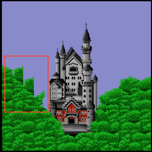
To save memory, the background layer equipment implements one more trick - tiles can be flipped horizontally. I almost missed it in my implementation, because I assumed that the software does not use this hardware function, but noticed a small bug in the background of the third card:
The same trick used on the fifth map, but here it is a little harder to notice if you don’t know what to look for:

Front layer:
Above the background layer is the “front layer”, which renders all the fixed parts of the screen, which nevertheless must be updated by the CPU (mostly text, platforms and bombs). The layout is read from RAM (from 1-Kbyte RAM fragments and 1-Kbyte color RAM).
Here is the isolated front layer of the first map:

The front layer also consists of tiles (as well as background), but it uses smaller tiles of 8x8:
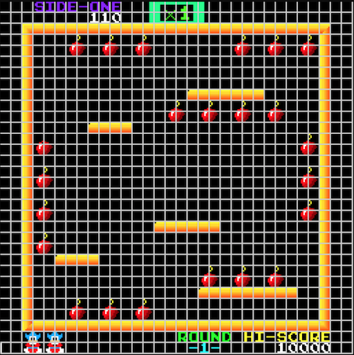
The main advantage of separating the background and the front part into separate layers is that the CPU does not need to worry about storing and recovering background pixels when creating or deleting the front elements.
Sprites layer
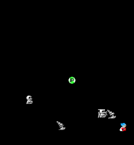
Finally, hardware sprites are rendered on top of the front layer. Everything that moves around the screen is implemented in sprites. Bomb Jack equipment can render up to 24 sprites, and each sprite can be 16x16 or 32x32 pixels. At the same time, sprites can be positioned with pixel precision:
8x8 tile decoder
In the “heart” of the video decoding equipment there is a color palette with 128 elements and a tile decoder 8x8 pixels in size. The task of the tile decoder is to generate a 7-bit color palette index for each of the 64 pixels of the tile.
These 8x8 tiles are the building blocks for everything on the screen — 16x16 background tiles, 8x8 front-layer tiles, and 16x16 or 32x32 hardware sprites.
Here is the block diagram of this 8x8 tile decoder for rendering the front layer (as I understood it):
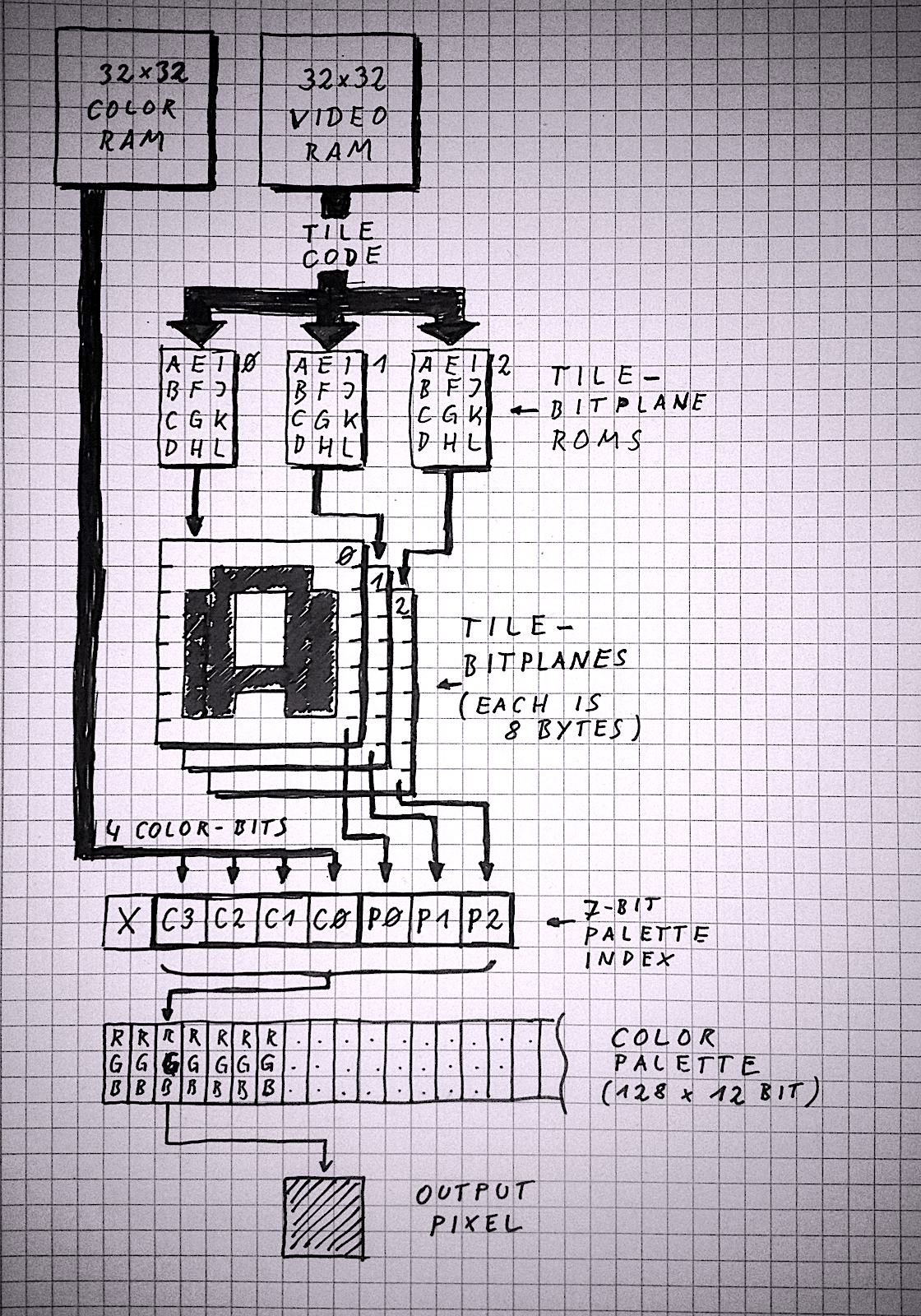
Top-down flowchart explanation:
- The decoding process begins at the top with reading a byte of the “tile code” from the video memory (organized as a matrix of 32x32 tile codes) and a separate byte from the color RAM (also a 32x32 matrix). Getting tile codes and colors from video memory only happens for the front layer, but I added it so that the picture as a whole is clearer. The 8x8 tile decoder itself only needs a tile code and colors at the input.
- The tile code is used as an index for searching in three separate pixel bit layers. These pixel bit layers are always stored in ROM (pixel bit layers can be thought of as font data or sprite shits). Each of the three layers of the display has its own ROM of tiles, and these ROMs are visible only to the decoding equipment, but not the CPU (so that they do not occupy the precious address space of the CPU).
- Each pixel bit layer consists of 8 bytes per tile, and each byte contains 8 pixels (one bit per pixel). Since pixel data for each tile is collected from three bit layers, this means that to describe the appearance of an 8x8 tile, 24 bytes of ROM data are required (3 bits per pixel).
- For each of the 64 pixels of the tile, a 7-bit value is created. The lower 3 bits are taken from the bit layers of tiles from the ROM of tiles, and the upper 4 bits from the byte of the color value. In essence, this means that each tile can choose one of 16 “slots” in the color palette, where each slot contains 8 colors. Each pixel of the tile can choose one of 8 colors in the slot of the tile palette.
- This 7-bit index, compiled from bit layers and tile color values, is used to search for a 12-bit RGB color value from a color palette (4 bits per color channel). The color palette is located in the RAM and the CPU can work with it (as far as I have seen, the video RAM, colors and palettes are used only for writing; at least, the CPU never has read access to these areas).
This is a general tile decoding scheme that is used by each of the three layers of the display, but the decoding of each layer is slightly different:
- The front layer can actually render 512 different 8x8 tiles. This requires 9-bit tile codes, but the video memory only provides 8 bits per tile. The ninth bit is “borrowed” from the fifth bit of the color value (since only 4 bits of the color value are used to build the color palette index, 4 more bits are left for other purposes). If all 3 bits of the 8x8 bit layers of the tile are zero, then the front pixel is considered transparent, and the background pixel shines through it.
- 16x16 tiles are used in the background layer, so it needs only 16x16 = 256 tile code values and 256 color values to describe the background image in the background image ROM (512 bytes per image). The trick here is that the 16x16 pixel bit layers are built in four 8x8 tiles, so you can use the same decoding hardware. As mentioned above, the background tiles can be mirrored horizontally; This operation is controlled by one of the “spare” bits of color values: if bit 7 of the color value is set, the tile will be mirrored.
- Each hardware sprite can be 16x16 pixels or 32x32 pixels in size, and bit layers also consist of 4 or 16 consecutive 8x8 tiles in the sprite tile ROM. This means that a 16x16 sprite requires 96 bytes, and a 32x32 sprite requires a monstrous volume of 384 bytes in the ROM of the tiles. As in the case of front tiles, if all 3 bits of the pixel bit layer are zero, then the sprite pixel is transparent.
To better understand how the bit layers of tiles look like, I wrote a small C program that converts tile ROMs into PNG files (3 bits per pixel are converted to 8 levels of shades of gray).
Below is the front layer tile ROM. We see numbers and text font data, platform tiles, bombs (split in half), parts of the logo from the Bomb Jack screensaver, and the number of points multipliers that appear at the top of the screen (by the way, everything is rotated 90 degrees because the whole screen is also rotated ):

Next, consider the background tile rom. It doesn’t look very clear, because what we are seeing is actually decoding 16x16 tiles into 8x8 tiles. Each 16x16 tile is made up of four adjacent 8x8 tiles. But you can recognize parts of the Greek temple from card 2, castle from card 3 and skyscrapers from card 4.
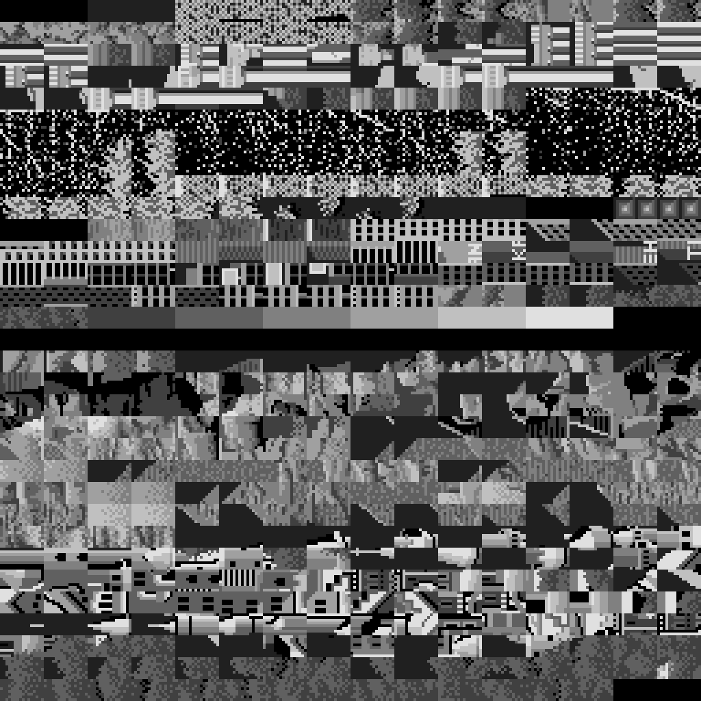
And finally, the sprite tile rom. Sprites 16x16 occupy the upper half, and sprites 32x32 - the bottom.

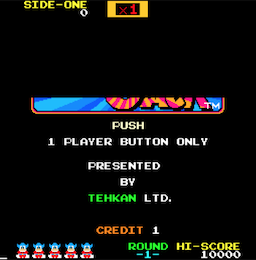
An interesting hack of the Bomb Jack screen saver is that the logo is assembled from front tiles and sprites. I think that the developers ended the front tile ROM, but there was still a bit of space in the sprite ROM:


Sprite equipment
Bomb Jack sprite hardware is very powerful compared to that used in home computers of the time:
- It could render up to 24 hardware sprites. It seems that there were no restrictions on the number of sprites per scan line.
- Sprites could be 16x16 pixels or 32x32 pixels.
- Each sprite could choose from 16 slots of 8 colors in a common color palette.
- Sprites had per pixel color resolution.
- Each sprite could be turned vertically or horizontally.
- Each sprite could choose one of 128 sprite images stitched in ROM.
When decoding pixels and sprites of a sprite system, the same 8x8 base tile is used as in the background and front layers.
Attributes of sprites are located in the address range from 0x9820 to 0x987F - 96 bytes, 4 bytes per sprite. As far as I saw, this area is write-only; at least, the CPU does not perform read access to this memory range.
Each sprite is described by 4 bytes:
- Byte 0 :
- Bit 7 : if set, this is a 32x32 sprite, otherwise 16x16
- Bits 6..0 : 7 bits for setting the code of the sprite tile used to search for the bit layers of the sprite image in the ROM of the tiles.
- Byte 1 :
- Bit 7 : if set, then the sprite is mirrored horizontally
- Bit 6 : if set, the sprite is mirrored vertically
- Bits 3..0 : 4 bits to set the color value for the tile decoder
- Byte 2 : sprite position on the screen on the X axis
- Byte 3 : sprite position on the screen on the Y axis.
It is not clear what bits 4 and 5 of byte 1 do; the comment in MAME says this:
 e ? (задаётся, когда выбираются большие спрайты)

 f ? (задаётся, только когда материализуется бонус (B)?)
Memory I / O ports
A few notes on the I / O ports of the main board. As stated above, I / O ports look like this:
- 9E00 : write: current background image number, read: -
- B000 : Read: Player Joystick Status 1, Write: Enable / Disable the NMI Mask
- B001 : Read: Player 2 Joystick Status, Write: -
- B002 : reading: coins and Start buttons, writing: -
- B003 : Read: Watchdog CPU, Write: ???
- B004 : read: dip switches 1, write: switch screen
- B005 : Read: Dip Switches 2, Write: -
- B800 : write: command sound card, read: -
We already considered the address 0x9E00 (the choice of the background image) above, and the address 0xB800 (the sound card command) we will consider in the next section. The addresses from 0xB000 to 0xB005 remain:
Reading from addresses 0xB000 and 0xB001 returns the current state of two joysticks. Specified bytes indicate closed joystick switches:
- bit 0 : direction "right"
- bit 1 : direction "left"
- bit 2 : direction "up"
- bit 3 : direction "down"
- bit 4 : jump button is pressed
The remaining 3 bits are ignored.
Reading from 0xB002 returns the status of the coin acceptor and the Start buttons:
- bit 0 : player 1 coin inserted
- bit 1 : player 2 coin in
- bit 2 : player 1 start button
- bit 3 : player 2 start button
Reading from addresses 0xB004 and 0xB005 returns the state of the dip switches, which are used to configure the behavior of the arcade machine:
- B004 :
- bits 0,1 : how many "games" are given for one coin (1, 2, 3 or 5)
- bits 2.3 : same for player 2
- bits 4,5 : how many lives per game (3, 4, 5 or 2)
- bit 6 : location of the arcade machine: “cocktail table” or “vertical”.
- bit 7 : whether to play sound in standby mode
- B005 :
- bits 3,4 : difficulty 1 (bird speed)
- bits 5.6 : difficulty 2 (the number and speed of enemies)
- bit 7 : the frequency of occurrence of a special coin
Finally, reading from address B003 implements a software watchdog timer. The CPU should often read from this address, otherwise the arcade machine will perform a hardware reset. If for some reason the game fails, the equipment will automatically reboot.
You can write to some I / O port addresses:
- B000 : Do I need to generate NMI during vblank; seems to be disabled only during the boot procedure
- B004 : flip the entire screen; I have never met the use of this function, but I have a theory about it (see below)
The screen flip function is a bit confusing, because when playing a game, I have never seen its use. However, I have a hunch about what he is doing, but to confirm it, you need to write code. When the arcade machine is in the "cocktail table" configuration, two players are seated opposite each other. Therefore, I assumed that when a game switches from player 1 to player 2, this function reverses the screen. However, I have not yet implemented the two-player mode in the emulator.
Sound card
The sound card itself is a full-featured computer with a Z80 CPU (running at 3 MHz), three sound chips (AY-38910 running at 1.5 MHz), as well as RAM and ROM. The sound card memory distribution scheme looks pretty simple:
- 0000..2000 : 8 Kbyte ROM
- 4000..4400 : 1 Kbyte of RAM
- 6000 : sound command from the main board
Since there is nothing interesting about the above address 0x8000 in the memory allocation scheme, the top-most address contact of the CPU is not even connected:
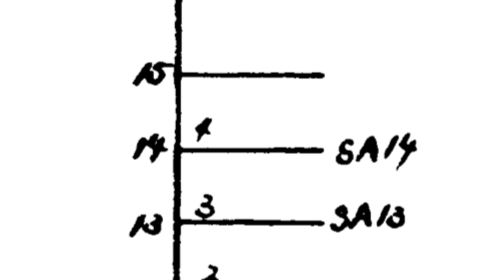
The special address 0x6000 is the memory-mapped I / O port (8-bit latch) that does not correspond to the real RAM. This is the same port that is located on the main board at 0xB800. It is the communication channel between the main and sound cards.
The three sound chips are controlled by these Z80 output instructions, and not through the ports in memory. At AY-3-8910, only two I / O ports are open, the first is used to store the register number, and the second is for writing or reading the contents of the register specified by the first port.
The I / O scheme is as follows:
- 0x00 : first sound chip: register selection
- 0x01 : first sound chip: access to the selected register
- 0x10 : second sound chip: register selection
- 0x11 : second sound chip: access to the selected register
- 0x80 : third sound chip: register selection
- 0x81 : the third sound chip: access to the selected register
AY-3-8910:
This is a fairly standard device, very popular in home computers of that time (for example, in Amstrad CPC, ZX Spectrum 128, in MSX computers and many others). AY-3-8910 spawned many variations and clones (for example, the Yamaha YM2149, which itself became the basis of a whole family of more powerful sound chips).
AY-3-8910 has 3 channels of rectangular signals, one noise generator that can be mixed with three channels, and one envelope generator. Since there was only one envelope generator for all three channels, it was not particularly useful, and most games used the CPU to modulate tone and volume.
This means that the AY-3-8910 chip to create high-quality sound requires more CPU intervention (as opposed to more autonomous SID chips, for example, in the C64 computer).
It's amazing to see what can be done on three fairly simple sound chips and the CPU that controls them. The music and sound effects of Bomb Jack are much richer than I had heard in most games for home computers.
The only thing that is really interesting in this sound card is the way it receives its commands from the main board.
Sound command latch
“Sound Latch” is a single-byte storage (8-bit latch), common to the main and sound cards. The latch is tied to the address 0xB800 on the main board and to the address 0x6000 on the sound card.
When enabled with VSYNC NMI interrupts, the sound card performs a very simple interrupt service routine that reads the hardware latch, writes it to the usual memory address and sets a “signal bit” that tells the “main loop” that a new sound command has been received:
        ex af,af'               ;0066
        exx                     ;0067
        ld hl,04390h            ;0068
        set 0,(hl)              ;006b
        ld a,(06000h)           ;006d
        ld (04391h),a           ;0070
        exx                     ;0073
        ex af,af'               ;0074
        retn                    ;0075
The method of activating the NMI contact is slightly different from the method for the main board:
On the main board, the NMI contact becomes active during the execution of VBLANK.
However, on the sound card, the NMI is activated when VSYNC is triggered, and remains active not during VBLANK, but until the interrupt service routine does not read the data from the latch at address 0x6000.
When the equipment recognizes reading from the address 0x6000, it performs two hard-coded operations:
- the sound of the latch is reset to 0
- NMI contact becomes inactive
In fact, this is a simple debugging of contacts, which does not allow one sound command to be performed twice.
The only question left is how often the main board records a new command (because the way to implement the emulation of the two boards depends on this).
After debugging with printf, I found that the main board records no more than one sound command per 60 Hz frame. This greatly simplified the structure of the “main loop” of the emulator.
The problem of the joint work of two separate emulated computers that need to exchange data with each other is that the emulation of one computer is effective only if it can perform many cycles at once without interference.
For example, the worst case would be:
- we execute in the computer 1 one instruction
- we execute in computer 2 one instruction
- repeat ...
My Z80 emulator is not optimized for entering and entering the emulation for each instruction, because in this case it should reset the memory and load CPU state at the beginning and end of each instruction into memory. If the CPU can process many instructions without interference, then it is possible to store (most of) the state of the CPU in registers and reset the state to memory on the last instruction.
That is, the ideal situation would be this: run the emulated system without interference during the entire frame of the host system (for a CPU with a frequency of 4 MHz and at 60 Hz, this means about 67 thousand cycles per frame, or anywhere from 3 thousand to 16 thousand instructions Z80).
When working with Bomb Jack, I needed to make sure that the main board did not record the new command before the sound card could be able to read the last command. Before I found out that the main board records no more than one command per frame, I considered the need to create a complex command queue that would intercept recordings into the sound latch of the main board and store the cycle number and command byte in the queue.
Then, when the sound card was performing its frame, it would take a new command from the command queue when the command cycle number was reached.
Such a system would work and would be “correct”, but would greatly increase the complexity of the code.
In the end, I decided to use a much simpler solution without any queues. Since the main board records only one command per frame, I alternated execution on two computers so that each of them performed two time slices per frame:
- perform on the main board the first half of the frame
- perform the first half of the frame on the sound card
- perform the second half of the frame on the main board
- perform the second half of the frame on the sound card
This ensures that the sound card correctly sees each command recorded by the main board, and at the same time will be able to perform each emulation for thousands of cycles.
Of course, the fact that the host system operates at approximately a frame rate of 60 Hz is a very bold assumption :)
And the last ...
The last interesting fact about the version of the emulator on WebAssembly: The
compressed size of all downloaded files when running the emulator on WebAssembly is
approximately 113 KB:
- about 2.5 KB in HTML, CSS, and handwritten JS
- 26.8 KB per file emscripten runtime JS
- 83.7 KB per file .wasm
The WASM file contains the embedded ROM of the arcade machine.
In uncompressed form, these ROMs occupy 112 KB.
That is, the entire compressed emulator with embedded ROM occupies almost the same volume as the uncompressed ROM :)
112 KB ROM is compressed to about 57 KB, that is, the true size of the compressed code in WASM without ROM data takes less than 30 KB (84 - 57) .
It seems to me, not bad at all for a full 8-bit system emulator;)
