Training Cisco 200-125 CCNA v3.0. Cisco Certified Network Specialist (CCNA). Day 2. OSI and TCP-IP models
- Transfer
- Tutorial
From the previous video, we learned about the basics of the network, and today we'll talk about the OSI model and the TCP / IP model. When I say models, I mean nothing more than a set of rules, or a set of standards. You may ask why we need a set of rules or standards in the computer industry? To understand this, we need to learn a little about the history of the computer industry.
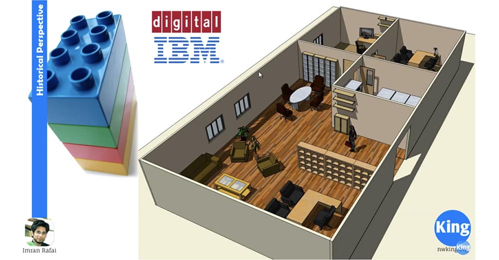
Not so long ago, a fierce battle took place between IBM and Digital Equipment Corporation (DEC) over who is the leading manufacturer of computers. But there was a problem. Both of these manufacturers produced computer equipment that was incompatible with each other. That is, if you bought an IBM computer, then you had to purchase a monitor for it, a printer and everything else from IBM too. Similarly, if you bought a device from DEC, then you had to buy all the accessories and other devices from the same manufacturer so that they can be used.
There were many companies that bought equipment from both manufacturers, so that, for example, there were IBM computers in accounting, and the marketing department was equipped with DEC computers. As a result, these devices could neither communicate nor share information with each other. Thus, the lack of a unified standard did not allow computer technology to move forward. This happened around the time when the International Standards Organization, known as ISO, came to the conclusion that there was a need for a common computer standard. ISO developed OSI - Open System Interconnect, or the OSI reference model. At about the same time, a competing standard was created - the TCP / IP model, the appearance of which was facilitated by the Ministry of Defense. The TCP / IP model is more like a stripped-down version of the OSI model and, due to its greater relevance, has become the industry standard. To get the concept of models, it is necessary to consider the concept of "stack level". Let's consider it on the example of the office shown in the picture. Each office has different levels of employees: CEO, senior office staff, salary manager, account manager, service manager, support staff, and junior office staff are all different employees. The reason why each company has different employees with different job titles is due to the fact that they perform different duties and have different levels of responsibility. Let's consider it on the example of the office shown in the picture. Each office has different levels of employees: CEO, senior office staff, salary manager, account manager, service manager, support staff, and junior office staff are all different employees. The reason why each company has different employees with different job titles is due to the fact that they perform different duties and have different levels of responsibility. Let's consider it on the example of the office shown in the picture. Each office has different levels of employees: CEO, senior office staff, salary manager, account manager, service manager, support staff, and junior office staff are all different employees. The reason why each company has different employees with different job titles is due to the fact that they perform different duties and have different levels of responsibility.
Therefore, when something is not done or a specific task is not completed, you know who is responsible for it. For example, if a salary is not paid on time, then the salary manager is responsible for this. No matter what the bank may be to blame for, the first contact you use to clarify the issue is the payroll manager. If your office is not cleaned, then this is responsible economic department. That is, the job hierarchy allows you to distribute responsibility.
Similarly, we need to have knowledge of the OSI model and the TCP / IP model, because when studying computer networks or when problems arise in them, we need to know what works at what level. Because in the event of a malfunction, we will not need to check all the equipment, as using the level approach, we will know exactly what could be the problem.
Let us go directly to the models to figure out how they work and what levels are involved in this. Let's compare both models.
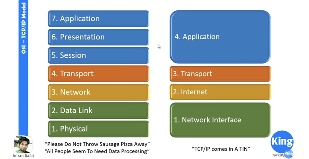
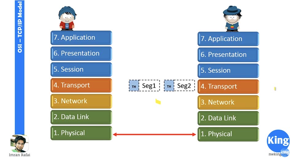
On the left you see the levels of the OSI model, on the right - TCP / IP. Let me take the marker to make it clearer. I marked the levels with different colors, so you won’t get confused. Let's start the discussion on the left, with the OSI model. Before we go further, I will emphasize that as networker students, you should know all these levels and their location by heart!
You need to know that level 7 is the application level, level 6 is the presentation level, level 5 is the session level. You need to know where these levels are! One way to memorize a sequence of levels is to use mnemonics. One of the most popular phrases for memorizing OSI levels is Physical, Data link, Network, Transport, Session, Presentation, Application, from bottom to top, like this: Please, Do Not Throw Sausage Pizza Away (Please do not throw away the pizza with sausage)!
If you want to memorize the layout of the levels from top to bottom, use the phrase All People Seem To Need Data Processing (It seems that all people need data processing).
In the way of memorization - from top to bottom or from bottom to top - the choice is yours, you just have to remember that 1 level is physical, and 7 is applied. Some people are confused, believing that the levels go on increasing from top to bottom, and level 1 is applied. It is not, the first level is physical, and the applied level is level 7.
If you want to remember the location of the levels of the TCP / IP model, use the "TCP / IP comes in A TIN" mnemonic. It means nothing, you just need to remember A TIN - Application, Transport, Internet, Network. If you have a better way to memorize, use it until you firmly learn these sequences.
Let's start with the application layer. The application layer is the point of contact for all network applications, a common point of contact. Many authors say and write that all applications on your computer are at this application level, which is not true. First, the application layer only applies to network applications, and secondly, any applications on your computer have nothing to do with the application layer if they do not communicate over the network.
To make it easier for you to understand, I will give a simple example. Suppose that you have removed Wi-Fi and Bluetooth wireless interface drivers, Ethernet network card drivers from your PC, or even physically removed these devices. So, if you now run, for example, Microsoft Word, it will not be able to communicate with the application level and because of this it will not be able to communicate with any other level. This is because Microsoft cannot access the network, because your operating system does not even have a network card!
Similarly, in a regular system, if you launch a web browser, for example, Chrome, IE, Safari and type something like www.cnn.com in the address bar, the web browser will create an http request that interacts with the application layer. The application layer transmits this data to the presentation level (often erroneously called the representative level), the presentation level transmits it to the session level, that is to the transport level and so on until the data reaches the physical level. Here is how it works.
Thus, if an application interacts with networks, then this happens only through the application layer. This level provides access to network services. The FTP, TFTP, SNMP, DNS, HTTP protocols work at this level, there are quite a lot of them. You can simply “google” a complete list of all the protocols running at this level!
Next we look at the presentation level. This level performs data presentation and encryption. The presentation layer is where all the data conversion takes place, it is responsible for encoding the data, that is, after it the data for other levels become the same, regardless of whether it is a picture or a document. Then it takes the data arriving on the way back from the session level, converts it into a presentable form and transmits it to the application level. Therefore, if you have raw data coming from the session level, they are converted at the presentation level. If this is an image, the level creates an image; if it is a Word document, it creates a Word document. In addition, all encryption services, such as TLS and SSL, work at this level.
Next we have a session level that creates and maintains data transfer sessions. Suppose that your computer starts two applications — Telnet and IE. Both of these applications gain access to the network. Therefore, this level creates 2 different sessions and supports them. Thus, when a web browser session is terminated, the Telnet session will not terminate because they are separate sessions. That is, this level supports different sessions.
You can see that the top three levels 5,6,7 of the OSI model and level 4 of the TCP / IP model are marked with the same blue color. As a network engineer, especially a Cisco network engineer, I did this for the reason that we very rarely turn to levels 5,6,7. This is due to the fact that most Cisco devices do not look beyond Level 4. Levels 1, 2, 3, and 4 are very important to a Cisco engineer, and levels 5,6,7 are not so critical. You just need to know how it works, and you basically learned what these top three levels do. The fact is that the operating system basically takes care of them, but as for the work of levels 1, 2, 3 and 4, you as a network engineer should know absolutely everything.
We now turn to the consideration of the transport level. This level is also important for the network engineer. When the information coming from above arrives at the transport level, it breaks up the data into manageable segments, and on the way back it collects them from the segments again. To create encapsulation, the transport layer adds its own header to each segment.
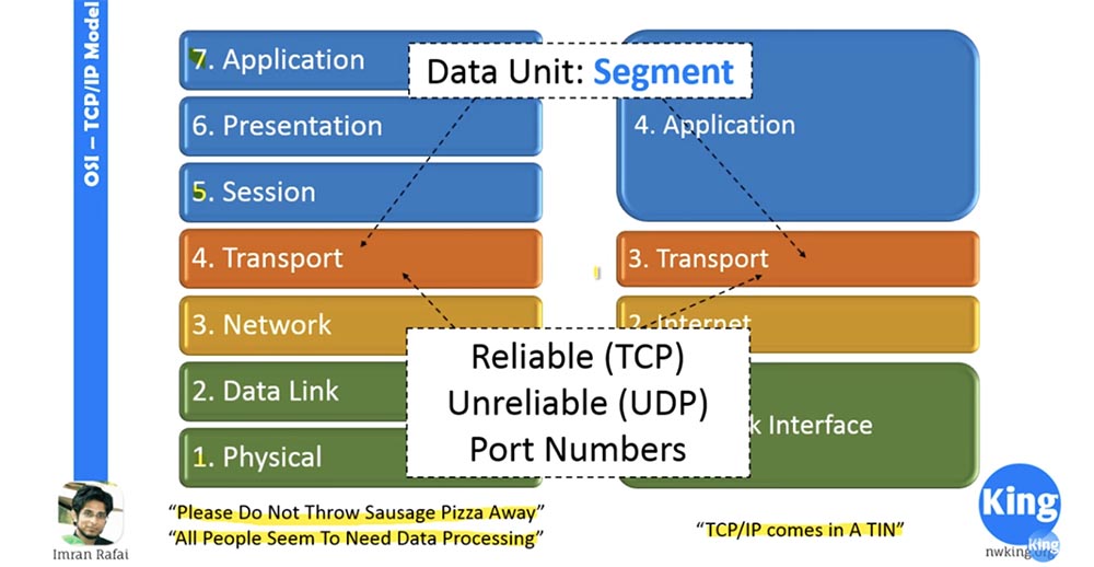
The transport layer makes two important decisions: use a trusted (TCP) or untrusted (UDP) connection, and creates port numbers. When applications need to use a trusted connection, TCP is the transmission control protocol. If an untrusted connection is allowed, the transport layer uses the UDP (User Datagram Protocol). When I say "trusted", it does not mean that it is better than "untrusted", the only difference between them is that when you install a trusted connection, you must receive confirmation for each package sent. In an untrusted connection, you do not need to acknowledge receipt of each transmission segment, so it works faster due to lower overhead. So, if we have real-time applications, they will use UDP, because it is faster and it happens in real time. If you watched streaming video or live online broadcast, sometimes green pixels appear on the screen. This means that information for this image segment, or this pixel, was not received, and the receiving device has no way of informing the sending device.
The second function that the transport layer takes care of is the creation of port numbers. A port number is a number that is attached to an IP address to determine which process information comes from. The transport layer creates a random port number of the source (the sending process) and appends the port number of the destination (recipient). So if your traffic arrives at the server, then the server has the standard port number 80. If you are going to send data to the IP address 10.10.10.10, then the transport layer adds port 80 to this address, which creates a socket 10.10.10.10. 80, which is nothing more than an IP address and port number.
The transport layer creates a socket and sends it below the network layer. It also adds the source port number. Why do you need this number? The reason is that if there are 2 applications running on the computer, and the data comes to the same IP address, the transport layer needs to know what data is being transferred to which application. It will determine this by the source port number.
Next we look at the network layer. When the network layer receives a segment from the transport layer, it adds a network layer header to it. Adding a header turns a segment into a package.
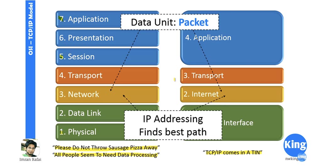
Thus, one of the most important functions of the network layer is the translation of physical IP addresses into logical addresses, that is, logical addressing. We will learn about it in the next video “Day 3”. For now, just remember that the network layer is the level at which IP addresses are added and the optimal path for data transfer is selected. The best path means that the network layer compares IP addresses and checks whether the destination IP address is on the local subnet. If it is not on the local subnet, then the level will find the best path to the destination.
Next we have the link level. When a packet arrives from the network, the link layer adds a channel header to it. As a result, the package turns into a frame. The link layer is responsible for MAC addressing. A MAC is nothing more than an acronym for Media Access Control, and a MAC address is a hardware address.
This means that each network card on your computer has its own MAC address. It is also known as Burn-in-Address, which cannot be changed. There are software ways to spoof an address, but it is physically impossible to change it.
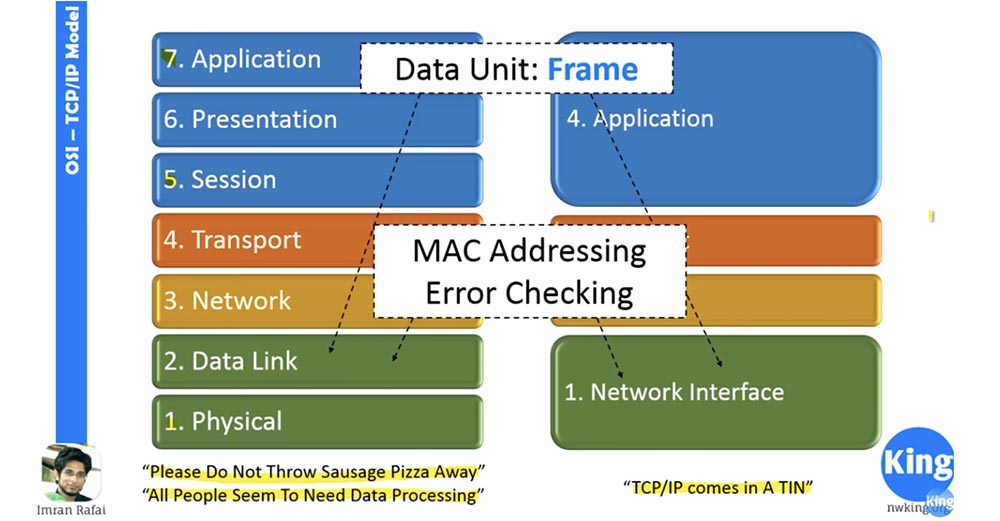
This is the level at which error checking occurs. Therefore, when information comes from the physical layer, the link layer checks it for errors that occurred during the transfer process and corrects them. It can use cyclic redundancy checking — a CRC checksum calculation algorithm, parity check, or any other error checking mechanism.
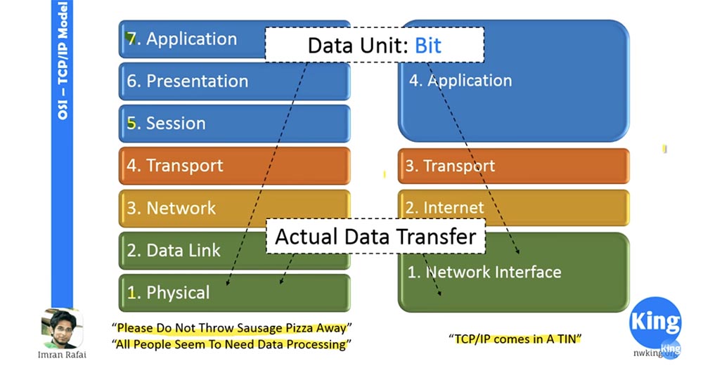
Then follows the physical layer, where data is actually transmitted. Here the data is in the form of bits. This layer deals with wires, cables, hardware ports or connectors, and the like, which ensure the processes taking place at this level. When someone tells you that the Internet does not work for him, you, as a computer or network engineer, start working with physical troubleshooting. First of all, you will check all the connectors and cables, and if they are in order, you will proceed to troubleshoot at 2,3,4 levels. That is why we need to know about network models and remember that any change at one of the levels will not affect the neighboring ones, because this is provided for by the standard.
Therefore, if I prefer to use a wireless connection at the physical level instead of the LAN cable, this should not affect the other levels at all, because the change occurred only at the physical level. Thus, while at the physical level information is received in the normal mode, the method of obtaining this information does not matter.
Similarly, it happens at the network level. We are now in the midst of a transitional phase from IPv4 to IPv6, so this change only applies to level three. Layer 4 and layer 2 will not be affected by this, as long as the existing standard is respected and they receive data in the same way as before.
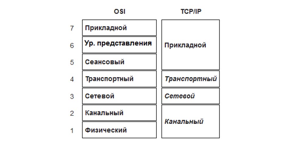
Such is the beauty of a multi-level approach to networking. If you compare the left and right half of the figure, you can see that level 5,6,7 of the OSI model is comparable to level 4 of the TCP / IP model. The transport layer performs similar functions in both models, a similar correspondence occurs at levels 2 and 3, and levels 1 and 2 of the OSI model in their functions correspond to level 1 of the TCP / IP model.
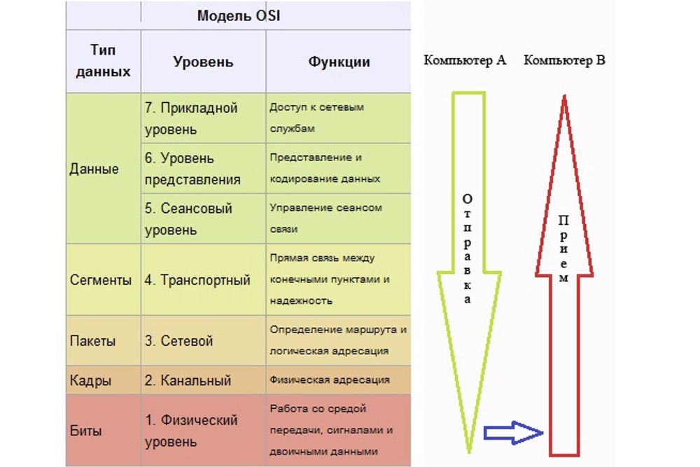
Next, we look at how the OSI model works. Let's say the little man on the left is going to send information to the right little man and for this creates data. Since we have agreed that the top three levels 5.6 and 7 are not of particular interest to us, let us proceed immediately to level 4 of the transport, where our data arrive.
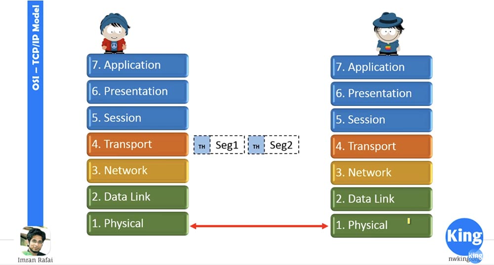
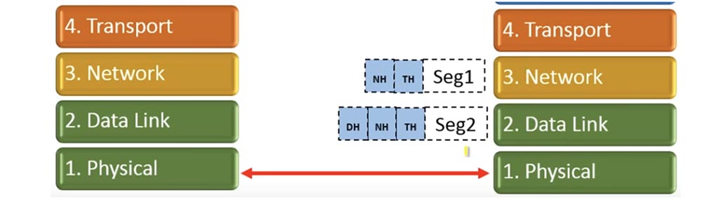
The transport layer accepts data, segments it and adds its own header — you can see it in the figure. Suppose we are dealing with UDP here, so he does not wait for confirmations. It sends segment 1 to the network layer, it adds a network header to the segment, and now it becomes a packet.
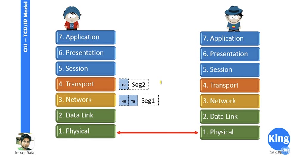
Next, the network layer sends this packet 1 to the data link layer. He accepts the packet and provides it with a Data Link header.
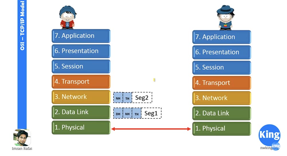
As you can see, the same procedure applies to segment 2. Then segment 1 goes to the physical communication layer, which converts it into a sequence of bits and sends it to the physical layer of our addressee.
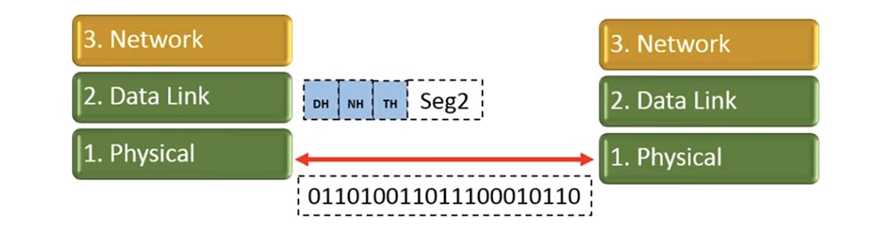
So, our segment 1 has been converted, and the second segment will also be converted into a sequence of bits. By that time, the right physical layer will already accept the previous segment as physical bits and convert it to a segment with a corresponding set of headers.
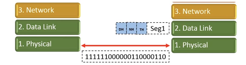
Receiving levels at each step cut off the corresponding header and transmit the segment above. Thus, when segment 1 switches from the link layer to the network layer, it will lose the link layer header.
Similarly, it will happen with the second segment. When segment 1 reaches the transport layer, the network header will be removed. Further, the transport layer will wait until it receives all the transmitted segments.
This is what the transport level does - it waits for the 2nd segment to reach it.
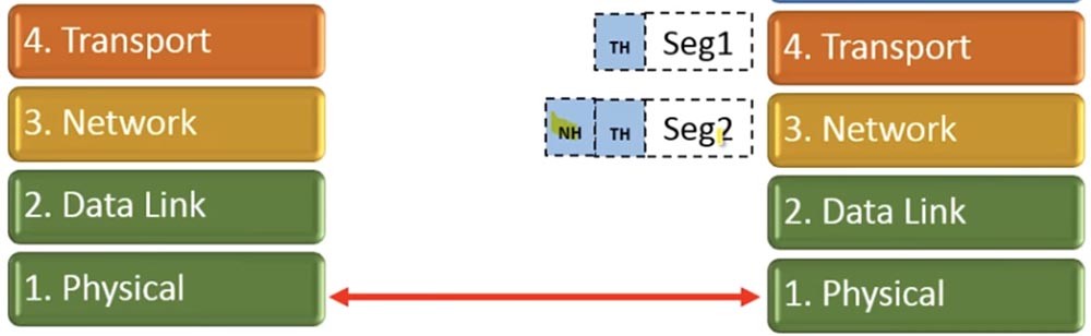
After that, the transport layer will delete all its headers, merge the segments into an array of data and transmit the data to the upper levels, and the right little man will receive exactly the same data that the left little man sent him.

This is a generalized representation of how data transfer over the network works. That's all we had to learn in the second video tutorial. In subsequent lessons, we will explore all the other concepts related to networks, and if you don’t understand something, contact me at imran.rafai@nwking.org. Thank you for attention.
Thank you for staying with us. Do you like our articles? Want to see more interesting materials? Support us by placing an order or recommending to friends, 30% discount for Habr users on a unique analogue of the entry-level servers that we invented for you: The whole truth about VPS (KVM) E5-2650 v4 (6 Cores) 10GB DDR4 240GB SSD 1Gbps from $ 20 or how to share the server? (Options are available with RAID1 and RAID10, up to 24 cores and up to 40GB DDR4).
VPS (KVM) E5-2650 v4 (6 Cores) 10GB DDR4 240GB SSD 1Gbps until spring for free if you pay for a period of six months, you can order here .
Dell R730xd 2 times cheaper? Only we have 2 x Intel Dodeca-Core Xeon E5-2650v4 128GB DDR4 6x480GB SSD 1Gbps 100 TV from $ 249in the Netherlands and the USA! Read about How to build an infrastructure building. class c using servers Dell R730xd E5-2650 v4 worth 9000 euros for a penny?
Not so long ago, a fierce battle took place between IBM and Digital Equipment Corporation (DEC) over who is the leading manufacturer of computers. But there was a problem. Both of these manufacturers produced computer equipment that was incompatible with each other. That is, if you bought an IBM computer, then you had to purchase a monitor for it, a printer and everything else from IBM too. Similarly, if you bought a device from DEC, then you had to buy all the accessories and other devices from the same manufacturer so that they can be used.
There were many companies that bought equipment from both manufacturers, so that, for example, there were IBM computers in accounting, and the marketing department was equipped with DEC computers. As a result, these devices could neither communicate nor share information with each other. Thus, the lack of a unified standard did not allow computer technology to move forward. This happened around the time when the International Standards Organization, known as ISO, came to the conclusion that there was a need for a common computer standard. ISO developed OSI - Open System Interconnect, or the OSI reference model. At about the same time, a competing standard was created - the TCP / IP model, the appearance of which was facilitated by the Ministry of Defense. The TCP / IP model is more like a stripped-down version of the OSI model and, due to its greater relevance, has become the industry standard. To get the concept of models, it is necessary to consider the concept of "stack level". Let's consider it on the example of the office shown in the picture. Each office has different levels of employees: CEO, senior office staff, salary manager, account manager, service manager, support staff, and junior office staff are all different employees. The reason why each company has different employees with different job titles is due to the fact that they perform different duties and have different levels of responsibility. Let's consider it on the example of the office shown in the picture. Each office has different levels of employees: CEO, senior office staff, salary manager, account manager, service manager, support staff, and junior office staff are all different employees. The reason why each company has different employees with different job titles is due to the fact that they perform different duties and have different levels of responsibility. Let's consider it on the example of the office shown in the picture. Each office has different levels of employees: CEO, senior office staff, salary manager, account manager, service manager, support staff, and junior office staff are all different employees. The reason why each company has different employees with different job titles is due to the fact that they perform different duties and have different levels of responsibility.
Therefore, when something is not done or a specific task is not completed, you know who is responsible for it. For example, if a salary is not paid on time, then the salary manager is responsible for this. No matter what the bank may be to blame for, the first contact you use to clarify the issue is the payroll manager. If your office is not cleaned, then this is responsible economic department. That is, the job hierarchy allows you to distribute responsibility.
Similarly, we need to have knowledge of the OSI model and the TCP / IP model, because when studying computer networks or when problems arise in them, we need to know what works at what level. Because in the event of a malfunction, we will not need to check all the equipment, as using the level approach, we will know exactly what could be the problem.
Let us go directly to the models to figure out how they work and what levels are involved in this. Let's compare both models.
On the left you see the levels of the OSI model, on the right - TCP / IP. Let me take the marker to make it clearer. I marked the levels with different colors, so you won’t get confused. Let's start the discussion on the left, with the OSI model. Before we go further, I will emphasize that as networker students, you should know all these levels and their location by heart!
You need to know that level 7 is the application level, level 6 is the presentation level, level 5 is the session level. You need to know where these levels are! One way to memorize a sequence of levels is to use mnemonics. One of the most popular phrases for memorizing OSI levels is Physical, Data link, Network, Transport, Session, Presentation, Application, from bottom to top, like this: Please, Do Not Throw Sausage Pizza Away (Please do not throw away the pizza with sausage)!
If you want to memorize the layout of the levels from top to bottom, use the phrase All People Seem To Need Data Processing (It seems that all people need data processing).
In the way of memorization - from top to bottom or from bottom to top - the choice is yours, you just have to remember that 1 level is physical, and 7 is applied. Some people are confused, believing that the levels go on increasing from top to bottom, and level 1 is applied. It is not, the first level is physical, and the applied level is level 7.
If you want to remember the location of the levels of the TCP / IP model, use the "TCP / IP comes in A TIN" mnemonic. It means nothing, you just need to remember A TIN - Application, Transport, Internet, Network. If you have a better way to memorize, use it until you firmly learn these sequences.
Let's start with the application layer. The application layer is the point of contact for all network applications, a common point of contact. Many authors say and write that all applications on your computer are at this application level, which is not true. First, the application layer only applies to network applications, and secondly, any applications on your computer have nothing to do with the application layer if they do not communicate over the network.
To make it easier for you to understand, I will give a simple example. Suppose that you have removed Wi-Fi and Bluetooth wireless interface drivers, Ethernet network card drivers from your PC, or even physically removed these devices. So, if you now run, for example, Microsoft Word, it will not be able to communicate with the application level and because of this it will not be able to communicate with any other level. This is because Microsoft cannot access the network, because your operating system does not even have a network card!
Similarly, in a regular system, if you launch a web browser, for example, Chrome, IE, Safari and type something like www.cnn.com in the address bar, the web browser will create an http request that interacts with the application layer. The application layer transmits this data to the presentation level (often erroneously called the representative level), the presentation level transmits it to the session level, that is to the transport level and so on until the data reaches the physical level. Here is how it works.
Thus, if an application interacts with networks, then this happens only through the application layer. This level provides access to network services. The FTP, TFTP, SNMP, DNS, HTTP protocols work at this level, there are quite a lot of them. You can simply “google” a complete list of all the protocols running at this level!
Next we look at the presentation level. This level performs data presentation and encryption. The presentation layer is where all the data conversion takes place, it is responsible for encoding the data, that is, after it the data for other levels become the same, regardless of whether it is a picture or a document. Then it takes the data arriving on the way back from the session level, converts it into a presentable form and transmits it to the application level. Therefore, if you have raw data coming from the session level, they are converted at the presentation level. If this is an image, the level creates an image; if it is a Word document, it creates a Word document. In addition, all encryption services, such as TLS and SSL, work at this level.
Next we have a session level that creates and maintains data transfer sessions. Suppose that your computer starts two applications — Telnet and IE. Both of these applications gain access to the network. Therefore, this level creates 2 different sessions and supports them. Thus, when a web browser session is terminated, the Telnet session will not terminate because they are separate sessions. That is, this level supports different sessions.
You can see that the top three levels 5,6,7 of the OSI model and level 4 of the TCP / IP model are marked with the same blue color. As a network engineer, especially a Cisco network engineer, I did this for the reason that we very rarely turn to levels 5,6,7. This is due to the fact that most Cisco devices do not look beyond Level 4. Levels 1, 2, 3, and 4 are very important to a Cisco engineer, and levels 5,6,7 are not so critical. You just need to know how it works, and you basically learned what these top three levels do. The fact is that the operating system basically takes care of them, but as for the work of levels 1, 2, 3 and 4, you as a network engineer should know absolutely everything.
We now turn to the consideration of the transport level. This level is also important for the network engineer. When the information coming from above arrives at the transport level, it breaks up the data into manageable segments, and on the way back it collects them from the segments again. To create encapsulation, the transport layer adds its own header to each segment.
The transport layer makes two important decisions: use a trusted (TCP) or untrusted (UDP) connection, and creates port numbers. When applications need to use a trusted connection, TCP is the transmission control protocol. If an untrusted connection is allowed, the transport layer uses the UDP (User Datagram Protocol). When I say "trusted", it does not mean that it is better than "untrusted", the only difference between them is that when you install a trusted connection, you must receive confirmation for each package sent. In an untrusted connection, you do not need to acknowledge receipt of each transmission segment, so it works faster due to lower overhead. So, if we have real-time applications, they will use UDP, because it is faster and it happens in real time. If you watched streaming video or live online broadcast, sometimes green pixels appear on the screen. This means that information for this image segment, or this pixel, was not received, and the receiving device has no way of informing the sending device.
The second function that the transport layer takes care of is the creation of port numbers. A port number is a number that is attached to an IP address to determine which process information comes from. The transport layer creates a random port number of the source (the sending process) and appends the port number of the destination (recipient). So if your traffic arrives at the server, then the server has the standard port number 80. If you are going to send data to the IP address 10.10.10.10, then the transport layer adds port 80 to this address, which creates a socket 10.10.10.10. 80, which is nothing more than an IP address and port number.
The transport layer creates a socket and sends it below the network layer. It also adds the source port number. Why do you need this number? The reason is that if there are 2 applications running on the computer, and the data comes to the same IP address, the transport layer needs to know what data is being transferred to which application. It will determine this by the source port number.
Next we look at the network layer. When the network layer receives a segment from the transport layer, it adds a network layer header to it. Adding a header turns a segment into a package.
Thus, one of the most important functions of the network layer is the translation of physical IP addresses into logical addresses, that is, logical addressing. We will learn about it in the next video “Day 3”. For now, just remember that the network layer is the level at which IP addresses are added and the optimal path for data transfer is selected. The best path means that the network layer compares IP addresses and checks whether the destination IP address is on the local subnet. If it is not on the local subnet, then the level will find the best path to the destination.
Next we have the link level. When a packet arrives from the network, the link layer adds a channel header to it. As a result, the package turns into a frame. The link layer is responsible for MAC addressing. A MAC is nothing more than an acronym for Media Access Control, and a MAC address is a hardware address.
This means that each network card on your computer has its own MAC address. It is also known as Burn-in-Address, which cannot be changed. There are software ways to spoof an address, but it is physically impossible to change it.
This is the level at which error checking occurs. Therefore, when information comes from the physical layer, the link layer checks it for errors that occurred during the transfer process and corrects them. It can use cyclic redundancy checking — a CRC checksum calculation algorithm, parity check, or any other error checking mechanism.
Then follows the physical layer, where data is actually transmitted. Here the data is in the form of bits. This layer deals with wires, cables, hardware ports or connectors, and the like, which ensure the processes taking place at this level. When someone tells you that the Internet does not work for him, you, as a computer or network engineer, start working with physical troubleshooting. First of all, you will check all the connectors and cables, and if they are in order, you will proceed to troubleshoot at 2,3,4 levels. That is why we need to know about network models and remember that any change at one of the levels will not affect the neighboring ones, because this is provided for by the standard.
Therefore, if I prefer to use a wireless connection at the physical level instead of the LAN cable, this should not affect the other levels at all, because the change occurred only at the physical level. Thus, while at the physical level information is received in the normal mode, the method of obtaining this information does not matter.
Similarly, it happens at the network level. We are now in the midst of a transitional phase from IPv4 to IPv6, so this change only applies to level three. Layer 4 and layer 2 will not be affected by this, as long as the existing standard is respected and they receive data in the same way as before.
Such is the beauty of a multi-level approach to networking. If you compare the left and right half of the figure, you can see that level 5,6,7 of the OSI model is comparable to level 4 of the TCP / IP model. The transport layer performs similar functions in both models, a similar correspondence occurs at levels 2 and 3, and levels 1 and 2 of the OSI model in their functions correspond to level 1 of the TCP / IP model.
Next, we look at how the OSI model works. Let's say the little man on the left is going to send information to the right little man and for this creates data. Since we have agreed that the top three levels 5.6 and 7 are not of particular interest to us, let us proceed immediately to level 4 of the transport, where our data arrive.
The transport layer accepts data, segments it and adds its own header — you can see it in the figure. Suppose we are dealing with UDP here, so he does not wait for confirmations. It sends segment 1 to the network layer, it adds a network header to the segment, and now it becomes a packet.
Next, the network layer sends this packet 1 to the data link layer. He accepts the packet and provides it with a Data Link header.
As you can see, the same procedure applies to segment 2. Then segment 1 goes to the physical communication layer, which converts it into a sequence of bits and sends it to the physical layer of our addressee.
So, our segment 1 has been converted, and the second segment will also be converted into a sequence of bits. By that time, the right physical layer will already accept the previous segment as physical bits and convert it to a segment with a corresponding set of headers.
Receiving levels at each step cut off the corresponding header and transmit the segment above. Thus, when segment 1 switches from the link layer to the network layer, it will lose the link layer header.
Similarly, it will happen with the second segment. When segment 1 reaches the transport layer, the network header will be removed. Further, the transport layer will wait until it receives all the transmitted segments.
This is what the transport level does - it waits for the 2nd segment to reach it.
After that, the transport layer will delete all its headers, merge the segments into an array of data and transmit the data to the upper levels, and the right little man will receive exactly the same data that the left little man sent him.
This is a generalized representation of how data transfer over the network works. That's all we had to learn in the second video tutorial. In subsequent lessons, we will explore all the other concepts related to networks, and if you don’t understand something, contact me at imran.rafai@nwking.org. Thank you for attention.
Thank you for staying with us. Do you like our articles? Want to see more interesting materials? Support us by placing an order or recommending to friends, 30% discount for Habr users on a unique analogue of the entry-level servers that we invented for you: The whole truth about VPS (KVM) E5-2650 v4 (6 Cores) 10GB DDR4 240GB SSD 1Gbps from $ 20 or how to share the server? (Options are available with RAID1 and RAID10, up to 24 cores and up to 40GB DDR4).
VPS (KVM) E5-2650 v4 (6 Cores) 10GB DDR4 240GB SSD 1Gbps until spring for free if you pay for a period of six months, you can order here .
Dell R730xd 2 times cheaper? Only we have 2 x Intel Dodeca-Core Xeon E5-2650v4 128GB DDR4 6x480GB SSD 1Gbps 100 TV from $ 249in the Netherlands and the USA! Read about How to build an infrastructure building. class c using servers Dell R730xd E5-2650 v4 worth 9000 euros for a penny?