# Precise PWM Phase Control on STM32: Hardware Methods Without Losses
STM32 microcontrollers lack a direct register for adjusting the phase of hardware PWM signals. This issue is critical when synchronizing multiple channels in tasks requiring strict timing shifts. We'll show you how to implement precise phase control with minimal impact on performance and without software emulation.
Why Adjust PWM Phase?
Hardware PWM on STM32 makes it easy to set frequency and duty cycle, but standard libraries don't provide a direct way to shift the phase. This limitation becomes critical in the following scenarios:
- Emulating a quadrature encoder using two PWM signals with a fixed shift
- Generating sin/cos pairs for quadrature mixers (90° shift)
- Controlling three-phase BLDC motors (120° shift between channels)
- Synchronizing gasoline injectors or ignition coils in internal combustion engines
- Generating LO signals in SDR receivers
- Reducing EMI by artificially staggering phases in power circuits
Without hardware synchronization, signal phases are determined by random factors: timer initialization time, code execution speed, bus frequency. This makes predictable synchronization impossible.
Theoretical Basis: Master-Slave Architecture
The key idea is to use one timer (master) as a reference synchronization source for another (slave). The slave timer's phase is adjusted via the master timer's comparator value. When this value is reached, the slave timer's counter is reset, creating the desired timing shift.

It's important to understand that phase is measured in relative units:
- 0° — in-phase signals
- 180° — antiphase
- 360° — full period (equivalent to 0°)
Shift accuracy is determined by the timer's resolution. For a 1 ms period and 84 MHz bus clock, the error can be as low as 11.9 ns (1/84e6).
Practical Implementation Methods
Method 0: Polarity Inversion (180° Shift)
The simplest approach is to toggle the CCxP bit in the TIMx_CCER register. This is an atomic operation that requires no extra resources. The downside is only two fixed states (0° and 180°). It's suitable for BPSK modulation but doesn't solve the need for smooth adjustment.
Method 1: Software Counter Adjustment
The naive approach involves writing directly to the slave timer's CNT register:
bool pwm_phase_set_counter_adjust(uint8_t num, int32_t phase_us) {
    bool res = false;
    PwmHandle_t *Node = PwmGetNode(num);
    if(Node) {
        int32_t compare_value = TimerPhaseUsToCompareValue(Node->PhaseComparator.timer, phase_us);
        int32_t counter_base = (int32_t) timer_counter_get(Node->PhaseComparator.timer);
        int32_t value = counter_base + compare_value;
        res = timer_counter_set(Node->TimChan.timer, (uint32_t) value);
    }
    return res;
}
This method has an error of up to 3 µs at 1 kHz (0.29%) due to code execution time. Main drawbacks:
- Requires stopping the timer during write
- Disrupts signal integrity at the correction moment
- Burdens the CPU with interrupts
Method 2: Hardware Synchronization via Master-Slave
The optimal solution uses the built-in timer synchronization mechanism. Setup includes:
- Configure the master timer (TIM8) in trigger generation mode on OC1 comparator match (TIM_TRGO_OC1)
- Set the slave timer (TIM4) to reset on internal trigger (TIM_TS_ITR3)
- Set slave mode to reset (TIM_SLAVEMODE_RESET)
HAL configuration looks like this:
const TimerConfig_t TimerConfig[] = {
    {
        .num = TIMER_NUM_LO_BASE,
        .role = TIMER_ROLE_MASTER,
        .master_out_trigger = TIMER_MASTER_OUT_TRG_OC1,
    },
    {
        .num = TIMER_NUM_LO,
        .role = TIMER_ROLE_SLAVE,
        .slave_input_trigger = TIMER_SLAVE_IN_TRIG_INTERNAL_TRIGGER_3,
        .slave_mode = TIMER_SLAVE_MODE_RESET,
    },
};
Advantages of the method:
- Fully hardware implementation without interrupts
- Shift accuracy down to bus clock cycle (11.9 ns at 84 MHz)
- No glitches in the output signal during dynamic adjustment
- Minimal CPU load (only writing to the master timer's comparator register)
Limitations:
- Requires a pair of timers supporting master-slave connection
- Maximum 4 slave timers per master (due to comparator count)
- Some timers (6,7,10,11,13,14) do not support slave mode
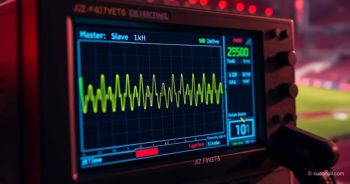
Diagnosing Phase with a Logic Analyzer
Verification of correct setup is done with an oscilloscope or logic analyzer. For testing:
- Set master timer (TIM8_CH1) to 1 kHz, 50% duty cycle
- Set slave timer (TIM4_CH2) with 90° phase shift
- Connect probes to the corresponding pins
Expected result:
- At zero shift, the master signal's rising edge aligns with the slave period start
- At 90° shift for a 1 ms period, the slave signal is offset by 250 µs

Key point: error is measured in bus clock cycles. For STM32F407 at 84 MHz bus, the minimum step is 11.9 ns. In practice at 1 kHz, this gives 0.012% accuracy.
Key Takeaways
- Method choice depends on accuracy requirements: for 0.01% error, use hardware synchronization; for 0.3%, software adjustment is acceptable
- Check timer compatibility: not all pairs support master-slave connection (see table in RM0090)
- Avoid stopping timers: hardware method doesn't interrupt signal generation during phase changes
- Account for slave device limits: one master can connect to no more than 4 slave timers
- Diagnose phase with an oscilloscope: visual verification is mandatory for critical systems
— Editorial Team










No comments yet.