The device and the operation of the input-output ports of the microcontrollers AVR. Part 1
- From the sandbox
- Tutorial
Operation of I / O ports
Having studied this material, in which everything is described in great detail and in detail with a large number of examples, you can easily master and program the input / output ports of the AVR microcontrollers.
We will consider an example on the ATMega8 microcontroller .
We will write the program in Atmel Studio 6.0 .
We will emulate the circuit in Proteus 7 Professional .
The microcontroller communicates with the outside world through input / output ports. The scheme of the input / output port is indicated in the datasheet:
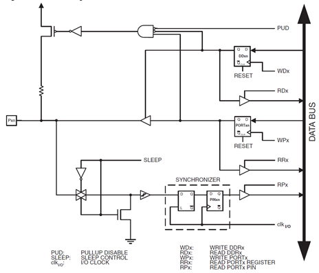
But for a novice, it’s quite difficult to figure out the scheme. Therefore, we simplify the scheme:
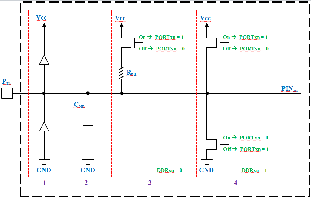
Pxn is the name of the microcontroller port leg, where x is the letter of the port (A, B, C or D), n is the number of the port category (7 ... 0).
Cpin is the parasitic capacitance of the port.
VCC - supply voltage.
Rpu - the disconnected load upper resistor (pull-up).
Portxn- bit n of the PORTx register.
PINxn - bit n of the PINx register.
DDRxn - bit n of the DDRx register.
Consider what the output of the microcontroller is. At the input of the microcontroller there is a small protection of two diodes (see 1)It is designed to protect the input of the microcontroller from short-term voltage pulses exceeding the supply voltage. If the voltage is higher than the power supply, then the upper diode will open and this voltage will be etched onto the power bus, where the power supply and its filters will already struggle with it. If a negative voltage (below the zero level) reaches the input, then it will be neutralized through the lower diode and will be extinguished to ground. However, the diodes there are frail and this protection only helps from microscopic impulses and interference. If a volt of 6-7 is supplied to the microcontroller leg at 5 volts of power, then the internal diodes will not save him.
A capacitor (see 2) is a stray output capacitance. Although tiny, it is present. Usually it is not taken into account, but it is. Do not bother, just know it.
Next are the control keys (see 3.4) . Each key is subject to a logical condition, which are drawn in the figure. When the condition is met, the key closes.
Each port of the AVR microcontroller (usually has the names A, B, and sometimes C or even D) has 8 bits, each of which is tied to a specific leg of the case. Each port has three special registers DDRx , PORTx and PINx (where x corresponds to the letter of the port A, B, C or D). The purpose of the registers:
DDRx - Configure the bits of port x for input or output.
Portx- Controlling the status of the outputs of port x (if the corresponding bit is configured as an output), or by connecting an internal pull-up resistor (if the corresponding bit is configured as an input).
PINx — Read the logical bit levels of port x.
PINхn is a read register. You can only read from it. The PINxn register contains information about the real current logic level on the port's pins. Regardless of the port settings. So if we want to find out what we have at the input, we read the corresponding bit of the PINxn register. Moreover, there are two boundaries: the border of the guaranteed zero and the border of the guaranteed unit - thresholds beyond which we can clearly determine the current logical level. For a five-volt power supply, this is 1.4 and 1.8 volts, respectively. That is, when the voltage decreases from maximum to minimum, the bits in the PINx register will switch from 1 to 0 only when the voltage drops below 1.4 volts, but when the voltage rises from minimum to maximum, the bit will switch from 0 to 1 only when the voltage reaches 1.8 volts. That is, there is a hysteresis of switching from 0 to 1, which eliminates chaotic switching under the influence of interference and interference, and also eliminates erroneous reading of the logic level between the switching thresholds.
With a decrease in the supply voltage, of course, these thresholds also decrease.
DDRxn is a port direction register. A port at a particular moment in time can be either an input or an output (but it does not matter for the status of the PINxn bits. You can always read the real value from PINxn ).
DDRxy = 0 - the output works as an INPUT.
DDRxy = 1 - the output works on EXIT.
PORTxn - output state control mode. When we adjust the output to the input, the type of input (Hi-Z or PullUp, more on that below) depends on PORTx .
When the pin is configured for output, the value of the corresponding bit in the PORTx register determines the status of the output. If PORTxn = 1 then the output is log.1, if PORTxn = 0 then the output is log.0.
When the foot is set to input, then if PORTxn = 0, then the output is in Hi-Z mode. If PORTxn = 1, then the output is in PullUp mode with a pull-up resistor of 100k before power supply.
Table. Port pin configuration.
DDRxn PORTxn I / O Comment
0 0 I (Input) Input High-impedance input. (I do not recommend using it, as interference from the power supply can be induced)
0 1 I (Input) Input Internal resistance is tightened.
1 0 O (Output) Output The output is low.
1 1 O (Output) Output The output is high.
The general picture of the port's operation is shown in the figures:
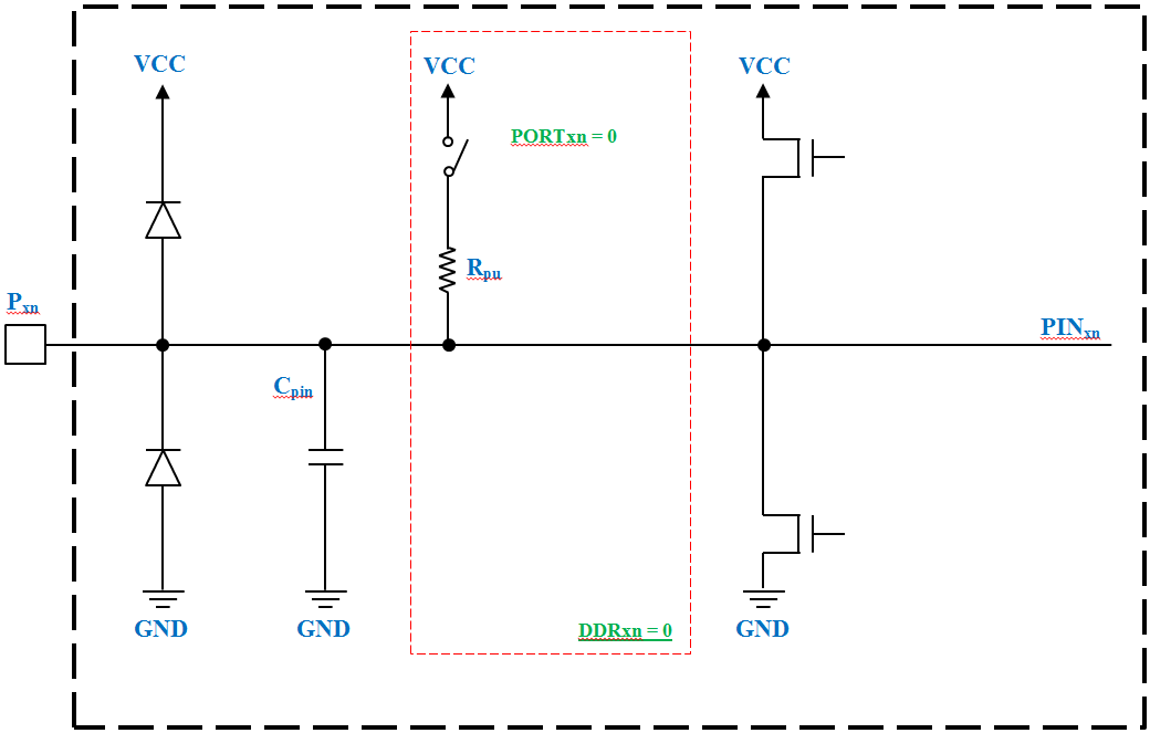
Fig. DDRxn = 0 PORTxn = 0 - Mode: HI-Z - high impedance input.
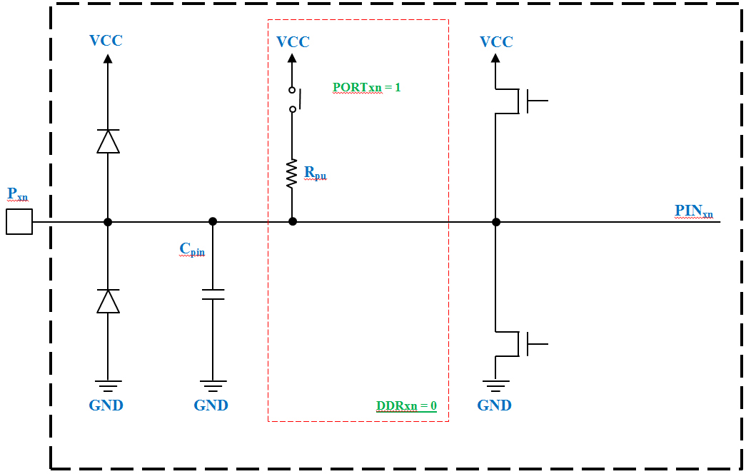
Fig. DDRxn = 0 PORTxn = 1 - Mode: PullUp - input with pull-up to log. 1.

Fig. DDRxn = 1 PORTxn = 0 - Mode: Output - output log 0. (almost GND)
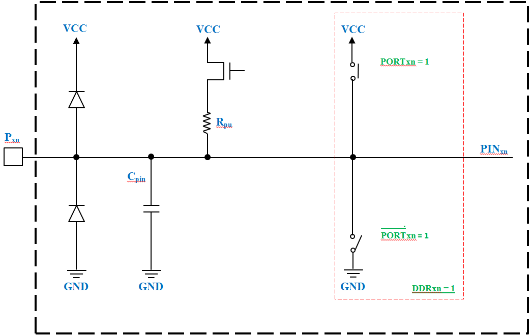
Fig. DDRxn = 1 PORTxn = 1 - Mode: Output - at the output of the log . 1 . (almost VCC)
Input Hi-the Z - vysokoimpendansnogo input mode.
This mode is enabled by default. All keys are open, and the port's resistance is very high. In principle, in comparison with other modes, it can be considered infinity. That is, electrically, the output, as it were, is not connected anywhere at all and does not affect anything. But! At the same time, he constantly reads his status into the PINn register and we can always find out what we have at the input is one or zero. This mode is good for listening to any data bus, because it has no effect on the tire. And what will happen if the entrance hangs in the air? And in this case, the voltage will jump on it depending on external interference, electromagnetic interference and generally on the phase of the moon and weather on Mars (an ideal way to chop random numbers!). Very often on the port in this case an unstable sine of 50 Hz - a tip from the 220V network, and in the registerPINn will change the 0 and 1 with a frequency of about 50Hz
Input pullup - input with pullup.
With DDRxn = 0 and PORTxn = 1, the tightening key closes and a 100kΩ resistor is connected to the line, which instantly brings the line not connected to anywhere to the log.1 state. The purpose of the pull-up is obvious - to prevent chaotic changes in the input state under the influence of pickups. But if a logical zero appears at the input (shorting the line to the ground with a button or another microcontroller / microcircuit), then a weak 100kOhm resistor will not be able to keep the voltage on the line at log.1 and there will be log.0 at the input.
Exit mode.
Here, I think, everything is clear - if we need to issue a log. 1 to the port, we enable the port to exit ( DDRxn= 1) and issue a log . 1 ( PORTxn = 1) - in this case, the upper key closes and a voltage close to the power appears on the output. And if you need log.0, then turn on the output port ( DDRxn = 1) and issue log.0 ( PORTxn = 1) - at the same time, the lower valve opens, which gives about zero volts on the output.
Having studied this material, in which everything is described in great detail and in detail with a large number of examples, you can easily master and program the input / output ports of the AVR microcontrollers.
- Part 1. I / O Port Operation
- Part 2. Connecting the LED to the I / O port line
- Part 3. Connecting a transistor to an I / O port line
- Part 4. Connecting the button to the I / O port line
We will consider an example on the ATMega8 microcontroller .
We will write the program in Atmel Studio 6.0 .
We will emulate the circuit in Proteus 7 Professional .
The microcontroller communicates with the outside world through input / output ports. The scheme of the input / output port is indicated in the datasheet:
But for a novice, it’s quite difficult to figure out the scheme. Therefore, we simplify the scheme:
Pxn is the name of the microcontroller port leg, where x is the letter of the port (A, B, C or D), n is the number of the port category (7 ... 0).
Cpin is the parasitic capacitance of the port.
VCC - supply voltage.
Rpu - the disconnected load upper resistor (pull-up).
Portxn- bit n of the PORTx register.
PINxn - bit n of the PINx register.
DDRxn - bit n of the DDRx register.
Consider what the output of the microcontroller is. At the input of the microcontroller there is a small protection of two diodes (see 1)It is designed to protect the input of the microcontroller from short-term voltage pulses exceeding the supply voltage. If the voltage is higher than the power supply, then the upper diode will open and this voltage will be etched onto the power bus, where the power supply and its filters will already struggle with it. If a negative voltage (below the zero level) reaches the input, then it will be neutralized through the lower diode and will be extinguished to ground. However, the diodes there are frail and this protection only helps from microscopic impulses and interference. If a volt of 6-7 is supplied to the microcontroller leg at 5 volts of power, then the internal diodes will not save him.
A capacitor (see 2) is a stray output capacitance. Although tiny, it is present. Usually it is not taken into account, but it is. Do not bother, just know it.
Next are the control keys (see 3.4) . Each key is subject to a logical condition, which are drawn in the figure. When the condition is met, the key closes.
Each port of the AVR microcontroller (usually has the names A, B, and sometimes C or even D) has 8 bits, each of which is tied to a specific leg of the case. Each port has three special registers DDRx , PORTx and PINx (where x corresponds to the letter of the port A, B, C or D). The purpose of the registers:
DDRx - Configure the bits of port x for input or output.
Portx- Controlling the status of the outputs of port x (if the corresponding bit is configured as an output), or by connecting an internal pull-up resistor (if the corresponding bit is configured as an input).
PINx — Read the logical bit levels of port x.
PINхn is a read register. You can only read from it. The PINxn register contains information about the real current logic level on the port's pins. Regardless of the port settings. So if we want to find out what we have at the input, we read the corresponding bit of the PINxn register. Moreover, there are two boundaries: the border of the guaranteed zero and the border of the guaranteed unit - thresholds beyond which we can clearly determine the current logical level. For a five-volt power supply, this is 1.4 and 1.8 volts, respectively. That is, when the voltage decreases from maximum to minimum, the bits in the PINx register will switch from 1 to 0 only when the voltage drops below 1.4 volts, but when the voltage rises from minimum to maximum, the bit will switch from 0 to 1 only when the voltage reaches 1.8 volts. That is, there is a hysteresis of switching from 0 to 1, which eliminates chaotic switching under the influence of interference and interference, and also eliminates erroneous reading of the logic level between the switching thresholds.
With a decrease in the supply voltage, of course, these thresholds also decrease.
DDRxn is a port direction register. A port at a particular moment in time can be either an input or an output (but it does not matter for the status of the PINxn bits. You can always read the real value from PINxn ).
DDRxy = 0 - the output works as an INPUT.
DDRxy = 1 - the output works on EXIT.
PORTxn - output state control mode. When we adjust the output to the input, the type of input (Hi-Z or PullUp, more on that below) depends on PORTx .
When the pin is configured for output, the value of the corresponding bit in the PORTx register determines the status of the output. If PORTxn = 1 then the output is log.1, if PORTxn = 0 then the output is log.0.
When the foot is set to input, then if PORTxn = 0, then the output is in Hi-Z mode. If PORTxn = 1, then the output is in PullUp mode with a pull-up resistor of 100k before power supply.
Table. Port pin configuration.
DDRxn PORTxn I / O Comment
0 0 I (Input) Input High-impedance input. (I do not recommend using it, as interference from the power supply can be induced)
0 1 I (Input) Input Internal resistance is tightened.
1 0 O (Output) Output The output is low.
1 1 O (Output) Output The output is high.
The general picture of the port's operation is shown in the figures:
Fig. DDRxn = 0 PORTxn = 0 - Mode: HI-Z - high impedance input.
Fig. DDRxn = 0 PORTxn = 1 - Mode: PullUp - input with pull-up to log. 1.
Fig. DDRxn = 1 PORTxn = 0 - Mode: Output - output log 0. (almost GND)
Fig. DDRxn = 1 PORTxn = 1 - Mode: Output - at the output of the log . 1 . (almost VCC)
Input Hi-the Z - vysokoimpendansnogo input mode.
This mode is enabled by default. All keys are open, and the port's resistance is very high. In principle, in comparison with other modes, it can be considered infinity. That is, electrically, the output, as it were, is not connected anywhere at all and does not affect anything. But! At the same time, he constantly reads his status into the PINn register and we can always find out what we have at the input is one or zero. This mode is good for listening to any data bus, because it has no effect on the tire. And what will happen if the entrance hangs in the air? And in this case, the voltage will jump on it depending on external interference, electromagnetic interference and generally on the phase of the moon and weather on Mars (an ideal way to chop random numbers!). Very often on the port in this case an unstable sine of 50 Hz - a tip from the 220V network, and in the registerPINn will change the 0 and 1 with a frequency of about 50Hz
Input pullup - input with pullup.
With DDRxn = 0 and PORTxn = 1, the tightening key closes and a 100kΩ resistor is connected to the line, which instantly brings the line not connected to anywhere to the log.1 state. The purpose of the pull-up is obvious - to prevent chaotic changes in the input state under the influence of pickups. But if a logical zero appears at the input (shorting the line to the ground with a button or another microcontroller / microcircuit), then a weak 100kOhm resistor will not be able to keep the voltage on the line at log.1 and there will be log.0 at the input.
Exit mode.
Here, I think, everything is clear - if we need to issue a log. 1 to the port, we enable the port to exit ( DDRxn= 1) and issue a log . 1 ( PORTxn = 1) - in this case, the upper key closes and a voltage close to the power appears on the output. And if you need log.0, then turn on the output port ( DDRxn = 1) and issue log.0 ( PORTxn = 1) - at the same time, the lower valve opens, which gives about zero volts on the output.