Weather Station on Arduino from A to Z. Part 3
Continued. The previous part .
Table of contents:
- Part 1. Requirements. The choice of iron. General scheme
- Part 2. Software. Central unit, iron
- Part 3. Central unit, software
- Part 4. Transom Sensor
- Part 5. MySQL, PHP, WWW, Android
Central unit. Software
Finally, we come to the most difficult part for any programmer - to describe in human terms what he has done there.
The source code for the server is about 1300 lines, including indents, but this should not scare you. The source text is provided with detailed comments, in this respect I will not be mistaken if I say that my source codes are described better than any others that you can find. In the comments directly in the source text you will find all the pinouts for connecting modules and all the necessary links to external documentation. The secret is simple - I wrote comments for myself all the time, “in the course of the play,” so I did not experience any difficulties with documentation.
As I already wrote, you can start without having all the modules at hand. For example, you can start without a radio module or ESP8266. The barometric pressure sensor BMP180 may also be missing. Add later. The truth is that in this case you (probably) will have to independently comment out in the sketch those parts of the code that are responsible for interacting with the missing blocks, but most likely this will not be necessary. The main thing is that at least something gathered and earned, then more fun to continue.
Specifically now, at this point in the story, we have not yet assembled the outside window (external) module and do not have our own web server with a database, then we don’t need it yet (but if you have it, connect right away so you don’t have to dig in):
- radio module nRF24L01 +
- WiFi module ESP8266.
And yet, I will begin, perhaps, with ESP8266, as the most problematic in programming and operating the module. The reason lies in the variety of execution of the modules themselves and their firmware.
As I wrote the standard AT-firmware for it have several disadvantages:
- they are still damp (as of 2016)
- I could not find a normal library for Arduino to control the ESP8266 module using AT commands, I had to “collective farm” myself.
I did not design the code for ESP8266 into a separate library, but simply wrote the necessary functions, so the sketch came out so long. And I implemented only the functionality I needed. All programming for ESP using AT commands is reduced as a result to parsing lines and setting delays between commands.
The source code for the server (central module) server.ino can be found and downloaded here .
Next I put the firmware for the ESP8266 in a file firmware/AT23-SDK101-nocloud.binand in the same directory there is documentation for the curious. After flashing the specified firmware, you can be sure that my sketch will work for you with WiFi as it was intended. I have not experimented with other AT firmware. The fact is that I managed to find the “advanced” non- AT firmware, and even participate in its creation, which is perfectly suited for our purposes ( here it is esp-link ). However, as often happens, everything happened after the completion of the current version of the weather station, so it was decided to leave everything as it is.
So, at the very beginning you will have to flash the specified AT firmware. There is nothing difficult here, but also simple. How to do this is described in many places on the network - ESP8266 - connecting and updating the firmware .
Since my USB-TTL converter did not have enough current power and the USB port was constantly falling off (this is a turn!), I electrically connected the module for its firmware using the “Arduino as a simple USB-to-Serial TTL converter” module.
Since I work in Linux, I was also using it with esptool.py. For the convenience of the firmware, I “nakolhozil” a small auxiliary board with switches (not described here).
After the firmware, you need to set the port speed of 57600 (as for SoftSerial, the port speed of 115200 is high and does not guarantee stable operation) with the command
AT+UART_DEF=57600,8,1,0,0Next, you need to slightly change the standard Arduino IDE libraries, namely, in the file, arduino/hardware/arduino/avr/libraries/SoftwareSerial/SoftwareSerial.hchange the corresponding line to
#define _SS_MAX_RX_BUFF 128 // RX buffer sizein the file, arduino/hardware/arduino/avr/cores/arduino/HardwareSerial.hchange the corresponding lines to
#define SERIAL_TX_BUFFER_SIZE 128#define SERIAL_RX_BUFFER_SIZE 128and in the file arduino/hardware/arduino/avr/cores/arduino/USBAPI.hchange the corresponding line to
#define SERIAL_BUFFER_SIZE 128Strictly speaking this is wrong, because when updating the Arduino SDK, these files will most likely be overwritten and you will have to repeat all the fixes again. According to science, we have to invent our library, which manipulates the specified values (if it works), but this is an amateur.
One way or another, the preliminary manipulations are over.
Now go directly to the code of the central unit (server) server.ino
In the very first lines you should change the access settings for your WiFi point.
constString SSID = "...";
constString PASSWORD = "...";
work with the web server will be discussed in detail later.
Next come the (commented out) debug definitions:
//#define DEBUG//#define DEBUG_RF//#define DEBUG_ESP//#define DEBUG_LOG_SDIf something goes wrong, you can always uncomment them, recompile and reload the sketch and get more debugging information in the console or write it to a file on the SD card. And you can uncomment only what you need. For example, is the nRF24L01 + module swindling? Then uncomment only DEBUG_RF, etc.
Next come extensive comments with pinout, initialization and a detailed description of the entire periphery.
Here you can change the number of the radio channel for nRF24L01 +
#define RF_CHANNEL 73Next comes void setup()that it is made clear from detailed comments. Well, then void loop(), the code to work with the web server is not yet considered.
After casting the sketch, your central unit will revive and something will show you, but not immediately, but after 10 minutes - the value DELAY_LOCAL_SENSOR. You can change it of course.
The display should show: room temperature and humidity (data coming from the DHT11 sensor) and barometric pressure (from BMP180).
For the display on the LCD 16 × 4 answer functions:
void lcdClearRow(int row)
// Печатает на экране показания удалённых, уличных датчиковvoid lcdPrintOutdoor(int temperature, int humidity, float voltage)
// Печатает на экране показания внутренних, домашних датчиковvoid lcdPrintHome(int temperature, int humidity, int pressure)
void lcdPrintInfo(char info[LCD_MAX_COLS])
void lcdPrintStatus()
void lcdPrintLastSensorTime()
LCD1604 display design is as follows.
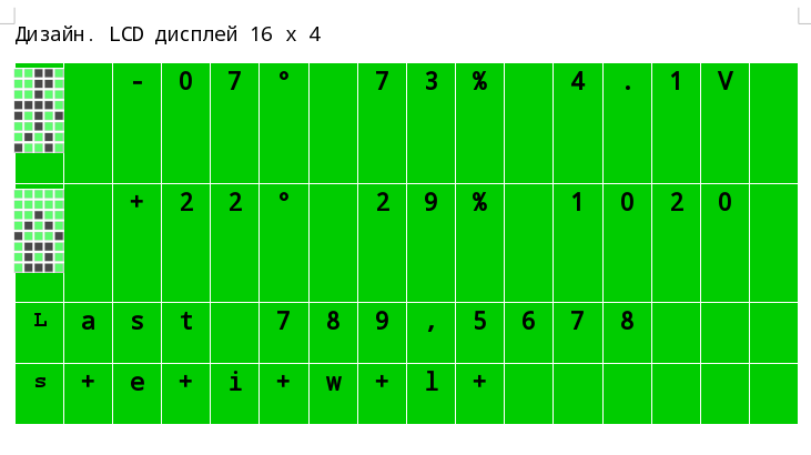
The first (top) line prints a stylized icon (walking man) designed to indicate the weather on the street (went outside, walking down the street). Invented the icon himself, so if you have a better idea (which fits 5x8 pixels), you can indicate in the comments (in the form of a byte-array). You can practice in pixel art here the Custom Character Generator for HD44780 LCD Modules . The same line prints the power supply voltage of the windowed module.
The second line contains “weather in the house” and atmospheric pressure. The house icon is standard, understandable to everyone.
The third line lcdPrintLastSensorTime()prints how much time has passed (in seconds) since the last sensor readings, respectively, of the street and, comma-separated, home time reading. It is useful to know for sure that the weather station does not show the weather yesterday. In fact, this is debug information and can be removed in the final version.
And in the last fourth line of the screen, using the function, the lcdPrintStatus()status information is printed, where
- s is a local pressure sensor
- e is the ESP8266 module
- i is a wifi connection
- w is the availability of the web server
- l - log file on SD card
After each of these symbols, there will be a “plus” or “minus” sign, which means no or there are errors, problems in the work of the respective modules.
Returning to the question of the choice of iron, I will explain the advantages of choosing a text LCD1604 display over a graphic one. The fact is that the LCD1604 modules purchased from different vendors will in most cases be the same and predictable in connection and easy to program. What can not be said about graphic displays, although you can draw and show on them much more. The intelligibility of the image from a distance of several meters is again better for a text display, yes, you can make a bigger font on a graphic display, but can you fit a lot on it?
Further. As soon as you fill in the sketch and make sure that everything works as it should, you can reconnect the “motherboard” of the Arduino Mega to an external power source. Or leave it as it is, connected to the USB of the computer to look at all this beauty in the debug console.
If you do not have all the blocks in the collection, then you can comment out unnecessary code. Although, I repeat, it should work this way, you will simply receive error messages in the console. How to get around this?
For example, you have not yet purchased the BMP180 atmospheric pressure sensor. In the sketch server.ino we look for the lines responsible for connecting the corresponding libraries, in our case this
#include<Wire.h>#include<Adafruit_Sensor.h>#include<Adafruit_BMP085_U.h>Commenting this block.
Next, in the Arduino IDE, we start compiling the code (not the firmware) and look at which lines the compiler curses. Commenting on these lines. The operation is repeated until the code is assembled normally, without errors. Before editing, it will be a good practice to create a copy of the sketch, so that when the correct sensor comes from sunny China, do not repeat all the operations back.
References to used libraries are given in the source code. If there is no such link, then the standard Arduino IDE library was used.
Just in case, all the libraries (except the standard ones) that I used are stored in the libraries directory . Strictly speaking, this is wrong. You should download the latest versions of the libraries from their official repositories (with bug fixes, new features), but in case they are difficult to find, either they have already been deleted, or the old versions are not supported, only for this case I saved all the libraries used.
Next comes the assembly of the behind-the-window sensor, so this part came out short so as not to mix.