Weather Station on Arduino from A to Z. Part 2
Continued. The previous part .
Table of contents:
- Part 1. Requirements. The choice of iron. General scheme
- Part 2. Software. Central unit, iron
- Part 3. Central unit, software
- Part 4. Transom Sensor
- Part 5. MySQL, PHP, WWW, Android
Soft Component selection
The choice of hardware and software is closely interrelated as "chicken and egg". Where to start, with iron, with software? If you have good hardware, but there are no drivers, libraries and software for it (IDE, firmware utilities, etc.), then it is useless, and vice versa.
Therefore, I am telling once again about the choice between the nRF24L01 + and ESP8266 for the connection of remote sensors with the central unit.
The fact is that the ESP8266 is not just a stupid WiFi adapter, it has an onboard microcontroller that is superior to Arduino in terms of power and memory . By default, the ESP8266 has a firmware in the form of a set of AT commands; in this case, ESP is used as a simple modem. But there are more advanced firmware, here ESP8266 can even act as a web server, and, of course, control sensors like Arduino.
However, all these advanced firmware have flaws that did not allow (in total with the hardware questions about which I already wrote) to apply ESP8266 in this project:
- all firmware is still very raw (as of 2016)
- some ready are not free
- The entry threshold for debugging and making changes is much higher than that of the Arduino.
As a result, I did not find a ready-made suitable firmware, and I am not ready to create my own yet. The ESP8266 chip is an extensive and interesting topic.
In turn, standard AT-firmware also have disadvantages:
- they are still damp (as of 2016)
- I could not find a normal library for Arduino to control the ESP8266 module using AT commands, I had to "collective farm" myself.
On the other hand nRF24L01 + radio is simple and straightforward to work with him have a super Lieb RadioHead and no problems with programming. The library is well documented, which is important.
RadioHead allows you to transfer data structures (and not just individual numbers), which is implemented in this project. Looking ahead I will say, RadioHead can reliably transmit data, with repetitions if it did not reach the first time. All these things the library takes over.
For energy saving I use the Low Power Library library , it is simple and contains only what you need.
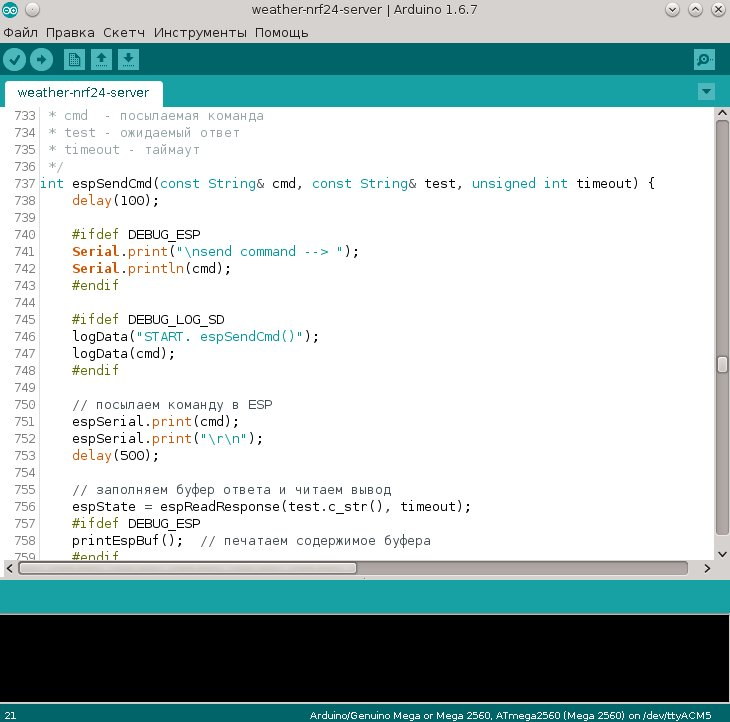
Here is a piece of code:
// по умолчанию устанавливается 2.402 GHz (канал 2), 2Mbps, 0dBm
rfdata.init();
// передача данных на сервер (с повторами, если потребуется)
rfdata.sendtoWait((uint8_t*)&dhtData, sizeof(dhtData), SERVER_ADDRESS);
// засыпаемLowPower.powerDown(SLEEP_8S, ADC_OFF, BOD_OFF);`
Everything!
In the case of the use of ESP8266 in a remote sensor, I would be forced to create a WiFi access point and somehow transfer data (where is the firmware, where is the software?). Or allow the sensor to directly send data to the web server, and the central unit (which in this case stops playing the role of “central”) learn to read the data from there to display it on the board.
In other words, I went through more autonomy from the WiFi Internet and PHP + MySQL server. You can start “riveting” the weather station already without access to the Internet and / or hosting for the server, in this case you don’t need ESP8266, just add it later.
The Adafruit DHT Sensor Library is available for reading data from DHT sensors . Working with it is simple and straightforward.
The Adafruit BMP085 Unified library is suitable for the pressure sensor , which requires an abstract level library Adafruit Sensor .
All libraries have examples of sketches.
That's all perhaps with the theoretical part. “Our goals are clear, the objectives are defined. For the work, comrades! ”
Central unit. Iron
Well, finally, after all the misrepresentations, we proceed to the assembly!
Note . If you have never collected a weather station (oh well!), Then you can start without all the details at hand. For example, you can start without a radio module and / or ESP8266. The barometric pressure sensor BMP180 may also be missing. Add later. True, in this case you will have to independently comment out in the sketch those parts of the code that are responsible for interacting with the missing blocks, but this is not so difficult. I'll show you how.
The main thing is that at least something has gathered and earned, then more fun to continue.
As already mentioned, the central unit is based on the Arduino MEGA. We will also need:
- temperature and humidity sensor DHT11
- barometric pressure sensor type BMP180
- WiFi module ESP8266
- radio module type nRF24 2.4 GHz
- LCD1604 type display (4 lines of 16 characters each), you can buy for $ 5
- power supply with output of 5-12 V DC (I used charging from a mobile with a USB output which is convenient)
- breadboard for soldering, soldering iron, rosin, solder or ordinary solderless arduino breadboard. Personally, I soldered for reliability, because the project was clearly long-playing and did not want to suffer because of the wiring that was accidentally pulled out of the model.
You can buy a prototype card for desoldering from $ 1. Take a larger size to be enough for all connections. And once again: read the description before buying, not the picture.
A bounce-free board can be bought from $ 2. Take a larger size to be enough for all connections.
The connecting wires are of the types we need:
- Dupont cable "father-mother" (there is a "father-father", "mother-mother"). This is a train of several wires with different colors of insulation and connectors for the pin contacts for Arduino. With such wires it is convenient to connect boards and sensors directly to Arduino without using a breadboard.
- Conventional connecting wires for solderless prototyping board for Arduino.
- Wire bundle for soldering.
First of all I disassembled the LCD-1604 scoreboard. First I soldered the pins to the board, then the connectors to the breadboard.
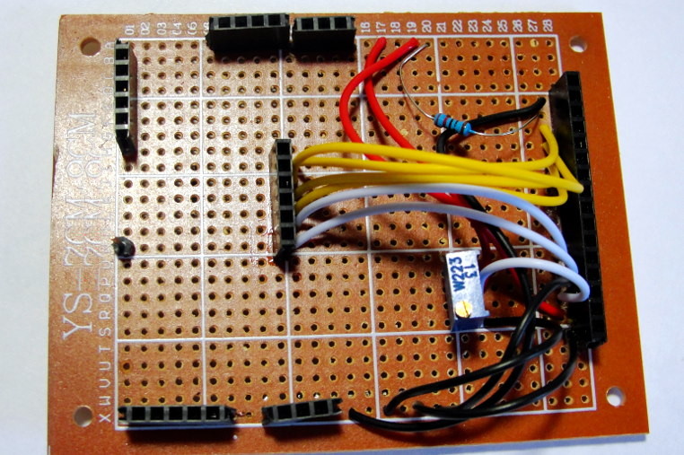
Bottom view.
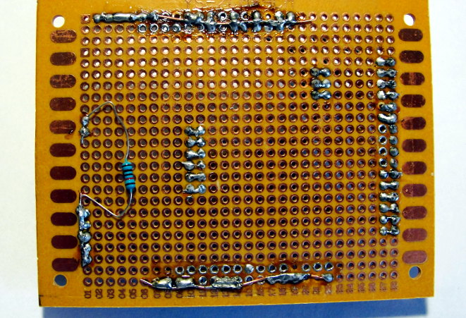
Payal on influx without prior layout, so here no scheme will not be given. Do as it is more convenient, it will not be worse. Adhere only to the principle that the black wire is always the earth, the red is the “plus” of the power supply, the other colors as it is. It turned out so.
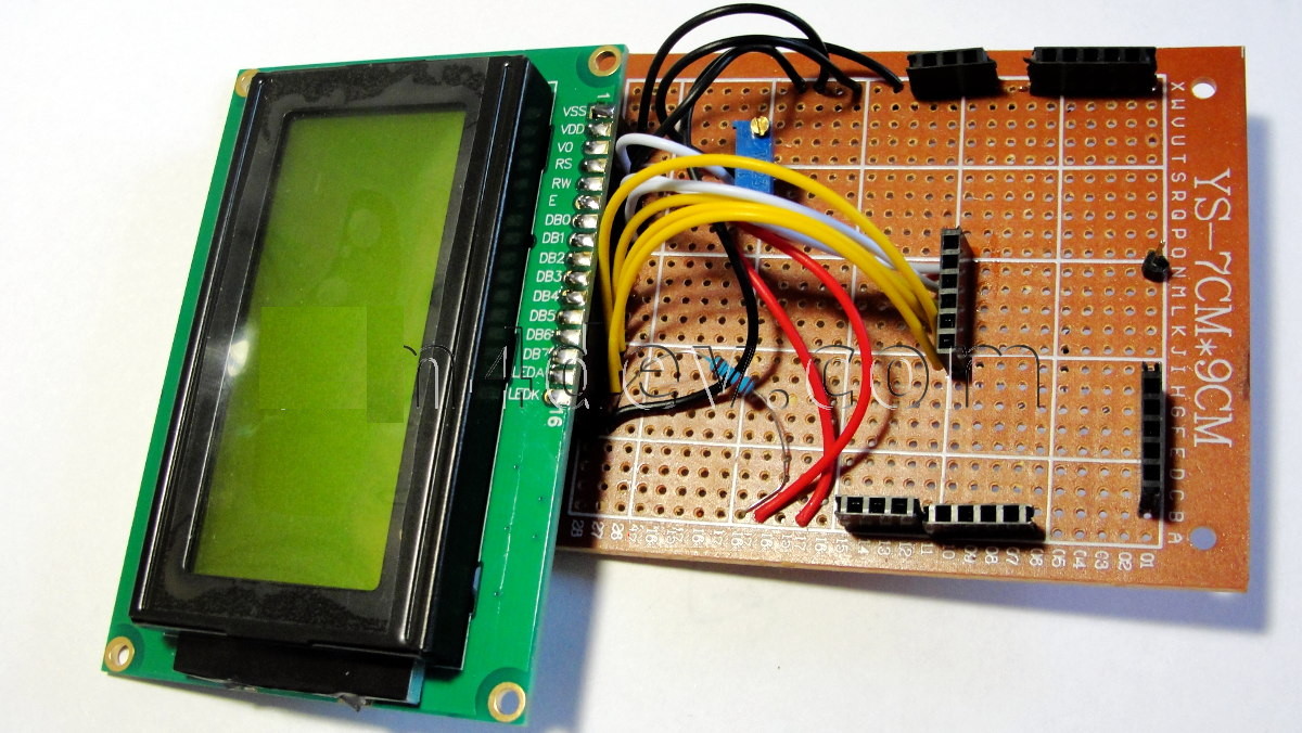

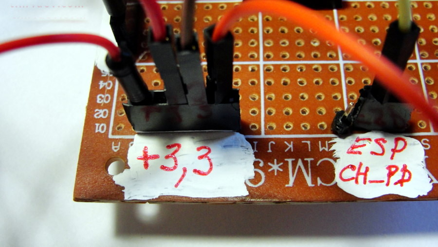
In order not to forget where there are any connectors, I “painted” with the white corrector sections of the board in the neighborhood and made the appropriate inscriptions. Ugly? But practical and fast, it's a prototype!
Pinout and connection
16 × 4 LCD1604 display
For more information about the display and how to work with it, google “Working with symbolic LCDs based on HD44780”. Note that you need to carefully consider the polarity of the power supply to the LCD indicator and that the supply voltage is in the range of + 4.5 ... 5.5 V. Inattentive attitude to this can lead to the indicator failure!
| Pin LCD 1604 | Arduino MEGA | Arduino uno | Description |
|---|---|---|---|
| VSS | GND | GND | GND |
| Vdd | 5 V | 5 V | 4.7 - 5.3V |
| RS | 22 | four | A high level means that the signal at the outputs DB0 — DB7 is data, a low one — the command |
| Rw | GND | GND | Defines the direction of the data (read / write). Since the operation of reading data from the indicator is usually unclaimed, it is possible to set a low level permanently at this input. |
| E | 23 | five | A pulse with a duration of at least 500 ms on this pin determines the signal for reading / writing data from the pins DB0-DB7, RS and WR |
| DB4 | 24 | eight | Incoming / outgoing data |
| DB5 | 25 | 9 | |
| DB6 | 26 | ten | |
| DB7 | 27 | eleven | |
| LED A + | + 5V or 220 ohm resistor → + 5VLED-A 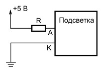 | ||
| LED B- | GND | ||
| V0 | GND or trimmer on 10kohm 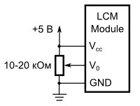 |
Software initialization will look like this:
// Arduino MEGALiquidCrystal lcd(22, 23, 24, 25, 26, 27);
// Arduino UNOLiquidCrystal lcd(4, 5, 8, 9, 10, 11);
Temperature, humidity DHT11
Connecting temperature and humidity sensor DHT11 (SainSmart). Position the sensor face up, the findings will be described from left to right.
| DHT11 | Arduino mega |
|---|---|
| DATA | Digital pin 2 (PWM) (see below DHTPIN) |
| VCC | 3.3—5 V (5 V recommended, better external power) |
| GND | GND |
Software initialization
#define DHTPIN 2 // цифровой пин Digital pin 2 (PWM)#define DHTTYPE DHT11 // см. DHT.h// инициализацияDHT dht(DHTPIN, DHTTYPE);Barometer BMP180
Connection of the atmospheric pressure sensor BMP180 (barometer) + temperature via I2C / TWI interface.
| BMP180 | Arduino mega |
|---|---|
| VCC | not connected |
| GND | GND |
| SCL | 21 (SCL) |
| SDA | 20 (SDA) |
| 3.3 | 3.3 V |
For UNO: A4 (SDA), A5 (SCL).
// инициализация
Adafruit_BMP085_Unified bmp = Adafruit_BMP085_Unified(10085); // sensorID
nRF24L01 +
Brief characteristics:
- The frequency range of 2.401 - 2.4835 GHz
- 126 channels. The zero channel starts at 2400 MHz and further in 1 MHz steps, for example, channel 70 is located at 2470 MHz, respectively. When setting the transmission speed of 2Mbps, the channel width is 2 MHz.
- Power 1.9 - 3.6 V (3.3 V recommended)
Here is the pinout of the module.
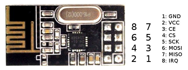
Some advise you to immediately solder a 100nF ceramic capacitor (possible 1µF, 10µF) to the RF power pins to avoid electrical interference.
Pinout nRF24L01 + (look at the top of the board where the chip, pins should be below):
| pin 2 3.3V | pin 4 CSN | pin 6 MOSI | pin 8 IRQ |
| pin 1 GND | pin 3 CE | pin 5 sck | pin 7 MISO |
Connection for meteorological station:
| Arduino mega | nRF24L01 + |
|---|---|
| 3.3 V | VCC pin 2 (better external power) |
| pin D8 | CE pin 3 (chip enable in) |
| SS pin D53 | CSN pin 4 (chip select in) |
| SCK pin D52 | SCK pin 5 (SPI clock in) |
| MOSI pin D51 | SDI pin 6 (SPI Data in) |
| MISO pin D50 | SDO pin 7 (SPI data out) |
| IRQ pin 8 (Interrupt output) is not connected | |
| GND | GND pin 1 (ground in) |
Programming of the radio module will be described in detail in the program part.
ESP8266
Pinout ESP8266 (look at the top of the board where the chips, pins should be below):
| GND | GPIO2 | GPIO0 | Rx |
| Tx | CH_PD | RESET | VCC |
ESP8266 Connection for Weather Station:
| ESP8266 | Arduino mega |
|---|---|
| Tx | 10 pin (SoftwareSerial RX) |
| Rx | 11 pin (SoftwareSerial TX) |
| VCC | 3.3 V |
| GND | GND |
| CH_PD | Through 10K to 3.3V Arduino Resistor |
| GPI0 | Not necessary. Through 10K to 3.3V Arduino Resistor |
| GPI2 | Not necessary. Through 10K to 3.3V Arduino Resistor |
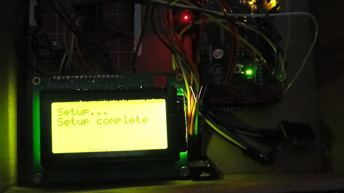
KDPV
Central unit assembly. "Motherboard" cut out of a cardboard box from under the shoes and cogs for 3 screwed everything else to it.
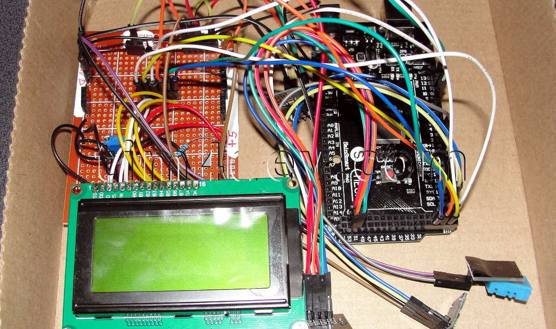
As we see in this place, all the power is supplied from the Arduino pins, i.e. Nothing goes directly to the power supply, and so far there is enough power.
Look like that's it. Forgot nothing.
Solder, connect. In the next part a working sketch for the central unit will be shown and our weather station will show something already.