Raspberry pi thermometer with wireless sensor on rf 433 and attiny85 MK
This article describes my experience in creating a wireless temperature sensor based on the Attiny85 + ds18b20 + rf 433 TX MK battery. Attiny85 data reception and programming is based on the Raspberry pi B +.
On Habré and not only there is much interesting about the Raspberry Pi mini-computer. I decided to get such a toy in my house. Please do not criticize the choice of this particular platform. The choice fell only due to the rather extensive documentation and many different examples of the use of this mini-computer.
It was decided to start with temperature sensors. At hand was a pair of sensors (ds18b20, ds1822). The abundance of articles on connecting these sensors did not require much time in order to attach them and get temperature values. I had to purchase a DHT22 sensor, which allowed me to record not only temperature, but also humidity. Lighttpd + php + mysql was raised on raspberries. Data from sensors is now recorded with a certain frequency in the database. From the article “Internet thermometer or telemetry of a country house”The idea of plotting in Highcharts was taken . Not having the special skills of a programmer, I had to spend a couple of free evenings. As a result, you could go to the local page and look at the current temperature in the street, in the apartment, as well as the dynamics of temperature changes over the past n days.
For some time, two DHT22 and ds18b20 sensors hung outside the window. The temperature readings of these sensors usually differed by a few tenths. The goal was not to take measurements with very high accuracy and such differences in the readings were quite fine with me.
All in the same article links to the openweathermap.com and narodmon.ru projects were spied. Thus, the data from the temperature and pressure sensor (DHT22) began to be sent to these two services.
I did not understand the Openweathermap service very well. I liked the people's monitoring more. On the map you can visually compare your readings with the data of other sensors in your own city. There are applications for phones on Android and iOS.
Everything, of course, is wonderful, but the problems, as always, are in the details. The windows of my apartment face south. And sensors often find themselves in the sun. When the temperature is below freezing, the sensors on the sunny side could show up to +10. At the same time, the sensors are not in direct sunlight (hidden behind the air conditioning unit). I did not really want to pull the wires through the corridor to the north side. Therefore, it was decided to master wireless technology.
RF 433 was chosen for reception and transmission. Again, since I am a beginner in the world of electronics and programming, I decided not to spend a lot of money and leave my choice to the most budget option. The cost of the receiver + transmitter is about $ 3.
Work scheme: MK - rf 433 (transmitter) -> rf 433 (receiver) - Raspberry pi.
It was necessary to choose a microcontroller. There is an excellent article on Instructables on how to program the Attiny85 microcontroller with raspberry pi. I did not meet the translation of this article or something similar to Habré. So if interest is shown, a translation can be made.
The choice of a microcontroller has been made. An experienced couple was purchased in the market at a price of $ 2-3 per piece. For simplicity, I decided to start with ds18b20.
The operation algorithm is as follows: the MK reads the temperature value from the sensor, the voltage is read (we will be supplied by batteries), the checksum is calculated, this data is sent several times, and then we send this entire system to sleep for several minutes to save power.
rf 433 (receiver) + Raspberry pi listens on the air while waiting for data.
On the breadboard we assemble a circuit for MK programming:

The connection diagram is taken from the Instructables website. Resistors can be taken a little different 1-5K, which is at hand. I personally have not tried more than 4.7 KOhm. There, on the breadboard, we connect the sensor and the transmitter to the attini as shown in the diagram:
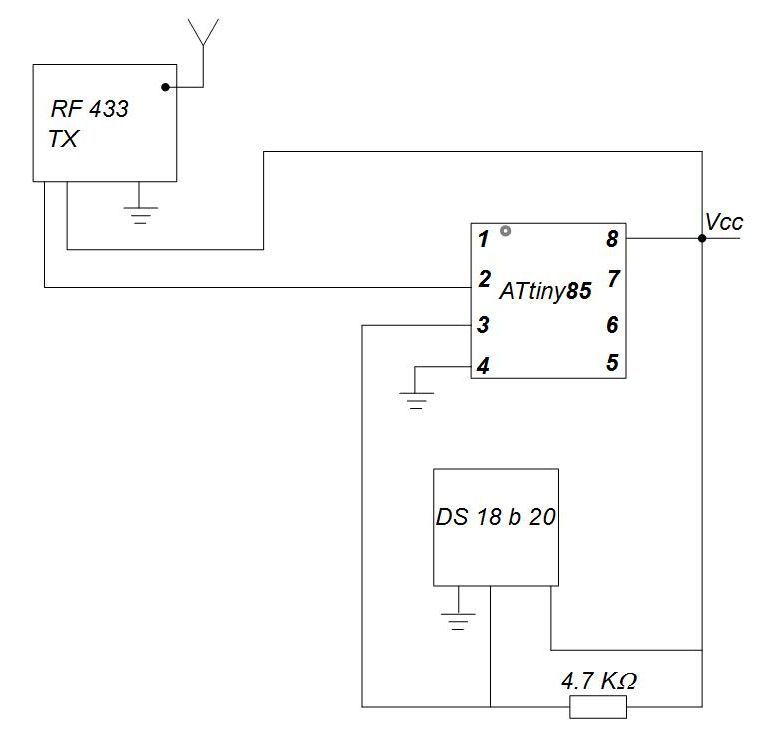
Thus, we got a connected MK for programming using the Raspberry Pi and connected sensor and RF433 transmitter. It remains to connect the receiver to rasspbery pi. My wiring diagram:
Raspi RF433 RX
GPIO 27 (13) -> DATA
GND (14) -> GND
5V, Vcc (4) -> Vcc
Pins on raspberry pi wiring diagrams according to their numbering in the WiringPI library for working with GPIO, their physical location on the board in brackets.
And so it all looks on the breadboard: We

figured out the hardware, let's move on to the software part.
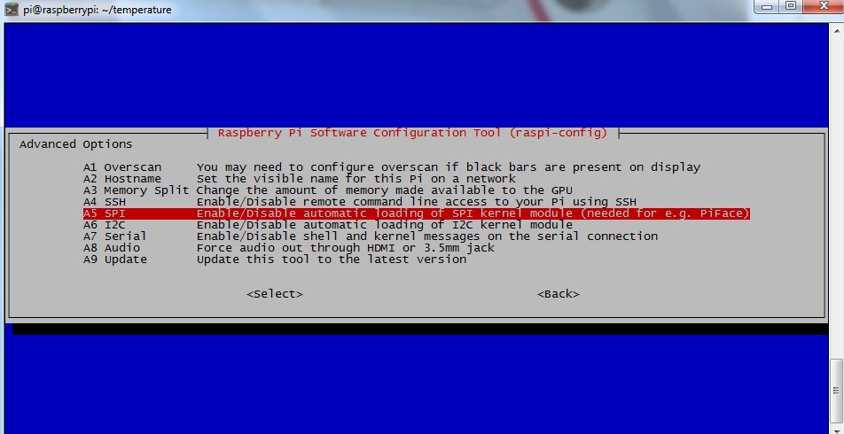
How to install Raspbian will not be considered. In raspi-config, enable SPI.
Now we need to download and install AVRDude (AVR Downloader-Uploader) - a cross-platform free console program designed for flashing Atmel microcontrollers from the AVR series.
To work with GPIO, you need to download and install WiringPi:
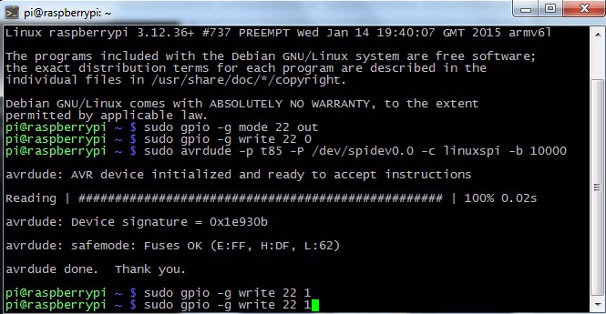
Check if we did everything right:
If we did everything right, we should get this result:
At this stage, the preparatory work is over.
I was not able to find working C code that would fulfill all the tasks assigned. I had to collect in pieces from various repositories (and not only).
I used this repository to read the temperature . To determine the voltage used this repository .
I used the repository to send the signal .
What I got laid out on github. The code we need is located blinky.c , 1wire.c , 1wire.h , manchester.c , manchester.h .
It remains to collect everything and program our Attink 85.
We create or copy the Makefile in the same place where the files of our project are located.
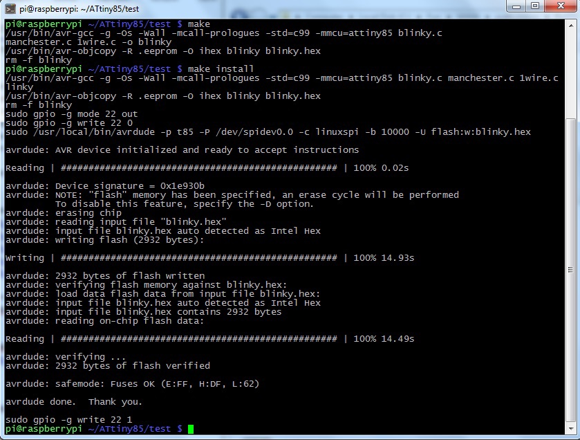
We carry out:
And if all is well and there will be no errors in the program code, we execute:
We relaxed and watched the recording of our program on the microcontroller:
If everything is fine and nothing hurt us, this is the stage of programming our MK.
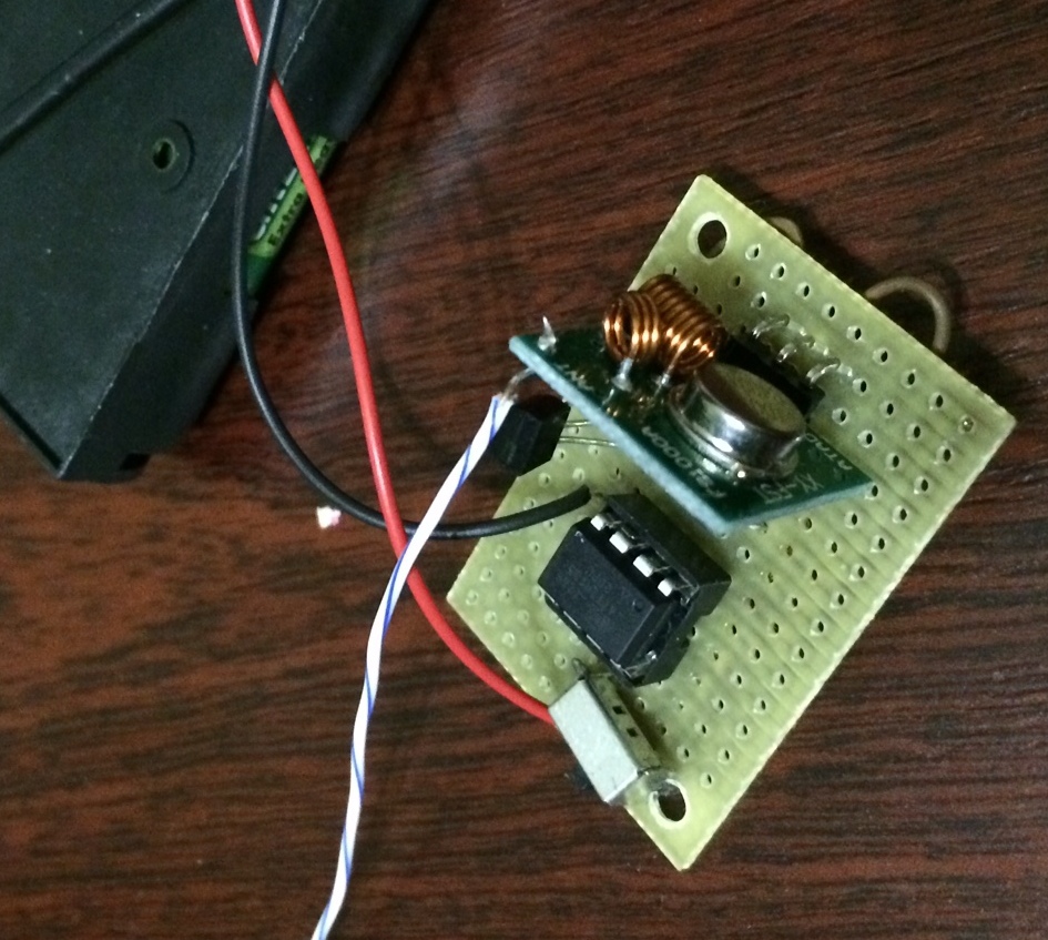
According to the scheme above, we collect everything on a separate breadboard without Rasspberry Pi and battery power. I had a case for three AA batteries. This is my first project and I did not bother much with the wiring on the board. Here's what I ended up with:
Now it's time to receive the temperature data from the transmitter.
There is a good article on decoding the X10 RF protocol. There are examples of programs for receiving a signal over RF433. For the receiver, the code from this article was taken as the basis, namely X10RFSnifferBit.cpp. The program sits and waits for a signal of a certain duration, or rather, several consecutive signals, the so-called lock. After that, the reception of the required number of bits begins.
We change the lock to our values, add a checksum check and write the received values to a file. The received information is written to a file in the form of an id sensor, battery charge, temperature and checksum.
It looks like my rf433recieve.cpp , and it looks like an example of a file in which we write the received data.
In my case, RF 433 RX connected to GPIO 2 (13). When connecting to another pin, you must change the GPIO number in the line:
We collect and run our program ( Makefile ). You need to run as root:
Now on raspberry pi we take our temperature and write to the received data in a file.
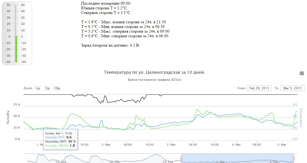
While all this was being assembled and programmed, the data from the local database was transferred to the hosting. I pull the file on the crown where we write our temperature, battery charge data and send the data to the hosting in the database. Then the schedule for the last few days is built. This is how the result looks:
When everything was assembled, it was necessary to check the range of data transmission at home with various antennas.
On the receiver, the antenna is a piece from a twisted pair cable with a length of about 17 cm. For the transmitter, I tried several variations: a twisted pair cable of 17 and 34 cm; a copper core of about 1 mm in diameter and 34 cm long in the form of a straight line and in the form of a spiral. The worst thing in my experiments was a copper core in the form of a spiral, the remaining antennas gave approximately the same option, so I decided to leave a piece of twisted pair 17 cm. In terms of range, I managed to break through three brick walls and a distance of about 10 m. An increase in partitions and distance led to that the receiver did not receive a signal at all or tried to catch one two signals from lock-a.
Now there is a test period and the sensor is laid on the balcony (also on the sunny side). On the open balcony, the sensor was not hidden from the sun and obviously the balcony is ventilated worse than the sensor hidden behind the air conditioner in the shade. Therefore, on sunny days, the wireless sensor gives peaks and you can track solar activity from these peaks.
What's next? Then I wanted to try a bunch of MK Attiny85 + RF 433 TX + DHT22, but that's another story ...
Foreword
On Habré and not only there is much interesting about the Raspberry Pi mini-computer. I decided to get such a toy in my house. Please do not criticize the choice of this particular platform. The choice fell only due to the rather extensive documentation and many different examples of the use of this mini-computer.
It was decided to start with temperature sensors. At hand was a pair of sensors (ds18b20, ds1822). The abundance of articles on connecting these sensors did not require much time in order to attach them and get temperature values. I had to purchase a DHT22 sensor, which allowed me to record not only temperature, but also humidity. Lighttpd + php + mysql was raised on raspberries. Data from sensors is now recorded with a certain frequency in the database. From the article “Internet thermometer or telemetry of a country house”The idea of plotting in Highcharts was taken . Not having the special skills of a programmer, I had to spend a couple of free evenings. As a result, you could go to the local page and look at the current temperature in the street, in the apartment, as well as the dynamics of temperature changes over the past n days.
For some time, two DHT22 and ds18b20 sensors hung outside the window. The temperature readings of these sensors usually differed by a few tenths. The goal was not to take measurements with very high accuracy and such differences in the readings were quite fine with me.
All in the same article links to the openweathermap.com and narodmon.ru projects were spied. Thus, the data from the temperature and pressure sensor (DHT22) began to be sent to these two services.
I did not understand the Openweathermap service very well. I liked the people's monitoring more. On the map you can visually compare your readings with the data of other sensors in your own city. There are applications for phones on Android and iOS.
Everything, of course, is wonderful, but the problems, as always, are in the details. The windows of my apartment face south. And sensors often find themselves in the sun. When the temperature is below freezing, the sensors on the sunny side could show up to +10. At the same time, the sensors are not in direct sunlight (hidden behind the air conditioning unit). I did not really want to pull the wires through the corridor to the north side. Therefore, it was decided to master wireless technology.
Formulation of the problem
RF 433 was chosen for reception and transmission. Again, since I am a beginner in the world of electronics and programming, I decided not to spend a lot of money and leave my choice to the most budget option. The cost of the receiver + transmitter is about $ 3.
Work scheme: MK - rf 433 (transmitter) -> rf 433 (receiver) - Raspberry pi.
It was necessary to choose a microcontroller. There is an excellent article on Instructables on how to program the Attiny85 microcontroller with raspberry pi. I did not meet the translation of this article or something similar to Habré. So if interest is shown, a translation can be made.
The choice of a microcontroller has been made. An experienced couple was purchased in the market at a price of $ 2-3 per piece. For simplicity, I decided to start with ds18b20.
The operation algorithm is as follows: the MK reads the temperature value from the sensor, the voltage is read (we will be supplied by batteries), the checksum is calculated, this data is sent several times, and then we send this entire system to sleep for several minutes to save power.
rf 433 (receiver) + Raspberry pi listens on the air while waiting for data.
Task completion
Assembly and connection
On the breadboard we assemble a circuit for MK programming:
The connection diagram is taken from the Instructables website. Resistors can be taken a little different 1-5K, which is at hand. I personally have not tried more than 4.7 KOhm. There, on the breadboard, we connect the sensor and the transmitter to the attini as shown in the diagram:
Thus, we got a connected MK for programming using the Raspberry Pi and connected sensor and RF433 transmitter. It remains to connect the receiver to rasspbery pi. My wiring diagram:
Raspi RF433 RX
GPIO 27 (13) -> DATA
GND (14) -> GND
5V, Vcc (4) -> Vcc
Pins on raspberry pi wiring diagrams according to their numbering in the WiringPI library for working with GPIO, their physical location on the board in brackets.
And so it all looks on the breadboard: We
figured out the hardware, let's move on to the software part.
Install the necessary software and program Attiny85
How to install Raspbian will not be considered. In raspi-config, enable SPI.
Now we need to download and install AVRDude (AVR Downloader-Uploader) - a cross-platform free console program designed for flashing Atmel microcontrollers from the AVR series.
sudo apt-get install bison automake autoconf flex git gcc
sudo apt-get install gcc-avr binutils-avr avr-libc
git clone https://github.com/kcuzner/avrdude
cd avrdude/avrdude
./bootstrap && ./configure && sudo make install
To work with GPIO, you need to download and install WiringPi:
cd ~
git clone git://git.drogon.net/wiringPi
cd wiringPi
./build
Check if we did everything right:
sudo gpio -g mode 22 out
sudo gpio -g write 22 0
sudo avrdude -p t85 -P /dev/spidev0.0 -c linuxspi -b 10000
sudo gpio -g write 22 1
If we did everything right, we should get this result:
At this stage, the preparatory work is over.
I was not able to find working C code that would fulfill all the tasks assigned. I had to collect in pieces from various repositories (and not only).
I used this repository to read the temperature . To determine the voltage used this repository .
I used the repository to send the signal .
What I got laid out on github. The code we need is located blinky.c , 1wire.c , 1wire.h , manchester.c , manchester.h .
It remains to collect everything and program our Attink 85.
We create or copy the Makefile in the same place where the files of our project are located.
We carry out:
makeAnd if all is well and there will be no errors in the program code, we execute:
make installWe relaxed and watched the recording of our program on the microcontroller:
If everything is fine and nothing hurt us, this is the stage of programming our MK.
According to the scheme above, we collect everything on a separate breadboard without Rasspberry Pi and battery power. I had a case for three AA batteries. This is my first project and I did not bother much with the wiring on the board. Here's what I ended up with:
Now it's time to receive the temperature data from the transmitter.
There is a good article on decoding the X10 RF protocol. There are examples of programs for receiving a signal over RF433. For the receiver, the code from this article was taken as the basis, namely X10RFSnifferBit.cpp. The program sits and waits for a signal of a certain duration, or rather, several consecutive signals, the so-called lock. After that, the reception of the required number of bits begins.
We change the lock to our values, add a checksum check and write the received values to a file. The received information is written to a file in the form of an id sensor, battery charge, temperature and checksum.
It looks like my rf433recieve.cpp , and it looks like an example of a file in which we write the received data.
In my case, RF 433 RX connected to GPIO 2 (13). When connecting to another pin, you must change the GPIO number in the line:
wiringPiISR(2, INT_EDGE_BOTH, &handleInterrupt);
We collect and run our program ( Makefile ). You need to run as root:
make
sudo ./rf433recieve
Now on raspberry pi we take our temperature and write to the received data in a file.
Conclusion
While all this was being assembled and programmed, the data from the local database was transferred to the hosting. I pull the file on the crown where we write our temperature, battery charge data and send the data to the hosting in the database. Then the schedule for the last few days is built. This is how the result looks:
When everything was assembled, it was necessary to check the range of data transmission at home with various antennas.
On the receiver, the antenna is a piece from a twisted pair cable with a length of about 17 cm. For the transmitter, I tried several variations: a twisted pair cable of 17 and 34 cm; a copper core of about 1 mm in diameter and 34 cm long in the form of a straight line and in the form of a spiral. The worst thing in my experiments was a copper core in the form of a spiral, the remaining antennas gave approximately the same option, so I decided to leave a piece of twisted pair 17 cm. In terms of range, I managed to break through three brick walls and a distance of about 10 m. An increase in partitions and distance led to that the receiver did not receive a signal at all or tried to catch one two signals from lock-a.
Now there is a test period and the sensor is laid on the balcony (also on the sunny side). On the open balcony, the sensor was not hidden from the sun and obviously the balcony is ventilated worse than the sensor hidden behind the air conditioner in the shade. Therefore, on sunny days, the wireless sensor gives peaks and you can track solar activity from these peaks.
What's next? Then I wanted to try a bunch of MK Attiny85 + RF 433 TX + DHT22, but that's another story ...