Another thermostat on an Arduino, but with OpenTherm

While reading the first part of the title, many of you probably thought - another thermostat on the long-suffering Arduino. And ... It's true - yes, this is another thermostat for another boiler, another house, but the truth is only partly - in the article I do not want to concentrate on the device itself - there are plenty of them (articles). Sure, I will describe the thermostat, but I would like to talk more about how I connected the microcontroller itself to the boiler. So, who cares - please ...
How it all began
First of all, I want to say that I am not at all a programmer and had no business with a real microcontroller. My first acquaintance with MK AVR (and indeed with MK) was back in high school, when I wanted to find out how this mysterious thing still works. I read several articles and since then I have only only fragments that could be described in just two words - DDR and PORT - I lost my knowledge on this. Then there was a university, 5th year - “Programming microcontrollers” where we all met with the MSC51 in a virtual environment. There were already interruptions, and timers, and everything else. Well, with such a wealth of knowledge, I came to a problem. We finish on this autobiographical note and move on to the more interesting part.
So, in fact, what started the creation of the thermostat - after installing autonomous heating with a gas boiler, I, like many, ran into common problems - the temperature in the house was very dependent on the weather outside - frost - the apartment is cold, you need to increase the temperature of the coolant in batteries, warmer - vice versa. Such dances with a tambourine did not suit me very much, because The adjustment of the boiler was complicated by the fact that it was installed behind the door, and the door was supported by a microwave, on which lay a pile of rubbish. Well, you understand - a needle in an egg, an egg in a duck, etc.
This problem was solved very simply - with an OTC sensor (Outside Temperature Compensation), which connects to the boiler and allows it to automatically adjust the temperature of the coolant depending on the outdoor temperature. The problem would seem to be resolved, but reading the service manual for the boiler (Ferolli Domiproject C24D) quickly dashed my hope - the connection of an external temperature sensor in this model is not provided. All? All. And now, probably, it would be possible to finish, but in the summer the control board still burns out in a thunder storm in an incomprehensible way to me, and talking to the service man (the board was later repaired) I asked if it is possible to connect OTC to my boiler? He replied that they connected using external thermostats. It was deposited in my memory, but I didn’t really concentrate on it before the onset of cold weather, and then the exact same problem.
Leafing through the same service manual, but already with the goal of seeing how the thermostat is connected, I noticed that an “OpenTherm controller” is connected to the same terminals. Then I realized - here it is! A Google search of "OpenTherm Arduino" again upset me - nothing really sensible. There was a message monitor, but it’s not that - I don’t have to listen, but there’s nothing - I need a thermostat.
Then I came across an article habrahabr.ru/post/214257, the end of which upset me - the author without an oscilloscope could not connect the boiler with a microcontroller. And then if a person familiar with MK did not work, then what should I try ?! A full description of the Opentherm v2.2 protocol was found on the Internet, which further cooled my ardor - the physical level of the protocol was somewhat tricky - the current loop in which data from the boiler is transmitted by the current level (5-7mA - low, 17-23mA - high) , and from the thermostat to the boiler, the voltage level (<7V - low level, 15-18V - high), which in turn will require a pairing circuit, and I am quite close to the electronics. Plus, the data was transmitted by the Manchester code, which ... well, you understand.
There is only one conclusion - do not bother - just move the microwave and the norms. But I have one feature in character - if you put some idea in your head, then sooner or later it will come true - yes, I will forget about it (this idea), but still it will not go anywhere (it happened in the end with a home media center on XBMC, satellite to it, on a DVB card, and many, many other things). You are sleeping, and a plan is already circulating in your head on how to accept the Manchester code.
So, I will briefly describe how the OT / + protocol works (the types of OT are described in the above article). Communication between devices takes place in a request-response format. The initiator can only be a thermostat. It sends a request at least 1 time per second and waits for a response from 20 to 800ms. Messages themselves are 32-bit with one start and one stop bit:
Where MSG-TYPE - message type - for the thermostat:
0x0 - READ-DATA - read data;
0x1 - WRITE-DATA - write;
for the boiler:
0x4 - READ-ACK - confirm reading (the answer comes in it);
0x5 - WRITE-ACK - confirm recording;
0x6 - DATA-INVALID - data is incorrect;
0x7 - UNKNOWN-DATAID - there is no such DATA-ID.
DATA-ID - identifier of the parameter. The first 128 are reserved and most of them are already specified in the specification, the remaining 128 are used by each vendor at its discretion.
DATA-VALUE - the parameter value itself. It may be in a different format, depending on the parameter itself. Two 8-bit flag values, unsigned 16-bit integer, fractional with a fixed point, etc. For each parameter, a value type is defined.
For each OT device, a set of parameters is defined, which it must support without fail:
| Data id | Description | Thermostat | Boiler |
| 0 | Device Status Flags | Must send a read request, with the required functions set in the high byte of the DATA-VALUE field | Must respond to a request with status bits set in the low byte of the DATA-VALUE field |
| 1 | Setting the desired coolant temperature | Must send a write request with the desired temperature value | Must respond with confirmation of setting the required temperature |
| 3 | Boiler configuration | Must read parameter | Must respond to the request and support all functions transmitted in the response |
| 14 | Maximum flame modulation | Optional parameter | Must be implemented |
| 17 | Current flame modulation level | Optional parameter | Must be implemented |
| 25 | Coolant temperature | Optional parameter | Must be implemented |
The answer to all other parameters is at the request of the boiler manufacturer.
Let me explain a little what flame modulation is for those who do not know. All modern gas boilers are able to adjust the flame level in the furnace - this is called modulation. The greater the burner power, the faster the heat carrier heats up, too much power leads to constant on / off of the boiler (clocking), too low - to the inability to reach the set temperature. The best mode of operation is considered in which the boiler does not turn off and burns with such an intensity that is sufficient to maintain a given level of coolant.
As you can see - everything is extremely simple - write an implementation and get control of the boiler. But the devil, as they say, lies in the little things. Remember the physical level - the data from the boiler is transmitted by the current level, to the boiler by the voltage level - this confuses a person new to electronics. Powered by a boiler? So how to control the voltage? You can’t just connect the wires from the boiler to the Arduino. For those who know, the answer is obvious - this is the current loop and the pairing circuit is quite simple. I’m somewhere in the middle, and so I climbed the Internet and quickly found the site otgw.tclcode.com where enthusiasts made OpenTherm Gateway, but on PIC. There was a pairing circuit. It would seem - take a PIC, but by the way - a good attempt, laziness, but no - I want mine, not that.
That's all - take it, collect it. Then I began to ask the price of details and the set as a whole, but there was still an obstacle in the form of the Manchester code - I simply did not know which way to approach it in order to accept it. This is where the next part of my story begins.
Manchester code
In the Opentherm protocol, a Manchester code is used to physically represent the data, or, as it is called in the Bi-Phase L. specification.
Actually, here it is:
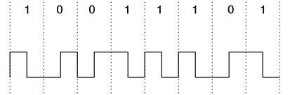
All the salt is that the bits are encoded not by the signal level, but by the transition between the levels in the middle of the period:

In addition this transition itself does not occur exactly in the middle of the period, but somewhere around:

As you can see, the period itself is 1ms -10% + 15% and the transition is somewhere in the middle.
This is where I stopped for a long time. There was no desire to copy something from the Internet, because each project has its own stumbling block, having decided that you feel not just a mindless copy-pasteurist of libraries, but a developer who makes this project. This, in fact, is the heart of the thermostat - working with OT, to copy it simply means to assemble another toy from the designer, and not to create something of your own.
It was here that I wanted to apply all my meager knowledge of MK - both interrupts and timers, etc. Yes, on delay () it’s all much easier, but, firstly, the transmission is too slow to receive it using delay (), but I wanted to perform other actions in parallel during reception / transmission, and secondly, I wanted everything looked decent, and not like a schoolboy’s crafts.
I thought, how beautiful it is to catch the very transition, and even whether it was a front or a recession, and as soon as I looked at it from a different angle, it all became crystal clear - why even understand what transition was ?! After all, the level of the first half of the period is the desired value of the bit:

There is a first step - to take the level of the first half of the period (somewhere 250 µs after the start) - that’s all decoding. But here the following disappointment awaited me - to catch the beginning of a period is not always possible: if there is a combination of 01 or 10, then nothing remarkable happens between periods, because obviously, the level does not change - you need to look further. And here is the second revelation - in the middle of the period ALWAYS a transition occurs - it is with them that 0 and 1 are encoded. So you can get attached to it, and the value of the next bit will be in half the period! Here, everything became completely clear.
Imagine that we have already accepted part of the bits and are located just in the middle of the first period:
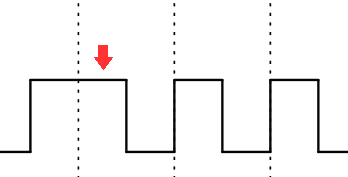
All you need to do is enable interrupt on a change in the input signal. As soon as this happens, then we are exactly in the middle of the period. Turn off the interrupt on changing the signal, reset the timer, and make the timer interrupt happen somewhere after ¾ period (which for the OT will be 750 μs), when the timer interrupt is triggered, record the input level, disable the timer interrupt, which is the desired bit and repeat all over again for all remaining bits.
The first case will be a special case, because wait for his level is not ¾ but ¼ period.
Interrupt handlers were quickly sketched and the firmware was assembled, but how can it be debugged without an oscilloscope and signal generator? Knowledge came to the rescue from the university - Proteus, in which you could step by step see what is happening.
I found, installed and here all the charms of practice went - it turns out that the interrupt flags need to be forced to be removed before the interrupt is turned on, and if you load OCR2A / B before changing the timer mode from FastPWM to CTC, then “such a cool slurry happened” (at first I thought it was an emulator glitch in the program, but as it turned out in the iron is still more fun). Well, and other little things that quickly decided. I remind you that at this stage I did not have iron, and I did not make specific requirements for the thermostat.
Here is the code fragment responsible for receiving the Manchester code:
inline void OpenTherm::receive(){
  cli();
  first=1;//receiving first bit
  buf=0;//clear buffer
  rx=1;
  data_ready=0;
  length=0;
  parity=0;
  PCICR|=bit(rx_pcie); //enabling Pin Change Interrupt for RX port
  *rx_pcmsk|=rx_bitmask; //enabling Pin Change Interrupt for RX pin of rx Port
  TCCR2A=bit(WGM21);//mode CTC
  TCCR2B=0;
  OCR2A=TICKS_PER_MS*0.75;//interrupt at 0.75ms
  TCNT2=TICKS_PER_MS*0.5;//preload 0.5ms
  TIMSK2=bit(OCIE2A);//interrupt on OC0A
  TIFR2=bit(OCF2A);
  sei();
bool OpenTherm::extIntHandler(){
  *rx_pcmsk&=~rx_bitmask; //Disable PCINT for RX pin
  if (first) {
    first=0;
  }
  else{
    TCNT2=0;
  }
  if (length > MSG_LENGTH){
    data_ready=1;
    TCCR2B=0;//disable Timer2
    TIMSK2=0;
    return 1;
  } else TCCR2B=bit(CS22); //start timer clk/64
	return 0;
};
void OpenTherm::timer2CompAHandler(){
  uint32_t tmp_buf;
  tmp_buf=buf;
  tmp_buf=tmp_buf<<1;
  if (rx) {
    if (*rx_port & rx_bitmask) { //Reading RX value
      tmp_buf=tmp_buf | 1;
      if (length > 1 ) parity^=1; //Don't calculate parity for start bit
    }
    *rx_pcmsk|=rx_bitmask; //Re-enabling PCINT for RX pin
    TCCR2B=0; //stop Timer2
  }
  length++;
  buf=tmp_buf;
};
}
The transfer, later, perfectly logically and practically fit into the same handlers.
Timer 2 works all in the same CTC mode with zeroing every millisecond. In the interrupt handler during zeroing (OC2A in CTC mode) we switch the output in accordance with the next bit. Additionally, the OC2B interrupt is activated, which triggers exactly half the period (0.5 ms) and inverts the output state. That's the whole wisdom of the transfer.
Here I assembled the interface circuit and in 3 hours I figured out the principle of its operation, which turned out to be quite simple, changed the circuit a bit to transmit data in a direct rather than inverted form, as in the original:

In addition, I had to write (well, how to write, take it from the Internet and change it for myself) the signal generator to HDL, because manually dial 34 bits in the Manchester code, this is not 4 or 5.
In the end, the reception / transmission was established, and it was time to determine the necessary equipment.
Equipment
So, I had a boiler (Ferolli Domiproject C24D) and firmware for receiving / transmitting OT messages in the Manchester code running in the emulator. It's time to move on.
What, first of all, is necessary for almost every device on the Arduino? Arduino itself? Wrong! An encoder, and always with a button, how else? It’s just that I was always attracted to this type of input device - you should definitely try it.
Next, the thermostat needs to get the temperature inside and outside - for these purposes 2 DS18B20 sensors are quite suitable, one should be filled with hot glue and put outside, the second will be on the board. Naturally, you need a display - without it, you can simply pour radio components into a jar, wrap it in a Silpo package and stop it - the effect is identical. I decided to take a standard character-generating LCD 20 * 4 - it would be quite enough, I2C port expander for LCD. The controller itself is quite enough Arduino Nano (now I would take the Pro Mini with the programmer, then I will tell you why). Well, a handful of details for the interface circuit.
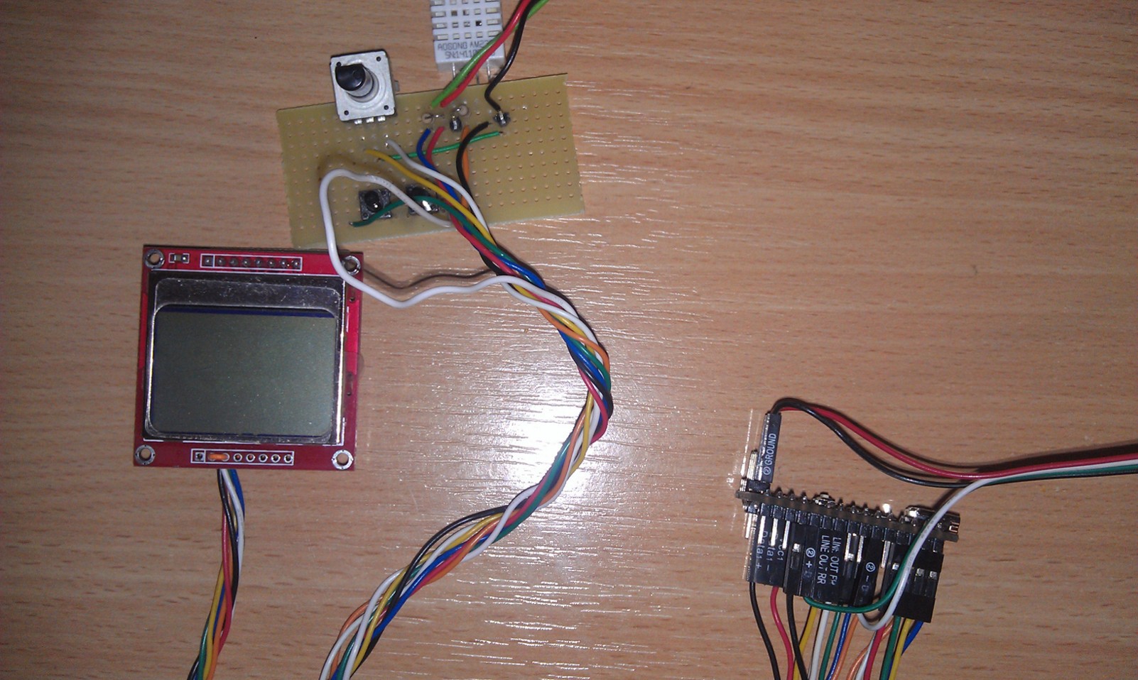
As you can see from the photo in the title, something went wrong. The seller had very attractive prices for everything, so I decided to slightly change the list. Instead of two DS18B20s, I took one in a waterproof case + DHT22, so now it will be possible to get more humidity in the room. LCD 20 * 4 was not available, and I took the display from Nokia 5110, there were no encoders with a button, so I took the usual + 2 buttons.
Upon receipt, everything was soldered and tested on test cases. First of all, we blink the LED (as I understand it when you first turn on the Arduino board, this is sacred). Everything worked as expected, so you can begin to improve.
Despite the presence of hardware SPI on the Atmega 328, I decided to abandon it, because the restrictions imposed by him were not very pleasing to me - MISO is automatically configured for input, and SS - must be an output - minus two outputs, and therefore leave the software SPI. I remove the CE display output control from the library and connect it directly to the GND directly on the LCD. I get - something like this: I
distribute the interface circuit in Proteus and try to repeat something similar on the breadboard:

At the end of the wire you can see the standard boiler terminal block, which turned out to be quite convenient - it connects and disconnects without the use of tools and removing the cover.
Well, now you can write a primitive firmware and try communication with the boiler. I am writing, flashing, connecting, and ... The
boiler works as it should, the article can be closed.
Trollface.jpg
Naturally nothing works.
I poke the tester into the interface card - it does not work - the input is always 20V. I disassemble, look, and smile. I soldered a payment to a friend. I immediately remembered the dialogue.
-Well, a lot more?
- No, it's almost done. Now solder this long track and that's it. The main thing is not to forget then to connect these two adjacent contacts.
Guess the first time that I forgot?
So the “Product” is fixed, connect, check. The levels are normal, you can connect the controller. Connecting - silence. All have arrived. There is nothing to do further without an oscilloscope. I’ll finish as the author of the first article. But there is still little hope.
We recall the part about the reception, namely, resetting the timer to a level change in the middle of the period. I thought, you never know, suddenly it’s not enough to zero and the timings of the incoming signal are generally a disaster, so I’ll turn it off before that at the moment of reading the level for a quarter of the period, and turn it on from zero from the change, oddly enough, it helped. It was that victory - without talking to MK even once before, writing from scratch a library that I could not find on the Internet, and even so that it worked the second time without an oscilloscope. My joy knew no bounds.
Slightly departing from the feeling of euphoria, I realized that I need to continue, because flashing the controller every time I need to read a new parameter (the test firmware in the cycle once a second read the same parameter) is probably not very user-friendly.
I learned how to get parameter values, only in this form it is not a thermostat, but a remote display. In order for this to become what is required, you need to learn how to control the boiler, and here, too, surprises awaited me.
Debugging and working with OpenTherm
So, the first value - the status of the boiler - is received. The only thing that immediately confused me was that the hot water temperature when connecting the microcontroller immediately became the maximum allowable, regardless of the settings on the boiler panel, as I later read in the manual to the standard OT thermostat from the manufacturer (Ferolli Romeo W): when connected, the handles only serve enable / disable the corresponding functions, and do not affect anything else. It was logical to assume that the value of the DHW temperature parameter will remain the same as it was before the OT connection, but Honeywell programmers (manufacturer of the board and the rest of the automation for the boiler) have their own opinion on this matter.
The process of controlling the boiler was complicated by the fact that I didn’t have a thermostat on my hands to see the correct sequence of messages, so it was like walking blindfolded. In the specification, the DHW Setpoint parameter was found (hereinafter in brackets I will give the DATA-ID of the called parameters, in this case - 56), which, apparently, was responsible for the temperature of the hot water supply. I’m shooting, stitching - now when I clicked on the button, the desired temperature was sent. Check, it is. The water temperature immediately became normal, it is time to start adjusting CH Setpoint (1) - the temperature of the heating circuit - for which everything was started. Here I am stuck for a long time, for three days. No matter how I tried, no matter what the required temperature was, the boiler still kept it at about 30 degrees. I already had an idea that the manufacturer protected itself from connecting foreign thermostats - the only obvious decision was to take Member-ID from the boiler (3) and answer it the same (2). And this also did not help, briefly outlined the situation to a friend, and he had an assumption:
- Listen, what if one vendor uses different Member-IDs for the master (thermostat) and slave (boiler) devices. Think about how surprised the automation of the boiler is when it realizes that it is controlled by another boiler?
But everything turned out to be much simpler. It was in the parameter Max CH Setpoint (57) - the maximum temperature of the heating circuit. After the events with the DHW circuit, it was logical to assume that there is a maximum value, but no, a value of 30 degrees was set there. After that, things went noticeably more fun.
This is where the story of the thermostat itself begins.
Thermostat
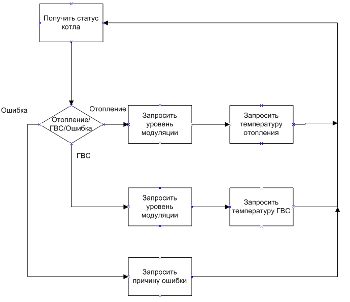
Obviously, he should give out a bunch of boiler parameters, and be able to change them, without this it would not make sense to create another thermostat. As I already said, each request should be sent approximately once a second, the most logical was to write a finite state machine that will go from one state to another once per cycle, and its states will correspond to the current requested parameters. In the end, the branches of the machine turned out 3:
1. The working branch, in which the current state of the boiler, temperature, modulation level is interrogated. Briefly, it can be represented as follows:
2. Information and boiler branch: additional temperature sensors, flow sensors, etc. When you exit the Info menu, we return to the first branch.
3. Branch of statistics: burner operating time, number of starts of fans / pumps, etc. Upon exit, identical to paragraph 2.
The call to the update () function, without parameters, is responsible for all this work. It is enough to call it about 1 time per second. She receives the result of the previous request and sends a new one based on it. To switch between branches, you need to call a function with a parameter that equals the first parameter of the desired branch. For example, update (0) will go to the main branch (0 - request for boiler status), update (18) - the second branch, which starts with request of parameter 18 (request for pressure in the heating circuit), branch 3 - parameter 116 (number of burner starts).
There are also other values of the argument:
1 - record the new temperature of the heating circuit;
56 - record the new temperature of the DHW circuit, etc.
All possible arguments are visible at the end of the update function.
So, all the required parameters are obtained, but there was a fly in the ointment - remember, I wrote after the table - all the other parameters at the request of the boiler manufacturer? So - half of them are zero in my boiler, half are not known at all. He wrote only in vain, although it might be useful to at least someone.
The most routine and boring occupation, obviously, was writing a menu. As promised, I will not go into details about the thermostat itself, everything can be seen in the final firmware
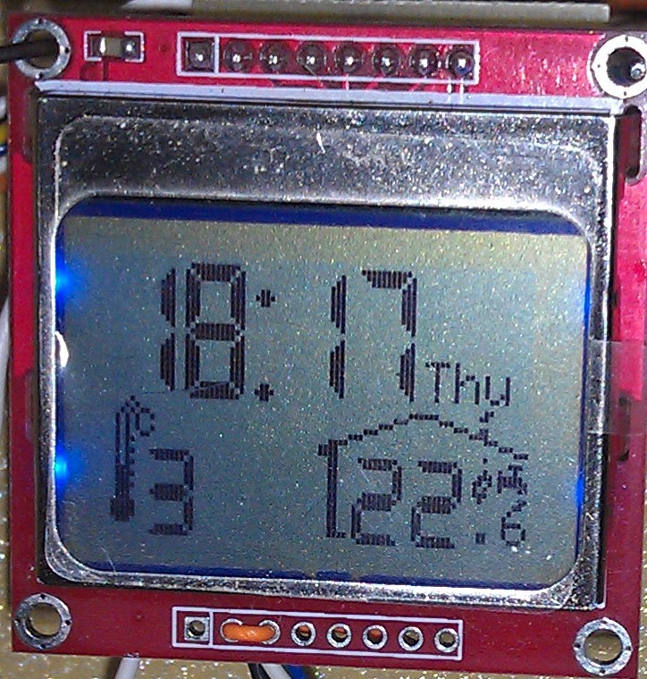
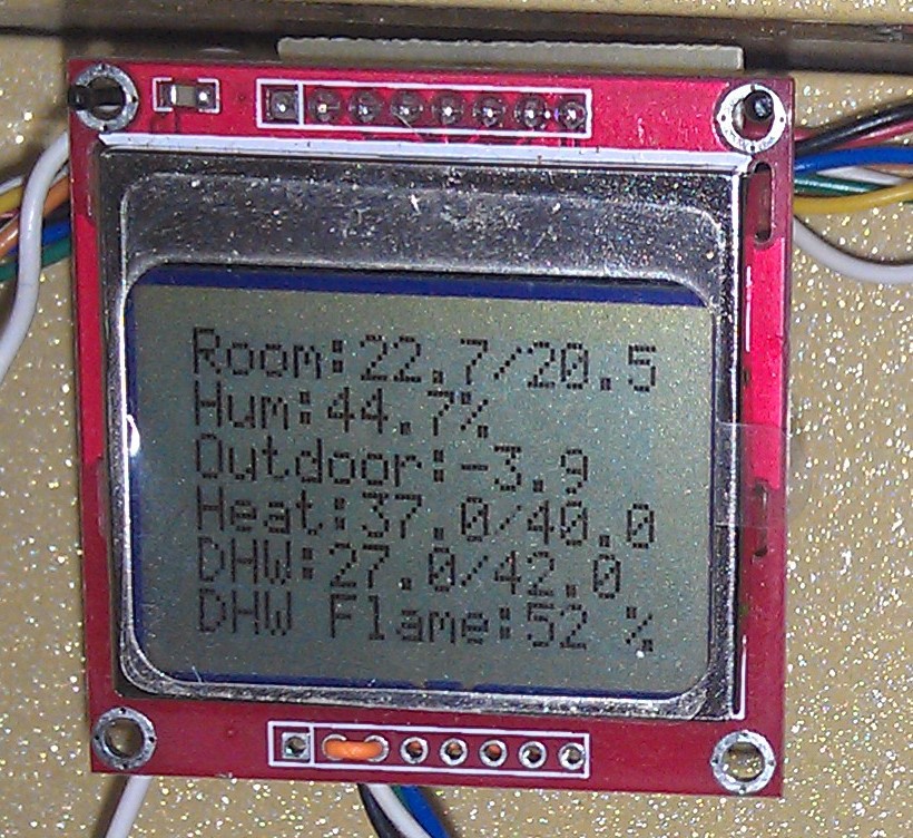
The last thing I decided to add while writing this article - instead of a boring screen with “a lot of letters”, I made a semblance of a graphic display (something similar to the model - factory Romeo W). Well, the clock - there aren’t many of them in the apartment, only the RTC DS323x is missing - when you turn off the power, you have to set the time again. To do this, I had to manually draw several characters and add them to the font. The result can be seen in the photo in the header and below.
Sketch
#include
#include
#include
#include
#include
#include
//#include
#define DHT22_PIN 14
#define LCD_IDLE 0
#define LCD_MAIN 1
#define LCD_MENU 2
#define LCD_CONFIG_1 11
#define LCD_CONFIG_2 12
#define LCD_CONFIG_3 13
#define LCD_INFO_1 21
#define LCD_INFO_2 22
#define LCD_STATISTICS_1 31
#define LCD_STATISTICS_2 32
#define LCD_ITEM_MODE 1
#define LCD_ITEM_CH_EN 2
#define LCD_ITEM_DHW_EN 3
#define LCD_ITEM_CH_MAX 4
#define LCD_ITEM_CH 5
#define LCD_ITEM_DHW 6
#define LCD_ITEM_ROOM 7
#define LCD_ITEM_BRIGH 8
#define LCD_ITEM_ACTIVE 9
#define LCD_ITEM_MAX_MODULATION 10
#define LCD_ITEM_DAYS 11
#define LCD_ITEM_HOURS 12
#define LCD_ITEM_MINUTES 13
#define LCD_ITEM_KP 14
#define LCD_ITEM_KI 15
dht internal_s;
OneWire ow(A1);
Dallastemp external_s(&ow);
OpenTherm ot(8,7);
LCD5110 lcd(13,11,10,12,0);
//Power sleep;
extern uint8_t SmallFont[];
extern uint8_t MediumNumbers[];
extern uint8_t BigNumbers[];
//Encoder handling
volatile uint32_t ts_enc=0;
volatile int8_t encoder=0;
//Clock handling
uint32_t clock_ts=0,clock_delta=0;
uint8_t hour=0,minute=0,second=0,day=0;
//Menu Handling
uint8_t menu,item;
int8_t pos=0;
const char* day_names[7]={"Mon","Tue","Wed","Thu","Fri","Sat","Sun"};
const char* mode_names[2]={"Manual","Auto"};
//Misc
uint8_t display_enabled,cfg_enabled,button1=0,button2=0,item_tmp=0,update_period=0;
float iSum;
struct thermostat_config{
  uint8_t address[8];
  ot_init_settings ot_settings;
  float indoor_target_temp;
  uint8_t active_time;
  uint8_t brightness;
  uint8_t mode;
  uint8_t Kp;
  uint8_t Ki;
  uint8_t reserved[8];
};
//thermostat_config settings={{0x28,0xFF,0x53,0x76,0x60,0x14,0x02,0xFC},{1,1,70,30.0,40},22.0,30,130,1};
thermostat_config settings;
/*
ISR(INT0_vect){
	ot.extIntHandler();
}
*/
ISR(PCINT0_vect){
	ot.extIntHandler();
}
ISR(PCINT1_vect){
	ot.extIntHandler();
}
ISR(PCINT2_vect){
	ot.extIntHandler();
}
ISR(TIMER2_COMPA_vect){
	ot.timer2CompAHandler();
}
ISR(TIMER2_COMPB_vect){
	ot.timer2CompBHandler();
}
ISR(WDT_vect)
{
//  sleep.watchdogEvent();
}
ISR(INT1_vect){
    display_enabled=settings.active_time;
    OCR1A=settings.brightness;
  if((millis()-ts_enc >20) && cfg_enabled) {
    ts_enc=millis();
    if ((PIND&bit(4))) {
      encoder++;
    }
    else {
      encoder--;
    }
  }
}
void fade_display(){
  for(uint8_t i=settings.brightness;i>10;i-=10){
    OCR1A=i;
    delay(20);
  }
  OCR1A=0;
}
void enc_setup(){
  cli();
  DDRD&=~(bit(3)|bit(4)); //set A and B to input
  EIMSK|=bit(INT1);
  EICRA|=bit(ISC11);
  EICRA&=~bit(ISC10);
  EIFR|=bit(INTF1);
  sei();
}
void button_setup(){
  DDRC&=~(bit(2)|bit(3));
}
void read_config(){
  eeprom_read_block(&settings, 0, sizeof(thermostat_config));
}
void write_config(){
  eeprom_write_block(&settings, 0, sizeof(thermostat_config));
}
void lcd_idle(){
  char mod_lev[2]={'\0','\0'};
  lcd.setFont(BigNumbers);
  lcd.print(":",24,0);
  lcd.print(";",0,24);//";" - thermometer icon
  lcd.print("0",0,0);
  lcd.print("0",34,0);
  lcd.print("<=>",42,24);//"<=>" - House icon
  lcd.printNumI(hour,(hour>9)?0:14,0);
  lcd.printNumI(minute,(minute>9)?34:48,0);
  lcd.setFont(SmallFont);
  lcd.print(day_names[day],62,16);
  lcd.printNumF(internal_s.temperature,1,60,40);
  switch(ot.status&0x7){
    case OT_STATUS_CH: lcd.print(">",78,32);
      break;
    case OT_STATUS_DHW: lcd.print("=",78,32);
      break;
    case OT_STATUS_FAULT: lcd.print("?@",72,32);
      break;
  };
  if (ot.status&0x8){
   if (ot.modulation < 34) *mod_lev='^';
   else if (ot.modulation < 67) *mod_lev='_';
        else *mod_lev='`';
   lcd.print(mod_lev,72,32);
  }
  lcd.setFont(MediumNumbers);
  lcd.printNumF(external_s.getTemp(settings.address),0,6,32);
  lcd.printNumI(internal_s.temperature,48,32);
}
void lcd_main(){
  lcd.print("Room:    /",LEFT,0);
  lcd.printNumF(internal_s.temperature,1,30,0);
  if (settings.mode) lcd.printNumF(settings.indoor_target_temp,1,60,0);
  else lcd.print("    ",54,0);
  lcd.print("Hum:    \%",LEFT,8);
  lcd.printNumF(internal_s.humidity,1,24,8);
  lcd.print("Outdoor:",LEFT,16);
  lcd.printNumF(external_s.getTemp(settings.address),1,48,16);
  lcd.print("Heat:    /",LEFT,24);
  lcd.printNumF(ot.CH,1,30,24);
  lcd.printNumF(settings.ot_settings.CH_temp,1,60,24);
  lcd.print("DHW:    /",LEFT,32);
  lcd.printNumF(ot.DHW,1,24,32);
  lcd.printNumF(ot.target_DHW,1,54,32);
  switch(ot.status&0x7){
    case OT_STATUS_CH:
      lcd.print("CH  ",LEFT,40);
      break;
    case OT_STATUS_DHW:
      lcd.print("DHW ",LEFT,40);
      break;
    case OT_STATUS_FAULT:
      lcd.print("FAULT:",LEFT,40);
      switch(ot.fault&0x3D){
        case OT_FAULT_SERVICE:
        lcd.print("FAULT:SERV REQ",LEFT,40);
        break;
        case OT_FAULT_LOW_WATER:
        lcd.print("FAULT:NO WATER",LEFT,40);
        break;
        case OT_FAULT_GAS:
        lcd.print("FAULT:NO FLAME",LEFT,40);
        break;
        case OT_FAULT_AIR_PRESSURE:
        lcd.print("FAULT:AIR PRES",LEFT,40);
        break;
        case OT_FAULT_WATER_OV_TEMP:
        lcd.print("FAULT:WATER OT",LEFT,40);
        break;
      }
      break;
    default:
      lcd.print("              ",LEFT,40);
      break;
  };
  if (ot.status&0x8) {
   lcd.print("Flame:   %",24,40);
   lcd.printNumI(ot.modulation,60,40);
  }
}
void lcd_menu(){
  lcd.print(" 1)Config",LEFT,0);
  lcd.print(" 2)Info",LEFT,8);
  lcd.print(" 3)Stats",LEFT,16);
}
void lcd_config_1(){
  lcd.print(" Mode:",LEFT,0);
  lcd.print(mode_names[(item==LCD_ITEM_MODE)?item_tmp:settings.mode],RIGHT,0);
  lcd.print(" CH enabled:",LEFT,8);
  lcd.printNumI((item==LCD_ITEM_CH_EN)?item_tmp:ot.CH_enabled,RIGHT,8);
  lcd.print(" DHW enabled:",LEFT,16);
  lcd.printNumI((item==LCD_ITEM_DHW_EN)?item_tmp:ot.DHW_enabled,RIGHT,16);
  lcd.print(" CH max t:",LEFT,24);
  lcd.printNumI((item==LCD_ITEM_CH_MAX)?item_tmp:ot.CH_max,RIGHT,24);
  lcd.print(" CH temp:",LEFT,32);
  lcd.printNumI((item==LCD_ITEM_CH)?item_tmp:ot.target_CH,RIGHT,32);
  lcd.print(" DHW temp:",LEFT,40);
  lcd.printNumI((item==LCD_ITEM_DHW)?item_tmp:ot.target_DHW,RIGHT,40);
}
void lcd_config_2(){
  lcd.print(" Room temp:",LEFT,0);
  lcd.printNumF((item==LCD_ITEM_ROOM)?(float)item_tmp/10+10:settings.indoor_target_temp,1,RIGHT,0);
  lcd.print(" Brightness:",LEFT,8);
  lcd.printNumI((item==LCD_ITEM_BRIGH)?item_tmp:settings.brightness,RIGHT,8);
  lcd.print(" Light time:",LEFT,16);
  lcd.printNumI((item==LCD_ITEM_ACTIVE)?item_tmp:settings.active_time,RIGHT,16);
  lcd.print(" Max modul:",LEFT,24);
  lcd.printNumI((item==LCD_ITEM_MAX_MODULATION)?item_tmp:settings.ot_settings.max_modulation,RIGHT,24);
  lcd.print(" Days:",LEFT,32);
  lcd.print(day_names[(item==LCD_ITEM_DAYS)?item_tmp:day],RIGHT,32);
  lcd.print(" Hours:",LEFT,40);
  lcd.printNumI((item==LCD_ITEM_HOURS)?item_tmp:hour,RIGHT,40);
}
void lcd_config_3(){
  lcd.print(" Minutes",LEFT,0);
  lcd.printNumI((item==LCD_ITEM_MINUTES)?item_tmp:minute,RIGHT,0);
  lcd.print(" Kp",LEFT,8);
  lcd.printNumI((item==LCD_ITEM_KP)?item_tmp:settings.Kp,RIGHT,8);
  lcd.print(" Ki",LEFT,16);
  lcd.printNumI((item==LCD_ITEM_KI)?item_tmp:settings.Ki,RIGHT,16);
}
void lcd_info_1(){
  lcd.print(" CH press:",LEFT,0);
  lcd.printNumF(ot.CH_water_pressure,1,RIGHT,0);
  lcd.print(" DHW flow:",LEFT,8);
  lcd.printNumF(ot.DHW_flow,1,RIGHT,8);
  lcd.print(" Ret.temp:",LEFT,16);
  lcd.printNumF(ot.CH_return_temp,1,RIGHT,16);
  lcd.print(" Max cap.:",LEFT,24);
  lcd.printNumI(ot.max_capacity,RIGHT,24);
  lcd.print(" Min mod.:",LEFT,32);
  lcd.printNumI(ot.min_modulation,RIGHT,32);
  lcd.print(" DHW min lim:",LEFT,40);
  lcd.printNumI(ot.DHW_min_lim,RIGHT,40);
}
void lcd_info_2(){
  lcd.print(" DHW lim:",LEFT,0);
  lcd.printNumI(ot.DHW_max_lim,RIGHT,0);
  lcd.print(" CH lim:",LEFT,8);
  lcd.printNumI(ot.CH_min_lim,RIGHT,8);
  lcd.print(" CH lim:",LEFT,16);
  lcd.printNumI(ot.CH_max_lim,RIGHT,16);
  lcd.print(" Int.Sum.:",LEFT,24);
  lcd.printNumF(iSum,1,RIGHT,24);
}
void lcd_stats_1(){
  lcd.print(" Burn.st:",LEFT,0);
  lcd.printNumI(ot.burner_starts,RIGHT,0);
  lcd.print(" CH pump:",LEFT,8);
  lcd.printNumI(ot.CH_pump_starts,RIGHT,8);
  lcd.print(" DHW p/v:",LEFT,16);
  lcd.printNumI(ot.DHW_pump_starts,RIGHT,16);
  lcd.print(" DHW bur:",LEFT,24);
  lcd.printNumI(ot.DHW_burner_starts,RIGHT,24);
  lcd.print(" B.hours:",LEFT,32);
  lcd.printNumI(ot.burner_op_hours,RIGHT,32);
  lcd.print(" CHpump H",LEFT,40);
  lcd.printNumI(ot.CH_pump_op_hours,RIGHT,40);
}
void lcd_stats_2(){
  lcd.print(" DHWp/v H",LEFT,0);
  lcd.printNumI(ot.DHW_pump_op_hours,RIGHT,0);
  lcd.print(" DHWburn H",LEFT,8);
  lcd.printNumI(ot.DHW_burner_op_hours,RIGHT,8);
}
void update_clock(){
  uint32_t tmp=millis()-clock_ts;
  clock_delta+=(tmp>0)?tmp:0;
  clock_ts=millis();
  while (clock_delta >= 1000){
    second++;
    clock_delta-=1000;
    if (second > 59){
      second=0;
      minute++;
      if (minute > 59){
        minute=0;
        hour++;
        if (hour > 23){
          hour=0;
          day++;
        if (day>6) day=0;
        }
      }
    }
  }
}
void update_display(){
  lcd.clrScr();
  lcd.setFont(SmallFont);
  if (menu != LCD_MAIN && menu != LCD_IDLE) {
    if (pos>5){
      pos=0;
      switch(menu){
        case LCD_INFO_1: menu=LCD_INFO_2;
        break;
        case LCD_STATISTICS_1: menu=LCD_STATISTICS_2;
        break;
        case LCD_CONFIG_1: menu=LCD_CONFIG_2;
        break;
        case LCD_CONFIG_2: menu=LCD_CONFIG_3;
        break;
      default: pos=5;
      }
    }
    if (pos<0){
      pos=5;
        switch(menu){
        case LCD_INFO_2: menu=LCD_INFO_1;
        break;
        case LCD_STATISTICS_2: menu=LCD_STATISTICS_1;
        break;
        case LCD_CONFIG_2: menu=LCD_CONFIG_1;
        break;
        case LCD_CONFIG_3: menu=LCD_CONFIG_2;
        break;
        default: pos=0;
      }
    }
   };
  switch(menu){
    case LCD_IDLE: lcd_idle();
    break;
    case LCD_MAIN: lcd_main();
    break;
    case LCD_MENU: lcd_menu();
    break;
    case LCD_CONFIG_1: lcd_config_1();
    break;
    case LCD_CONFIG_2: lcd_config_2();
    break;
    case LCD_CONFIG_3: lcd_config_3();
    break;
    case LCD_INFO_1: lcd_info_1();
    break;
    case LCD_INFO_2: lcd_info_2();
    break;
    case LCD_STATISTICS_1: lcd_stats_1();
    break;
    case LCD_STATISTICS_2: lcd_stats_2();
    break;
  };
   if (menu != LCD_IDLE && menu != LCD_MAIN)
     if(! item)  lcd.print("\\",LEFT,pos*8);
      else  lcd.print("*",LEFT,pos*8);
}
void setup(){
  lcd.InitLCD();
  lcd.setFont(SmallFont);
  lcd.clrScr();
  enc_setup();
  button_setup();
  read_config();
  //sleep.measure_wdt(1);
 // external_s.setRes(settings.address,TEMP_11_BIT);
 // external_s.startConv(settings.address);
  analogWrite(9,settings.brightness);
  display_enabled=settings.active_time;
  lcd.print("OT init.",CENTER,16);
  ot.begin(&settings.ot_settings);
  //sleep.measure_wdt(0);
  lcd.clrScr();
  lcd.print("Slave OT ver.:",CENTER,0);
  lcd.printNumF(ot.slave_ver,1,CENTER,8);
  lcd.print("Slave Memb. ID:",CENTER,16);
  lcd.printNumI(ot.member_id,CENTER,24);
  lcd.print("Slave CFG:",CENTER,32);
  lcd.printNumI(ot.sl_cfg,CENTER,40);
}
void loop(){
  //DEBUG
  //uint8_t type=0,id=0;
  //uint16_t data=0;
  float ext_temp,int_temp,t_error;
  if (!update_period) {
    internal_s.read22(DHT22_PIN);
    external_s.startConv(settings.address);
  }
  if(display_enabled){
    OCR1A=settings.brightness;
    if(! --display_enabled) {
      fade_display();
      cfg_enabled=0;
      menu=LCD_IDLE;
      item=0;
      delay(1000);
      ot.update(0); //main thread
      update_display();
    }
  }
  if (cfg_enabled) delay (100);
  else delay(1000); //sleep 1s here
 // else sleep.sleep();
  if (cfg_enabled || !update_period) {
        update_display();
  }
   if ( (PINC&bit(2)) &&  button1) button1=0; //if button released reset state
   if ( (PINC&bit(3)) &&  button2) button2=0;
 //Esc
    if (! (PINC&bit(2)) && ! button1) {
      button1=1;
      display_enabled=settings.active_time;
      OCR1A=settings.brightness;
      cfg_enabled=1;
      switch(menu){
        case LCD_IDLE: menu=LCD_MAIN;
        break;
        case LCD_MAIN:
          if ((ot.status&0x7) == OT_STATUS_FAULT) {
            delay(1000);
            ot.communicate(1,4,256);
          }
        break;
        case LCD_MENU: menu=LCD_MAIN;
        break;
        case LCD_CONFIG_1:
        case LCD_CONFIG_2:
        case LCD_CONFIG_3:
          if(! item) menu=LCD_MENU;
          else item=0;
        break;
        default: menu=LCD_MENU;
        break;
      };
      pos=0;
  }
  //Enter
    if (! (PINC&bit(3)) && ! button2) {
      button2=1;
      display_enabled=settings.active_time;
      OCR1A=settings.brightness;
      cfg_enabled=1;
      if (! item){ //standart menu navigation
      switch(menu){
        case LCD_IDLE:
        case LCD_MAIN: menu=LCD_MENU;
        break;
        case LCD_MENU:
          switch(pos){
           case 0: menu=LCD_CONFIG_1;
           break;
           case 1:
              menu=LCD_INFO_1;
              delay(1000);
              ot.update(18); //start to get info
           break;
           case 2:
              menu=LCD_STATISTICS_1;
              delay(1000);
              ot.update(116); //start to get stats
           break;
          }
        break;
        case LCD_CONFIG_1:
          if (!item) item=pos+1;
        case LCD_CONFIG_2:
          if (!item) item=pos+7;
        case LCD_CONFIG_3:
          if (!item) item=pos+13;
           switch(item){
            case LCD_ITEM_MODE: item_tmp=settings.mode;
            break;
            case LCD_ITEM_CH_EN: item_tmp=ot.CH_enabled;
            break;
            case LCD_ITEM_DHW_EN: item_tmp=ot.DHW_enabled;
            break;
            case LCD_ITEM_CH_MAX: item_tmp=ot.CH_max;
            break;
            case LCD_ITEM_CH: item_tmp=settings.ot_settings.CH_temp;
            break;
            case LCD_ITEM_DHW: item_tmp=ot.target_DHW;
            break;
            case LCD_ITEM_ROOM: item_tmp=(uint8_t)(settings.indoor_target_temp*10 - 100);
            break;
            case LCD_ITEM_BRIGH: item_tmp=settings.brightness;
            break;
            case LCD_ITEM_ACTIVE: item_tmp=settings.active_time;
            break;
            case LCD_ITEM_MAX_MODULATION: item_tmp=settings.ot_settings.max_modulation;
            break;
            case LCD_ITEM_DAYS: item_tmp=day;
            break;
            case LCD_ITEM_HOURS: item_tmp=hour;
            break;
            case LCD_ITEM_MINUTES: item_tmp=minute;
            break;
            case LCD_ITEM_KP: item_tmp=settings.Kp;
            break;
            case LCD_ITEM_KI: item_tmp=settings.Ki;
            break;
      }
        break;
        case LCD_INFO_1:
        break;
        case LCD_INFO_2:
        break;
      };
      if (!item) pos=0;
    } else { //item save
      switch(item){
        case LCD_ITEM_MODE:
          settings.mode=item_tmp;
        break;
        case LCD_ITEM_CH_EN:
          ot.CH_enabled=item_tmp;
          settings.ot_settings.CH_enabled=item_tmp;
        break;
        case LCD_ITEM_DHW_EN:
          ot.DHW_enabled=item_tmp;
          settings.ot_settings.DHW_enabled=item_tmp;
        break;
        case LCD_ITEM_CH_MAX:
          ot.CH_max=item_tmp;
          settings.ot_settings.CH_max_temp=item_tmp;
          delay(1000);
          ot.update(57);
        break;
        case LCD_ITEM_CH:
          settings.ot_settings.CH_temp=item_tmp;
          ot.target_CH=item_tmp;
          delay(1000);
          ot.update(1);
        break;
        case LCD_ITEM_DHW:
          ot.target_DHW=item_tmp;
          settings.ot_settings.DHW_temp=item_tmp;
          delay(1000);
          ot.update(56);
        break;
        case LCD_ITEM_ROOM: settings.indoor_target_temp=(float)item_tmp/10+10.0;
        break;
        case LCD_ITEM_BRIGH: settings.brightness=item_tmp;
        break;
        case LCD_ITEM_ACTIVE: settings.active_time=item_tmp;
        break;
        case LCD_ITEM_MAX_MODULATION:
          ot.max_modulation=item_tmp;
          settings.ot_settings.max_modulation=item_tmp;
          delay(1000);
          ot.update(14);
        break;
        case LCD_ITEM_DAYS: day=item_tmp;
        break;
        case LCD_ITEM_HOURS: hour=item_tmp;
        break;
        case LCD_ITEM_MINUTES: minute=item_tmp;
        break;
        case LCD_ITEM_KP: settings.Kp=item_tmp;
        break;
        case LCD_ITEM_KI: settings.Ki=item_tmp;
        break;
      }
      write_config();
      item_tmp=0;
      item=0;
    }
    }
/*
ot.complete(&type,&id,&data);
    lcd.setFont(SmallFont);
    lcd.print(" /   /",LEFT,40);
    lcd.printNumI(type,0,40);
    lcd.printNumI(id,12,40);
    lcd.printNumI(data,36,40);
//debug
*/
 if (encoder !=0 ) {
    if (menu != LCD_MAIN)
     if(!item) pos=constrain(pos+encoder,-1,6);
     else
       switch (item){
        case LCD_ITEM_MODE: item_tmp=constrain(item_tmp+encoder,0,1);
        break;
        case LCD_ITEM_CH_EN: item_tmp=constrain(item_tmp+encoder,0,1);
        break;
        case LCD_ITEM_DHW_EN: item_tmp=constrain(item_tmp+encoder,0,1);
        break;
        case LCD_ITEM_CH_MAX: item_tmp=constrain(item_tmp+encoder,ot.CH_min_lim,ot.CH_max_lim);
        break;
        case LCD_ITEM_CH: item_tmp=constrain(item_tmp+encoder,ot.CH_min_lim,ot.CH_max_lim);
        break;
        case LCD_ITEM_DHW: item_tmp=constrain(item_tmp+encoder,ot.DHW_min_lim,ot.DHW_max_lim);
        break;
        case LCD_ITEM_ROOM: item_tmp=constrain(item_tmp+encoder,50,180);
        break;
        case LCD_ITEM_BRIGH: item_tmp=constrain(item_tmp+encoder*10,0,255);
        break;
        case LCD_ITEM_ACTIVE: item_tmp=constrain(item_tmp+encoder,10,100);
        break;
        case LCD_ITEM_MAX_MODULATION: item_tmp=constrain(item_tmp+encoder,10,100);
        break;
        case LCD_ITEM_DAYS: item_tmp=constrain(item_tmp+encoder,0,6);
        break;
        case LCD_ITEM_HOURS: item_tmp=constrain(item_tmp+encoder,0,23);
        break;
        case LCD_ITEM_MINUTES: item_tmp=constrain(item_tmp+encoder,0,59);
        break;
        case LCD_ITEM_KP:
        case LCD_ITEM_KI: item_tmp=constrain(item_tmp+encoder,0,255);
        break;
 item_tmp=constrain(item_tmp+encoder,0,255);
        break;
      } else
          if (settings.mode)
            settings.indoor_target_temp=constrain(settings.indoor_target_temp+encoder*0.1,15.0,28.0);
          else settings.ot_settings.CH_temp+=encoder*0.1;
    encoder=0;
  };
  if (menu == LCD_IDLE && ! cfg_enabled && !update_period--) {
    update_period=60;
    update_clock();
    int_temp=internal_s.temperature;
    ext_temp=external_s.getTemp(settings.address);
    t_error=settings.indoor_target_temp-int_temp;
    iSum=constrain(iSum+t_error,-ot.CH_max_lim,ot.CH_max_lim);
    if (settings.mode) settings.ot_settings.CH_temp=1*(20.0 + (settings.indoor_target_temp-ext_temp)) + settings.Kp*t_error + settings.Ki*iSum/256;
    if (settings.ot_settings.CH_temp < ot.CH_min_lim) ot.CH_enabled=0;
    else ot.CH_enabled = 1;
    settings.ot_settings.CH_temp=constrain(settings.ot_settings.CH_temp,ot.CH_min_lim,ot.CH_max_lim);
    if  ((!settings.mode && ot.target_CH != settings.ot_settings.CH_temp ) || (settings.mode && abs(ot.target_CH - settings.ot_settings.CH_temp) > 0.5)){
      ot.target_CH=settings.ot_settings.CH_temp;
    //  delay(1000);
      ot.update(1);
      return;
    }
  }
  ot.update();
}
For a long time I turned the formula for calculating the required coolant temperature-output, until, as a result, it turned out to be a PI regulator. In the settings I added a change in the coefficients and an indication of the integral component. Prior to the PI controller, to calculate the required temperature, I took the formula from the first article, but without the integral component, the temperature either did not correspond to the required one, or, with a large proportional coefficient, did not correspond to the required one and jumped back and forth. But reading Habr quickly gave me a link with a description of the PID controller, which was implemented.
In general, I made two modes of operation:
1) Direct control of CH Setpoint - the result is nothing more than a remote front panel of the boiler (well, plus it also shows the temperature outside / inside and humidity).
2) Actually thermostat with OTC.
Perhaps I will also add turning off the OTC sensor and adjusting the slope of the curve (coefficient at (settings.indoor_target_temp-ext_temp)), but I don’t see the point in this yet.
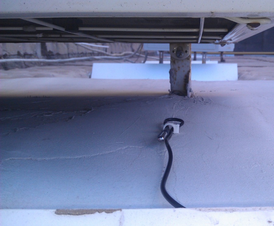
I’ll add a few words about the placement of the OTC sensor. I did not want to drill holes in windows and walls, and, thinking about this problem, my eyes accidentally fell on the old loop of the MIDI connector. Without thinking twice, I soldered the sensor wire and sealed the junction with hot-melt adhesive (since it will be on the street). I placed the sensor itself in the shade behind the external unit of the air conditioner, so that it would not be heated by direct sunlight.
OTC installation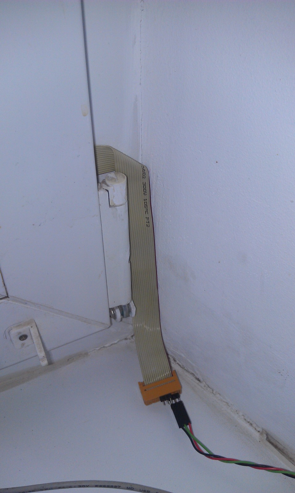

Energy saving
Those who leafed through the code a little more carefully probably noticed the unknown Power library. Actually, I had hopes for reducing the energy consumption of the entire device. The point is, instead of delay (1000) in the main loop, send MK to sleep for 1s. The problem is that you need a specific sleep mode, with running Timer2 to send / receive OpenTherm messages, as you remember, they occur asynchronously. But alas, Proteus does not work very well with Sleep, and I could not debug this part. The sleep is working, the millis () readings are corrected (for this I implemented a measurement of the accuracy of the watchdog timer), but the OT stops working. It was for this purpose that I wanted to purchase the Pro Mini (with the subsequent removal of the stabilizer and LEDs) - a smaller board + 3.3V operation is possible, which gives hope for power supply directly from the OT interface. I bring the Power library code,
Power.h
#include
#include
#include
class Power{
  private:
    uint16_t wdt_delay;
    volatile uint32_t ts,delta;
    volatile uint8_t wdt_count;
    uint8_t calibration;
   public:
     void watchdogEvent();
     void prepare_wdt();
     void measure_wdt(uint8_t);
     void sleep();
};
Power.cpp
#include "Power.h"
void Power::watchdogEvent(){
 if (calibration) {
  delta+=millis()-ts;
  ts=millis();
   }else wdt_disable();
  wdt_count++;
}
void Power::prepare_wdt(){
  wdt_reset();
  WDTCSR|=1<
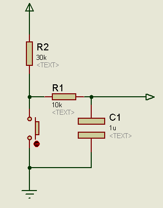
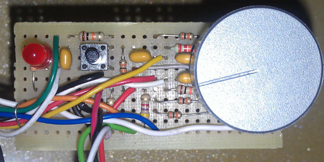
В процессе написания статьи, я значительно переписал код и переделал управление – поставил энкодер с кнопкой, добавил ему ручку, сделал аппаратный фильтр дребезга по классической схеме:
Стало значительно лучше – энкодер перестал проскакивать такты и добавлять лишние значения. Да и новая панель управления стала поудобнее, и должна ровно встать в корпус:
Дело осталось за самым малым – сделать корпус и повесить на место, но в этом и кроется самая большая проблема. Оказывается стоимость корпусов, отпечатанных на 3D-принтере, вплотную приближается к стоимости всего термостата, что совсем не радует мою ручную жабу, стоимость готовых радиолюбительских корпусов тоже не сильно адекватная для куска пластмассы. Наверное придется поступить, как подсказал друг:
— А ты знаешь, какие корпуса испокон веков лучше всего подходили для радиолюбительских поделок?
— Никакие?
— Тоже, конечно, вариант, но вообще – мыльницы.
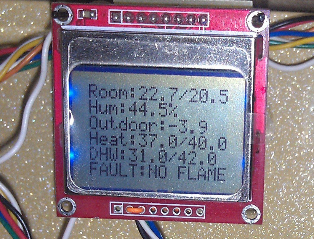
Немного фото термостата во время испытаний и показаний в разных режимах на главном экране:
Фото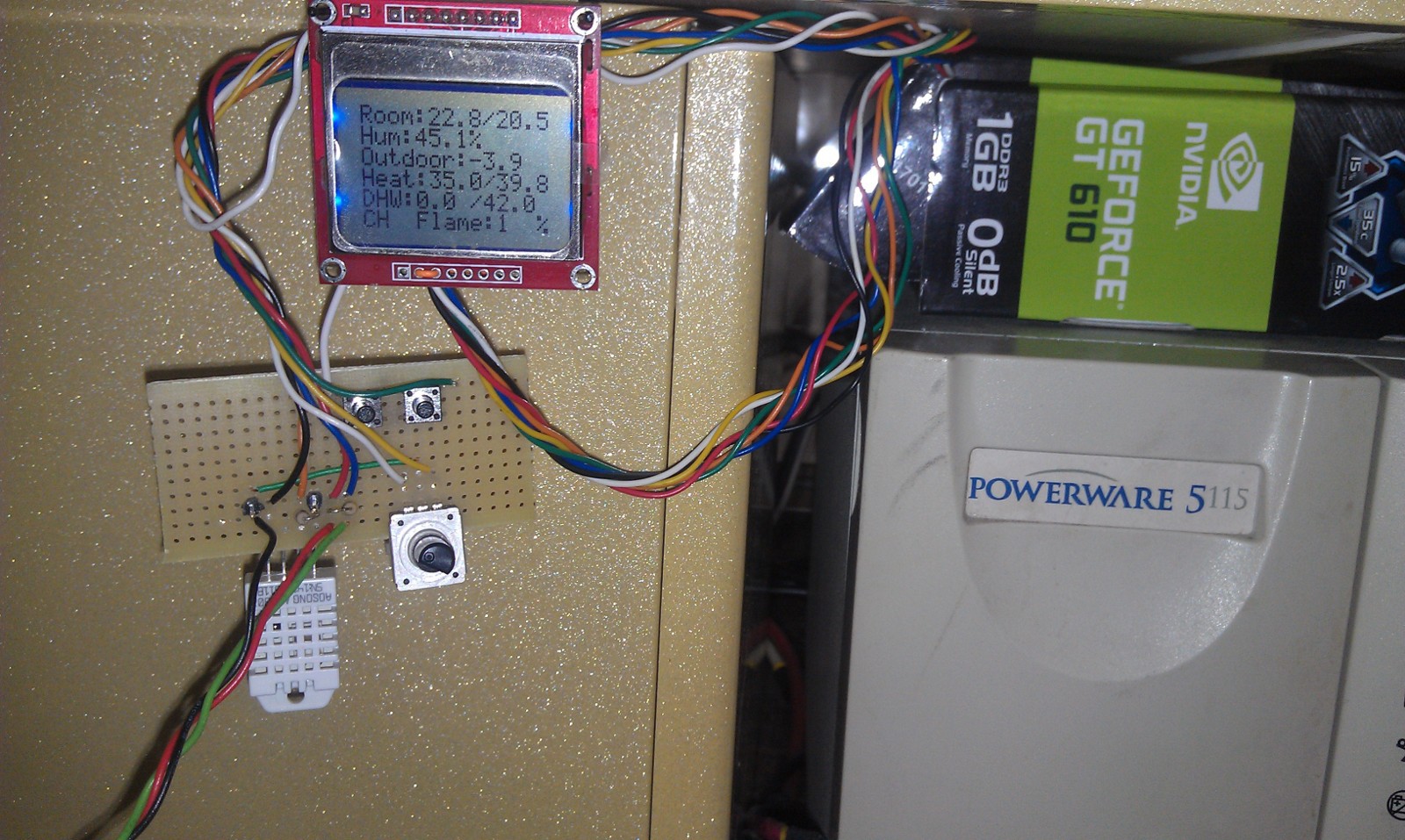
Коды графических символов6x8:
0x98, 0x3c, 0x66, 0x99, 0x7e, 0x30, // Пламя
0x3c, 0x18, 0x1a, 0x1e, 0xba, 0xb0, // Кран (иконка ГВС)
0x04, 0xfd, 0x84, 0xfd, 0x84, 0xfd, //Батарея (иконка отопления)
0x00, 0xe0, 0x90, 0x8c, 0x82, 0xdd, //Восклицательный знак в треугольнике (левая половинка)
0xdd, 0x82, 0x8c, 0x90, 0xe0, 0x00, //Правая половинка
0x00, 0x60, 0xf0, 0x7a, 0x20, 0x00, //Маленькое пламя
0x00, 0x70, 0xd8, 0x6d, 0x18, 0x00, //Среднее пламя
0x0c, 0x72, 0xdb, 0x6c, 0x1b, 0x06, //Большое пламя
24x14:
0x00, 0xf8, 0x04, 0xfa, 0x85, 0x3a, 0x44, 0x44, 0x28, 0x00, 0x00, 0x00, 0x00, 0x00, 0x00, 0xff, 0xf0, 0xff, 0xAA, 0x00, 0x00, 0x00, 0x00, 0x00, 0x00, 0x00, 0x00, 0x00, 0x1c, 0x3f, 0x3f, 0x3f, 0x1c, 0x00, 0x00, 0x00, 0x00, 0x00, 0x00, 0x00, 0x00, 0x00, //Термометр
0x80, 0x80, 0xc0, 0xc0, 0x40, 0x40, 0x20, 0x20, 0x20, 0x10, 0x10, 0x10, 0x08, 0x08, 0x01, 0x01, 0xff, 0xff, 0x00, 0x00, 0x00, 0x00, 0x00, 0x00, 0x00, 0x00, 0x00, 0x00, 0x00, 0x00, 0x7f, 0x7f, 0x40, 0x40, 0x00, 0x00, 0x00, 0x00, 0x00, 0x00, 0x00, 0x00, //Левая треть дома
0x08, 0x04, 0x04, 0x04, 0x02, 0x02, 0x02, 0x02, 0x02, 0x02, 0x04, 0x04, 0x04, 0x08, 0x00, 0x00, 0x00, 0x00, 0x00, 0x00, 0x00, 0x00, 0x00, 0x00, 0x00, 0x00, 0x00, 0x00, 0x00, 0x00, 0x00, 0x00, 0x00, 0x00, 0x00, 0x00, 0x00, 0x00, 0x00, 0x00, 0x00, 0x00, //Центральная
0x08, 0x08, 0x10, 0x10, 0x1a, 0x3b, 0x21, 0x20, 0x40, 0x40, 0x40, 0x80, 0x80, 0x80, 0x00, 0x00, 0x00, 0x00, 0x00, 0x00, 0x00, 0x00, 0x00, 0x00, 0x00, 0x00, 0x00, 0x00, 0x00, 0x00, 0x00, 0x00, 0x00, 0x00, 0x00, 0x00, 0x00, 0x00, 0x00, 0x00, 0x00, 0x00, //Правая
Для тех, кто будет использовать библиотеку, хочу обратить внимание, что вы можете не использовать функцию update(), а работать на прямую с котлом используя свои команды как вам захочется, используя функции communicate() — отправка запроса и complete() — чтение ответа
Ссылки
github.com/gavrilov-i/OpenTherm
habrahabr.ru/post/214257
otgw.tclcode.com
www.domoticaforum.eu/uploaded/Ard%20M/Opentherm%20Protocol%20v2-2.pdf
P.S. Ну и, естественно, прошу строго не судить – я не писатель — ошибки проверил, как мог. А результатом просто решил поделиться с публикой, т.к. больше рабочих библиотек, реализующих протокол OpenTherm, я в интернете не нашел.
P.P.S. В личку поступило много вопросов по поводу распиновки платы сопряжения, действительно не заметил своей оплошности. Итак, сверху вниз — +5В, TX (от контроллера к котлу), RX (от котла к контроллеру) — резистор 1,5к, GND.
Касательно проверки платы сопряжения:
Плату сопряжения проверить не сложно — подключаете к котлу, подаете питание. Вывод RX не используете(если есть лог. анализатор то будет проще потом) вывод TX (после R3) на +5В. На контактах к котлу должно быть около 20В. после этого вывод R3 на землю — должно быть меньше 7В (около 5ти). Это значит, что плата на передачу работает нормально. На прием можно проверить только после прошивки МК.