CNC milling machine with standalone controller on STM32
Since I have long assembled a CNC machine for myself and have been using it for hobby purposes for a long time and regularly, my experience, I hope, will be useful, as well as the source codes of the controller.
I tried to write only those moments that I personally thought were important.
The link to the controller sources and the configured Eclipse + gcc shell, etc., are in the same place as the movie:
Faced regularly with the need to make this or that small “little thing” of complex shape, I initially thought about a 3D printer. And even started to do it. But I read the forums and appreciated the speed of the 3D printer, the quality and accuracy of the result, the percentage of defects and the structural properties of thermoplastics, I realized that this is nothing more than a toy.
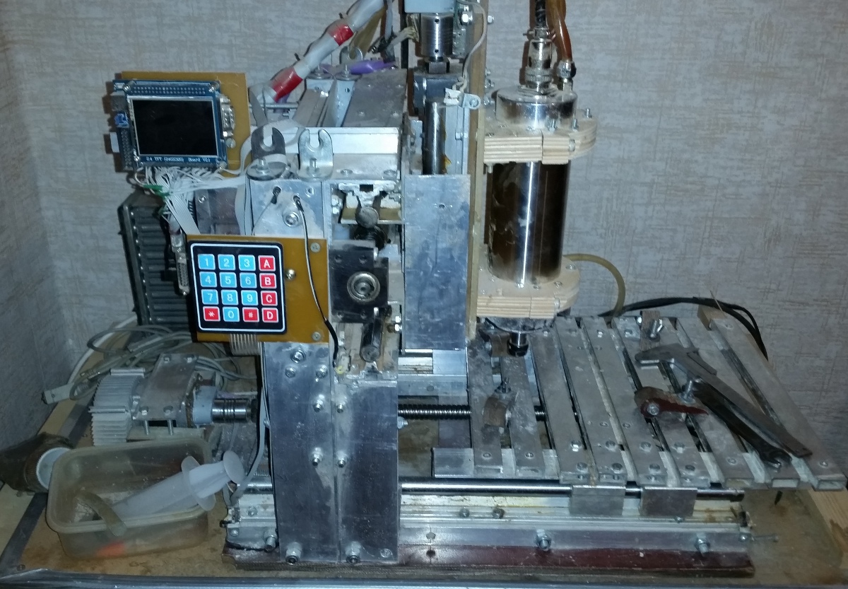
An order for components from China came in a month. And after 2 weeks the machine worked with control from LinuxCNC. I collected from all the garbage that was at hand, because I wanted to quickly (profile + studs). I was going to redo it later, but, as it turned out, the machine turned out to be quite rigid, and I did not have to tighten the nuts on the studs even once. So the design remained unchanged.
Initial operation of the machine showed that:
After the initial operation, I ordered a water-cooled spindle and decided to make the controller for autonomous operation on the cheapest version of the STM32F103, sold complete with a 320x240 LCD screen.
Why people still stubbornly torment 8-bit ATMega for relatively complex tasks, and even through Arduino is a mystery to me. Probably like difficulties.
The program was created after a thoughtful look at the sources of LinuxCNC and gbrl. However, I didn’t take either of those source codes for calculating the trajectory. I wanted to try to write a calculation module without using float. Exclusively on 32-bit arithmetic.
The result suits me for all operating modes and has not touched the firmware for a long time.
Maximum speed, selected experimentally: X: 2000mm / min Y: 1600 Z: 700 (1600 step / mm. Mode 1/8).
But it is not limited by controller resources. Just above the already nasty sound of skipping steps, even straight sections through the air. Budget Chinese step control board on TB6560 is not the best option.
In fact, the wood speed (beech, 5mm deepening, d = 1mm milling cutter, 0.15mm pitch) is not more than 1200 mm. The likelihood of a milling cutter increases.
The result is a controller with the following functionality:
The controller will connect to the step control board through the same LPT connector. Those. it acts as a control computer with LinuxCNC / Mach3 and is interchangeable with it.
After creative experiments on cutting out hand-drawn reliefs on a tree, and experiments with acceleration settings in the program, I also wanted additional encoders on the axes. Just on e-bay I found relatively cheap optical eco-coders (1/512), the division step of which for my ballscrews was 5/512 = 0.0098mm.
By the way, the use of high-resolution optical encoders without a hardware circuit for working with them (in STM32 it is) is pointless. Neither interrupt processing, nor, moreover, program polling, will ever cope with the “bounce” (I say this for ATMega fans).
First of all, I wanted for the following tasks:
However, he found another application for them, albeit in a rather narrow task.
I noticed that when cutting the relief, when setting the acceleration along Z is greater than a certain value, the Z axis begins to slowly but surely crawl down. But, the relief cutting time at this acceleration is 20% less. At the end of the relief cutting 17x20 cm in 0.1 mm increments, the cutter can go down 1-2 mm from the calculated path.
The analysis of the situation in dynamics by encoders showed that when lifting the mill, 1-2 steps are sometimes lost.
A simple step correction algorithm using an encoder gives a deviation of not more than 0.03 mm and allows to reduce processing time by 20%. And even 0.1 mm protrusion on the tree is difficult to notice.
An ideal option for hobby purposes was considered a desktop version with a field slightly larger than A4. And still this is enough for me.
It still remains a mystery to me why everyone chooses a design with a movable portal for desktop machines. Its only advantage is the ability to process a very long board in parts, or if you have to regularly process material whose weight is greater than the weight of the portal.
Over the entire period of operation, there was never a need to cut out in relief the parts on a 3-meter board or to engrave on a stone slab.
The movable table has the following advantages for desktop machines:
I would like to note that this machine is not for power processing. The CNC machine for power processing is easiest to do on the basis of a conventional milling machine.
In my opinion, a machine for power metal processing and a machine with a high revolving spindle for processing wood / plastics are completely different types of equipment.
Create at home a universal machine at least does not make sense.
The choice of spindle for a machine with this type of ballscrew and guides with linear bearings is unambiguous. This is a high revving spindle.
For a typical high-speed spindle (20,000 rpm), milling of non-ferrous metals (there is no question about steel) is an extreme mode for the spindle. Well, perhaps it’s very necessary and then I will eat 0.3 mm per passage with watering the coolant.
A spindle for a machine tool would recommend water-cooled. During operation, only the “singing” of stepper motors and the gurgling of an aquarium pump in the cooling circuit are heard with him.
First of all, the case problem disappeared. The body of any shape is milled from "plexiglass" and glued with solvent on perfectly smooth sections.
Fiberglass refused universal material. The accuracy of the machine allows you to cut out the bearing seat, into which it will go cold, as it should with a slight tightness, and then not pull it out. PCL gears are perfectly cut with an honest involute profile.
Wood processing (reliefs, etc.) is a wide scope for the realization of one’s creative impulses or, at a minimum, for the realization of another’s impulses (ready-made models).
But I haven’t tried jewelry. There is no place to flask / melt / pour flask. Although a bar of jewelry wax is waiting in the wings.
I tried to write only those moments that I personally thought were important.
The link to the controller sources and the configured Eclipse + gcc shell, etc., are in the same place as the movie:
History of creation
Faced regularly with the need to make this or that small “little thing” of complex shape, I initially thought about a 3D printer. And even started to do it. But I read the forums and appreciated the speed of the 3D printer, the quality and accuracy of the result, the percentage of defects and the structural properties of thermoplastics, I realized that this is nothing more than a toy.
An order for components from China came in a month. And after 2 weeks the machine worked with control from LinuxCNC. I collected from all the garbage that was at hand, because I wanted to quickly (profile + studs). I was going to redo it later, but, as it turned out, the machine turned out to be quite rigid, and I did not have to tighten the nuts on the studs even once. So the design remained unchanged.
Initial operation of the machine showed that:
- Using a china noname 220V drill as a spindle is not a good idea. It overheats and works terribly loudly. The side play of the cutter (bearings?) Is felt by the hands.
- The Proxon is quiet. Backlash is not palpable. But it overheats and turns off after 5 minutes.
- A computer taken on time with an LPT bidirectional port is not convenient. Taken on time (finding PCI-LPT turned out to be a problem). Takes a place. And generally speaking..
After the initial operation, I ordered a water-cooled spindle and decided to make the controller for autonomous operation on the cheapest version of the STM32F103, sold complete with a 320x240 LCD screen.
Why people still stubbornly torment 8-bit ATMega for relatively complex tasks, and even through Arduino is a mystery to me. Probably like difficulties.
Controller Development
The program was created after a thoughtful look at the sources of LinuxCNC and gbrl. However, I didn’t take either of those source codes for calculating the trajectory. I wanted to try to write a calculation module without using float. Exclusively on 32-bit arithmetic.
The result suits me for all operating modes and has not touched the firmware for a long time.
Maximum speed, selected experimentally: X: 2000mm / min Y: 1600 Z: 700 (1600 step / mm. Mode 1/8).
But it is not limited by controller resources. Just above the already nasty sound of skipping steps, even straight sections through the air. Budget Chinese step control board on TB6560 is not the best option.
In fact, the wood speed (beech, 5mm deepening, d = 1mm milling cutter, 0.15mm pitch) is not more than 1200 mm. The likelihood of a milling cutter increases.
The result is a controller with the following functionality:
- Connect to an external computer as a standard usb mass storage device (FAT16 on an SD card). Work with files of standard format G-code
- Delete files through the controller user interface.
- Viewing the trajectory of the selected file (as far as the 640x320 screen allows) and calculating the execution time. In fact, emulation of execution with the addition of time.
- View the contents of files in test form.
- Manual control mode from the keyboard (moving and setting "0").
- Start of the task execution on the selected file (G-code).
- Pause / continue execution. (sometimes useful).
- Emergency software stop.
The controller will connect to the step control board through the same LPT connector. Those. it acts as a control computer with LinuxCNC / Mach3 and is interchangeable with it.
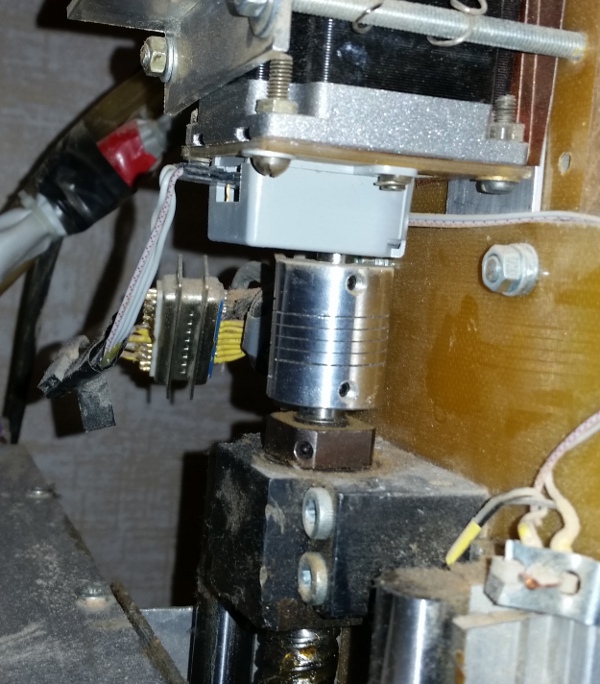
After creative experiments on cutting out hand-drawn reliefs on a tree, and experiments with acceleration settings in the program, I also wanted additional encoders on the axes. Just on e-bay I found relatively cheap optical eco-coders (1/512), the division step of which for my ballscrews was 5/512 = 0.0098mm.
By the way, the use of high-resolution optical encoders without a hardware circuit for working with them (in STM32 it is) is pointless. Neither interrupt processing, nor, moreover, program polling, will ever cope with the “bounce” (I say this for ATMega fans).
First of all, I wanted for the following tasks:
- Manual positioning on the table with high precision.
- Control of skipping steps with control deviation of the trajectory from the calculated.
However, he found another application for them, albeit in a rather narrow task.
Using encoders to correct the path of a machine with stepper motors
I noticed that when cutting the relief, when setting the acceleration along Z is greater than a certain value, the Z axis begins to slowly but surely crawl down. But, the relief cutting time at this acceleration is 20% less. At the end of the relief cutting 17x20 cm in 0.1 mm increments, the cutter can go down 1-2 mm from the calculated path.
The analysis of the situation in dynamics by encoders showed that when lifting the mill, 1-2 steps are sometimes lost.
A simple step correction algorithm using an encoder gives a deviation of not more than 0.03 mm and allows to reduce processing time by 20%. And even 0.1 mm protrusion on the tree is difficult to notice.
Design
An ideal option for hobby purposes was considered a desktop version with a field slightly larger than A4. And still this is enough for me.
Movable table
It still remains a mystery to me why everyone chooses a design with a movable portal for desktop machines. Its only advantage is the ability to process a very long board in parts, or if you have to regularly process material whose weight is greater than the weight of the portal.
Over the entire period of operation, there was never a need to cut out in relief the parts on a 3-meter board or to engrave on a stone slab.
The movable table has the following advantages for desktop machines:
- The structure is simpler and, in general, the structure is more rigid.
- All giblets (power supplies, boards, etc.) are hung on a fixed portal and the machine is more compact and convenient to carry.
- The mass of the table and a piece of typical material for processing is significantly lower than the mass of the portal and spindle.
- The problem with the cables and hoses for water cooling of the spindle practically disappears.
Spindle
I would like to note that this machine is not for power processing. The CNC machine for power processing is easiest to do on the basis of a conventional milling machine.
In my opinion, a machine for power metal processing and a machine with a high revolving spindle for processing wood / plastics are completely different types of equipment.
Create at home a universal machine at least does not make sense.
The choice of spindle for a machine with this type of ballscrew and guides with linear bearings is unambiguous. This is a high revving spindle.
For a typical high-speed spindle (20,000 rpm), milling of non-ferrous metals (there is no question about steel) is an extreme mode for the spindle. Well, perhaps it’s very necessary and then I will eat 0.3 mm per passage with watering the coolant.
A spindle for a machine tool would recommend water-cooled. During operation, only the “singing” of stepper motors and the gurgling of an aquarium pump in the cooling circuit are heard with him.
What can be done on such a machine
First of all, the case problem disappeared. The body of any shape is milled from "plexiglass" and glued with solvent on perfectly smooth sections.
Fiberglass refused universal material. The accuracy of the machine allows you to cut out the bearing seat, into which it will go cold, as it should with a slight tightness, and then not pull it out. PCL gears are perfectly cut with an honest involute profile.
Wood processing (reliefs, etc.) is a wide scope for the realization of one’s creative impulses or, at a minimum, for the realization of another’s impulses (ready-made models).
But I haven’t tried jewelry. There is no place to flask / melt / pour flask. Although a bar of jewelry wax is waiting in the wings.