The second version of the glove for determining the position of the hand
- Tutorial
The previous article was unsuccessful and not informative. Initially, I planned to attach the boards and code for the microcontroller so that anyone could assemble it. But there were so many crutches that it became embarrassing to attach it. Now I will describe the second glove that I collected two weeks ago, and which contains more advanced sensors and provides more accurate data. Although it looks much worse:

1) First of all, these are sensors. Of course, the tilt angles can be determined using accelerometers, but in addition to the noise of the accelerometer, any human movements will also interfere with us. when the hand moves, various accelerations act on it, and not just the acceleration of the free fall of the Earth. Then we decided to take a gyroscope. But the MEMS gyroscope is not at all the gyroscope that we were shown in physics lessons. This gyroscope gives the rate of change of angle. So to get the full angle of deviation from the initial position, we need to integrate these indications. So not only is the signal discrete, there is still the so-called “zero drift”. At rest, the gyroscope does not give out zero, but a very small number other than zero. So, integration will accumulate an error. This is called low frequency gyro noise. What to do? Here the alpha beta filter comes to our aid. It looks like this:

The image is blatantly copied from the bibigone article . The article itself is simply gorgeous. For anyone who wants to deal with sensors, I advise you to read more. And here is a copy of the filter description from the article itself:
Everything is fine, of course, but in the same article in the continuation it is said that we are not going anywhere to drift around the Earth’s acceleration vector. So you need to take one more vector from somewhere, which will not coincide with the acceleration vector. To do this, you need a magnetometer, or as it is also called - a compass.
From all this it follows that we need three sensors: a three-axis accelerometer, a three-axis gyroscope, and a three-axis magnetometer. I don’t want to put three microcircuits on each finger - it will take a lot of space. The need to determine the orientation of various devices in space arises so often that they produce combined sensors. For example, an accelerometer and a gyroscope in one housing, or, as in the case of the MPU-9250, all three sensors in one housing. Due to the fact that they have three three-axis sensors, they are called nine-axis. With these sensors we stocked up.
2) Microcontroller
Although there wasn’t a word about this in the last article, this is still a difference. In the old glove stood my favorite for the price and the STM32F050F4 case. But in the new glove his capabilities were not enough. Neither power nor legs. So it was decided to buy something in the LQFP64 package. This something turned out to be STM32F103. Since the legs were now abundant, it was possible to refuse to use the shift register.
3) Location of sensors. Or rather their number. Now the sensors were installed not only on the fingers, but also on the hand, and on the wrist, and on the forearm. This made it possible to determine the position of the entire arm in space, and not just the fingers.
The differences end there, because there is nothing more to differ. Unless the glove is now on the right hand. The left glove from this pair was used in the previous version:

On the board are divorced: two SPI, two USART, 15GPIO and SWD. At the bottom left, there are three adjacent platforms - a place for the LP2950 stabilizer. Everything else is on a datasheet: power capacitors (tantalum of size D, everything else is 0603, although you can solder 0805 to the same sites if you wish), a capacitor on the Reset leg and capacitors for quartz. The first leg of the microcontroller is the left comb, the upper pin. After sealing all the components and wires from the sensors, everything looks horrible:

I have nothing to justify, except for the word “time”.

Here, as last time, there was a jumper. She is marked by a red line. Unlike the previous glove, there is a small strapping in the face of the capacitor 10 pF from the bottom left and two 0.1 microfarads in other places. The connection scheme is in the datasheet:

I think here any explanations are unnecessary. Solder the case QFN24, solder the jumper and loose, and solder the cable. By the way, the QFN24 case, although it has a smaller step of the legs than the LGA16, but these legs come out from the sides of the microcircuit and you can easily control the quality of the soldering, and in which case you can solder the failed legs with a soldering iron:

Actually got to the programming of all this disgrace. I’ll tell you right away about my mistakes in the previous stages: I personally used the STM32F103RB microcontroller. MK with the prefixes R8 and RB have not only truncated memory, but also truncated peripherals. In particular, there is no USART4, which is in their more "voluminous" brothers. And due to my carelessness, I tried to turn it on for a very long time. After all, he is divorced from me. The fact that USART1 was divorced “just in case” saves us. It remaps to the legs of the PB6 and PB7 microcontroller. Actually, we will do this when we initialize it. But back to the sensor.
The code shown here is also valid for the MPU-6050. This is the same sensor, but without a magnetometer.
First you need to initialize the SPI. To do this, we use this function:
Now you need to initialize the legs of the microcontroller, which are connected to the pins of the CS sensors. We will set up defines for all sensors and write some functions that will simplify our life (for now, don’t pay attention that I have only 6 sensors):
It looks a bit clumsy. It works like this: to select sensor number n, I call the HeSelectSensor (n) function. After that, a logical 0 will be set on the leg for which the sensor is fixed in defines, which means the start of work with the sensor.
We also write functions for communicating with sensors:
Now you can try to check the operability of the sensors. To do this, we will poll the register WHO_AM_I and see the answer. If all is well, then the value of this register will coincide with the default value from the datasheet:

After this ping, I found out that two sensors do not work for me. There was 4 hours left before the plane, all the equipment was already packed in a suitcase, so I decided to put it on two sensors, because they were located on the fingers, and not on the wrist or hand. Fuh. Now it seems that all preparations have ended and you can begin to initialize the sensor. First I wrote my initialization, and then in the process of working on the glove I found a libraryin which everything was well written and with comments. But all the code was for the F401-Nucleo board and the SPI interface. I had to rewrite a lot. And the result of rewriting the initialization looks like this:
We would like to thank the author of the library for the initialization that worked the first time. In general, the library is wonderful, but for I2C and for fans of the mbed library.
Now that the sensors are initialized, we can move on to receiving data.
First you need to teach the controller to communicate with the computer. And then there will be nowhere to transfer our data. To do this, initialize USART1. At the same time, do not forget about the remap of the legs.
We will use the HeSendToUsart function to send data.
Now you can write the main function and interrupts:
This is where the tail feint occurs. First, we initialize everything. This is as usual. And then for some reason we turn on the timer. What for? And with it, we will add gyro readings at regular intervals. The timer is set to 100 interrupts per second. So the sampling rate of the sensors will be 100 sps. Then there is an endless cycle in which a delay is made, after which an array with sensor data is sent. The array looks like xyz of the first sensor, xyz of the second sensor, etc. A total of 18 values (3 axes per 6 sensors).
In the interruption, we first read the readings of the accelerometer and gyroscope, and then substitute the alpha-beta filter. There are two magic numbers. 0.00762939 is the resolution of the gyroscope. Those. using this coefficient, we translate the number received from the gyroscope into an angle. The second magic number is 0.01. This is the actual time between measurements in seconds. It is for this that the timer is used - so that we always know exactly the elapsed time between measurements. The incomprehensible variable r is the alpha-beta filter coefficient multiplied by 100. It was declared at the very beginning of the program and is equal to 10.
Phew Well, that’s all! You can receive data. True, these data are not entirely simple. Since we are sending an eight-bit number in USART, we had to dodge with an angle: the number of 360/256 shares is sent. That is, a tilt angle of 90 degrees corresponds to a value of 63.
Cheers cheers. And so I killed a week and one night. Here are the project sources for the CooCox environment:
Project
If someone has worked with these sensors and has a working code for working with the magnetometer via SPI, then I will be very grateful for his help. I hope this article turned out to be more interesting and useful than the previous one.
PS I forgot to write about my biggest get along! My magnetometer did not work (therefore, I ask you to share the working code.
Differences from the previous version
1) First of all, these are sensors. Of course, the tilt angles can be determined using accelerometers, but in addition to the noise of the accelerometer, any human movements will also interfere with us. when the hand moves, various accelerations act on it, and not just the acceleration of the free fall of the Earth. Then we decided to take a gyroscope. But the MEMS gyroscope is not at all the gyroscope that we were shown in physics lessons. This gyroscope gives the rate of change of angle. So to get the full angle of deviation from the initial position, we need to integrate these indications. So not only is the signal discrete, there is still the so-called “zero drift”. At rest, the gyroscope does not give out zero, but a very small number other than zero. So, integration will accumulate an error. This is called low frequency gyro noise. What to do? Here the alpha beta filter comes to our aid. It looks like this:
The image is blatantly copied from the bibigone article . The article itself is simply gorgeous. For anyone who wants to deal with sensors, I advise you to read more. And here is a copy of the filter description from the article itself:
There is a much simpler filter, which is called just “alpha-beta”, which is, let’s say, okay, let's continue to integrate, just with a little correction, add the angle that we get from the accelerometer. Well, the delta here is some small number, the only parameter of this filter that needs to be selected. Why is it such an alpha beta, sometimes it is also called some kind of “composite filter”. Because this coefficient, it is large enough, it kills low frequencies, and this coefficient is small, it kills high-frequency noise. It turns out that you kill the low frequency of the noise from integration, and here you kill the high frequency, the very noise that comes from the sensor itself.
Everything is fine, of course, but in the same article in the continuation it is said that we are not going anywhere to drift around the Earth’s acceleration vector. So you need to take one more vector from somewhere, which will not coincide with the acceleration vector. To do this, you need a magnetometer, or as it is also called - a compass.
From all this it follows that we need three sensors: a three-axis accelerometer, a three-axis gyroscope, and a three-axis magnetometer. I don’t want to put three microcircuits on each finger - it will take a lot of space. The need to determine the orientation of various devices in space arises so often that they produce combined sensors. For example, an accelerometer and a gyroscope in one housing, or, as in the case of the MPU-9250, all three sensors in one housing. Due to the fact that they have three three-axis sensors, they are called nine-axis. With these sensors we stocked up.
2) Microcontroller
Although there wasn’t a word about this in the last article, this is still a difference. In the old glove stood my favorite for the price and the STM32F050F4 case. But in the new glove his capabilities were not enough. Neither power nor legs. So it was decided to buy something in the LQFP64 package. This something turned out to be STM32F103. Since the legs were now abundant, it was possible to refuse to use the shift register.
3) Location of sensors. Or rather their number. Now the sensors were installed not only on the fingers, but also on the hand, and on the wrist, and on the forearm. This made it possible to determine the position of the entire arm in space, and not just the fingers.
The differences end there, because there is nothing more to differ. Unless the glove is now on the right hand. The left glove from this pair was used in the previous version:
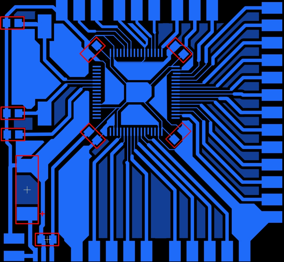
Microcontroller board
On the board are divorced: two SPI, two USART, 15GPIO and SWD. At the bottom left, there are three adjacent platforms - a place for the LP2950 stabilizer. Everything else is on a datasheet: power capacitors (tantalum of size D, everything else is 0603, although you can solder 0805 to the same sites if you wish), a capacitor on the Reset leg and capacitors for quartz. The first leg of the microcontroller is the left comb, the upper pin. After sealing all the components and wires from the sensors, everything looks horrible:
I have nothing to justify, except for the word “time”.
Sensor Board
Here, as last time, there was a jumper. She is marked by a red line. Unlike the previous glove, there is a small strapping in the face of the capacitor 10 pF from the bottom left and two 0.1 microfarads in other places. The connection scheme is in the datasheet:
I think here any explanations are unnecessary. Solder the case QFN24, solder the jumper and loose, and solder the cable. By the way, the QFN24 case, although it has a smaller step of the legs than the LGA16, but these legs come out from the sides of the microcircuit and you can easily control the quality of the soldering, and in which case you can solder the failed legs with a soldering iron:
Sensor Initialization
Actually got to the programming of all this disgrace. I’ll tell you right away about my mistakes in the previous stages: I personally used the STM32F103RB microcontroller. MK with the prefixes R8 and RB have not only truncated memory, but also truncated peripherals. In particular, there is no USART4, which is in their more "voluminous" brothers. And due to my carelessness, I tried to turn it on for a very long time. After all, he is divorced from me. The fact that USART1 was divorced “just in case” saves us. It remaps to the legs of the PB6 and PB7 microcontroller. Actually, we will do this when we initialize it. But back to the sensor.
The code shown here is also valid for the MPU-6050. This is the same sensor, but without a magnetometer.
First you need to initialize the SPI. To do this, we use this function:
SPI Initialization
void HeInitSpi(void)
{
	RCC_APB2PeriphClockCmd(RCC_APB2Periph_GPIOA|RCC_APB2Periph_AFIO, ENABLE); //Включаем тактирование порта А и альтернативной функции GPIO
	RCC_APB2PeriphClockCmd(RCC_APB2Periph_SPI1, ENABLE); //Включаем тактирование SPI
	GPIO_InitTypeDef SpiPort;
	SPI_InitTypeDef SPI_InitStructure;
	SpiPort.GPIO_Mode = GPIO_Mode_AF_PP; //Альтернативная функция Push-Pull
	SpiPort.GPIO_Speed = GPIO_Speed_10MHz; //Максимальная частота переключения 10MHz
	SpiPort.GPIO_Pin = GPIO_Pin_5 | GPIO_Pin_7 | GPIO_Pin_4; //Настраиваемые ноги - 5,6,7
	GPIO_Init(GPIOA, &SpiPort); //Инициализировать порт А.
	SpiPort.GPIO_Mode = GPIO_Mode_IPU; //Вход с подтяжкой к плюсу
	SpiPort.GPIO_Pin = GPIO_Pin_6; //Настраиваемая нога - 6
	GPIO_Init(GPIOA, &SpiPort); //Инициализировать порт А
	SPI_InitStructure.SPI_Direction = SPI_Direction_2Lines_FullDuplex; //Двунаправленный обмен данными
	SPI_InitStructure.SPI_DataSize = SPI_DataSize_8b; //Длинна пакета 8 бит
	SPI_InitStructure.SPI_CPOL = SPI_CPOL_Low; //Активный уровень - низкий
	SPI_InitStructure.SPI_CPHA = SPI_CPHA_1Edge; //Выравнивание по переднему фронту
	SPI_InitStructure.SPI_NSS = SPI_NSS_Soft; //Софтварное управление NSS
	SPI_InitStructure.SPI_BaudRatePrescaler = SPI_BaudRatePrescaler_16; //Предделитель частоты тактирования SPI
	SPI_InitStructure.SPI_FirstBit = SPI_FirstBit_MSB;
	SPI_InitStructure.SPI_Mode = SPI_Mode_Master; //Мы - мастер
	SPI_Init(SPI1, &SPI_InitStructure); //Инициализация SPI
	SPI_Cmd(SPI1, ENABLE); //Включение SPI
	SPI_NSSInternalSoftwareConfig(SPI1, SPI_NSSInternalSoft_Set);
}
Now you need to initialize the legs of the microcontroller, which are connected to the pins of the CS sensors. We will set up defines for all sensors and write some functions that will simplify our life (for now, don’t pay attention that I have only 6 sensors):
Sensor Code
#define SENSOR_0_PORT GPIOA
#define SENSOR_1_PORT GPIOA
#define SENSOR_2_PORT GPIOA
#define SENSOR_3_PORT GPIOC
#define SENSOR_4_PORT GPIOC
#define SENSOR_5_PORT GPIOC
#define SENSOR_0_PIN GPIO_Pin_11
#define SENSOR_1_PIN GPIO_Pin_9
#define SENSOR_2_PIN GPIO_Pin_8
#define SENSOR_3_PIN GPIO_Pin_9
#define SENSOR_4_PIN GPIO_Pin_8
#define SENSOR_5_PIN GPIO_Pin_7
void HeInitSensorsPort(void)
{
	RCC_APB2PeriphClockCmd(RCC_APB2Periph_GPIOA|RCC_APB2Periph_GPIOC|RCC_APB2Periph_AFIO, ENABLE);
	GPIO_InitTypeDef SensorsGpioPin;
	SensorsGpioPin.GPIO_Mode = GPIO_Mode_Out_PP;
	SensorsGpioPin.GPIO_Speed = GPIO_Speed_10MHz;
	SensorsGpioPin.GPIO_Pin = SENSOR_0_PIN|SENSOR_1_PIN|SENSOR_2_PIN;
	GPIO_Init(SENSOR_0_PORT, &SensorsGpioPin);
	SensorsGpioPin.GPIO_Pin = SENSOR_3_PIN|SENSOR_4_PIN|SENSOR_5_PIN;
	GPIO_Init(SENSOR_5_PORT, &SensorsGpioPin);
}
void HeReselectSensors(void)
{
	GPIO_SetBits(SENSOR_0_PORT, SENSOR_0_PIN);
	GPIO_SetBits(SENSOR_1_PORT, SENSOR_1_PIN);
	GPIO_SetBits(SENSOR_2_PORT, SENSOR_2_PIN);
	GPIO_SetBits(SENSOR_3_PORT, SENSOR_3_PIN);
	GPIO_SetBits(SENSOR_4_PORT, SENSOR_4_PIN);
	GPIO_SetBits(SENSOR_5_PORT, SENSOR_5_PIN);
}
void HeSelectSensor (uint16_t data)
{
	switch (data) {
		case 0: HeReselectSensors(); GPIO_ResetBits(SENSOR_0_PORT, SENSOR_0_PIN); break;
		case 1: HeReselectSensors(); GPIO_ResetBits(SENSOR_1_PORT, SENSOR_1_PIN); break;
		case 2: HeReselectSensors(); GPIO_ResetBits(SENSOR_2_PORT, SENSOR_2_PIN); break;
		case 3: HeReselectSensors(); GPIO_ResetBits(SENSOR_3_PORT, SENSOR_3_PIN); break;
		case 4: HeReselectSensors(); GPIO_ResetBits(SENSOR_4_PORT, SENSOR_4_PIN); break;
		case 5: HeReselectSensors(); GPIO_ResetBits(SENSOR_5_PORT, SENSOR_5_PIN); break;
	}
}
It looks a bit clumsy. It works like this: to select sensor number n, I call the HeSelectSensor (n) function. After that, a logical 0 will be set on the leg for which the sensor is fixed in defines, which means the start of work with the sensor.
We also write functions for communicating with sensors:
Functions for communicating with sensors
uint8_t HeSendToSpi(uint16_t nsensor, uint8_t addres, uint8_t data)
{
	HeSelectSensor(nsensor);
	SPI_I2S_SendData(SPI1, addres);
	while(SPI_I2S_GetFlagStatus(SPI1, SPI_I2S_FLAG_BSY) == SET);
	SPI_I2S_ReceiveData(SPI1);
	SPI_I2S_ReceiveData(SPI1);
	SPI_I2S_SendData(SPI1, data);
	while(SPI_I2S_GetFlagStatus(SPI1, SPI_I2S_FLAG_BSY) == SET);
	HeReselectSensors();
	return SPI_I2S_ReceiveData(SPI1);
}
void writeByte(uint16_t sensor, uint8_t address, uint8_t subAddress, uint8_t data)
{
   /*char data_write[2];
   data_write[0] = subAddress;
   data_write[1] = data;
   i2c.write(address, data_write, 2, 0);*/
	if (address==MPU9250_ADDRESS){
		HeSelectSensor(sensor);
		SPI_I2S_SendData(SPI1, subAddress);
		while(SPI_I2S_GetFlagStatus(SPI1, SPI_I2S_FLAG_BSY) == SET);
		SPI_I2S_ReceiveData(SPI1);
		SPI_I2S_ReceiveData(SPI1);
		SPI_I2S_SendData(SPI1, data);
		while(SPI_I2S_GetFlagStatus(SPI1, SPI_I2S_FLAG_BSY) == SET);
		SPI_I2S_ReceiveData(SPI1);
		HeReselectSensors();
	} else
		if (address==AK8963_ADDRESS){
			HeSelectSensor(sensor);
			writeByte(sensor, MPU9250_ADDRESS, I2C_SLV4_ADDR, I2C_SLV4_ADDR&0b01111111);
			writeByte(sensor, MPU9250_ADDRESS, I2C_SLV4_REG, subAddress);
			writeByte(sensor, MPU9250_ADDRESS, I2C_SLV4_DO, data);
			writeByte(sensor, MPU9250_ADDRESS, I2C_SLV4_CTRL, I2C_SLV4_CTRL|0b10000000);
			int i;
			for (i=0; i<0xFF; i++);
			HeReselectSensors();
		}
}
uint8_t readByte(uint16_t sensor, uint8_t address, uint8_t subAddress)
{
    /*char data[1]; // `data` will store the register data
    char data_write[1];
    data_write[0] = subAddress;
    i2c.write(address, data_write, 1, 1); // no stop
    i2c.read(address, data, 1, 0);
    return data[0];*/
	int d;
	if (address==MPU9250_ADDRESS){
		HeSelectSensor(sensor);
		SPI_I2S_SendData(SPI1, subAddress|0b10000000);
		while(SPI_I2S_GetFlagStatus(SPI1, SPI_I2S_FLAG_BSY) == SET);
		SPI_I2S_ReceiveData(SPI1);
		SPI_I2S_ReceiveData(SPI1);
		SPI_I2S_SendData(SPI1, 0xAA);
		while(SPI_I2S_GetFlagStatus(SPI1, SPI_I2S_FLAG_BSY) == SET);
		d=SPI_I2S_ReceiveData(SPI1);
		HeReselectSensors();
	} else
		if (address==AK8963_ADDRESS){
			HeSelectSensor(sensor);
			writeByte(sensor, MPU9250_ADDRESS, I2C_SLV4_ADDR, AK8963_ADDRESS|0b10000000);
			writeByte(sensor, MPU9250_ADDRESS, I2C_SLV4_REG, subAddress);
			writeByte(sensor, MPU9250_ADDRESS, I2C_SLV4_CTRL, I2C_SLV4_CTRL|0b10000000);
			int i;
			for (i=0; i<0xFF; i++);
			d = readByte(sensor, MPU9250_ADDRESS, I2C_SLV4_DI);
			HeReselectSensors();
		}
	return (d);
}
void readBytes(uint16_t sensor, uint8_t address, uint8_t subAddress, uint8_t count, uint8_t * dest)
{
    /*char data[14];
    char data_write[1];
    data_write[0] = subAddress;
    i2c.write(address, data_write, 1, 1); // no stop
    i2c.read(address, data, count, 0);*/
    int ii;
    uint8_t d;
    if (address==MPU9250_ADDRESS){
    	for(ii = 0; ii < count; ii++) {
    		HeSelectSensor(sensor);
			SPI_I2S_SendData(SPI1, ((subAddress|0b10000000)+ii));
			while(SPI_I2S_GetFlagStatus(SPI1, SPI_I2S_FLAG_BSY) == SET);
			SPI_I2S_ReceiveData(SPI1);
			SPI_I2S_ReceiveData(SPI1);
			SPI_I2S_SendData(SPI1, 0xAA);
			while(SPI_I2S_GetFlagStatus(SPI1, SPI_I2S_FLAG_BSY) == SET);
			d=SPI_I2S_ReceiveData(SPI1);
			dest[ii] = d;
			HeReselectSensors();
    	}
    } else
    	for(ii = 0; ii < count; ii++) {
    		if (address==AK8963_ADDRESS){
				HeSelectSensor(sensor);
				writeByte(sensor, MPU9250_ADDRESS, I2C_SLV4_ADDR, I2C_SLV4_ADDR|0b10000000);
				writeByte(sensor, MPU9250_ADDRESS, I2C_SLV4_REG, subAddress+ii);
				writeByte(sensor, MPU9250_ADDRESS, I2C_SLV4_CTRL, I2C_SLV4_CTRL|0b10000000);
				int i;
				for (i=0; i<0xFF; i++);
				d = readByte(sensor, MPU9250_ADDRESS, I2C_SLV4_DI);
				dest[ii] = d;
				HeReselectSensors();
			}
		}
}
Now you can try to check the operability of the sensors. To do this, we will poll the register WHO_AM_I and see the answer. If all is well, then the value of this register will coincide with the default value from the datasheet:
After this ping, I found out that two sensors do not work for me. There was 4 hours left before the plane, all the equipment was already packed in a suitcase, so I decided to put it on two sensors, because they were located on the fingers, and not on the wrist or hand. Fuh. Now it seems that all preparations have ended and you can begin to initialize the sensor. First I wrote my initialization, and then in the process of working on the glove I found a libraryin which everything was well written and with comments. But all the code was for the F401-Nucleo board and the SPI interface. I had to rewrite a lot. And the result of rewriting the initialization looks like this:
Sensor Initialization
void initMPU9250(uint16_t sensor)
{
 // Initialize MPU9250 device
 // wake up device
  writeByte(sensor, MPU9250_ADDRESS, PWR_MGMT_1, 0x00); // Clear sleep mode bit (6), enable all sensors
  int i;
  for (i=0; i<0x3FF; i++); // Delay 100 ms for PLL to get established on x-axis gyro; should check for PLL ready interrupt
  readByte(sensor, MPU9250_ADDRESS, WHO_AM_I_MPU9250);
 // get stable time source
  writeByte(sensor, MPU9250_ADDRESS, PWR_MGMT_1, 0x01);  // Set clock source to be PLL with x-axis gyroscope reference, bits 2:0 = 001
 // Configure Gyro and Accelerometer
 // Disable FSYNC and set accelerometer and gyro bandwidth to 44 and 42 Hz, respectively;
 // DLPF_CFG = bits 2:0 = 010; this sets the sample rate at 1 kHz for both
 // Maximum delay is 4.9 ms which is just over a 200 Hz maximum rate
  writeByte(sensor, MPU9250_ADDRESS, CONFIG, 0x03);
 // Set sample rate = gyroscope output rate/(1 + SMPLRT_DIV)
  writeByte(sensor, MPU9250_ADDRESS, SMPLRT_DIV, 0x04);  // Use a 200 Hz rate; the same rate set in CONFIG above
 // Set gyroscope full scale range
 // Range selects FS_SEL and AFS_SEL are 0 - 3, so 2-bit values are left-shifted into positions 4:3
  uint8_t c =  readByte(sensor, MPU9250_ADDRESS, GYRO_CONFIG);
  writeByte(sensor, MPU9250_ADDRESS, GYRO_CONFIG, c & ~0xE0); // Clear self-test bits [7:5]
  writeByte(sensor, MPU9250_ADDRESS, GYRO_CONFIG, c & ~0x18); // Clear AFS bits [4:3]
  writeByte(sensor, MPU9250_ADDRESS, GYRO_CONFIG, c | Gscale << 3); // Set full scale range for the gyro
 // Set accelerometer configuration
  c =  readByte(sensor, MPU9250_ADDRESS, ACCEL_CONFIG);
  writeByte(sensor, MPU9250_ADDRESS, ACCEL_CONFIG, c & ~0xE0); // Clear self-test bits [7:5]
  writeByte(sensor, MPU9250_ADDRESS, ACCEL_CONFIG, c & ~0x18); // Clear AFS bits [4:3]
  writeByte(sensor, MPU9250_ADDRESS, ACCEL_CONFIG, c | Ascale << 3); // Set full scale range for the accelerometer
 // Set accelerometer sample rate configuration
 // It is possible to get a 4 kHz sample rate from the accelerometer by choosing 1 for
 // accel_fchoice_b bit [3]; in this case the bandwidth is 1.13 kHz
  c = readByte(sensor, MPU9250_ADDRESS, ACCEL_CONFIG2);
  writeByte(sensor, MPU9250_ADDRESS, ACCEL_CONFIG2, c & ~0x0F); // Clear accel_fchoice_b (bit 3) and A_DLPFG (bits [2:0])
  writeByte(sensor, MPU9250_ADDRESS, ACCEL_CONFIG2, c | 0x03); // Set accelerometer rate to 1 kHz and bandwidth to 41 Hz
 // The accelerometer, gyro, and thermometer are set to 1 kHz sample rates,
 // but all these rates are further reduced by a factor of 5 to 200 Hz because of the SMPLRT_DIV setting
  // Configure Interrupts and Bypass Enable
  // Set interrupt pin active high, push-pull, and clear on read of INT_STATUS, enable I2C_BYPASS_EN so additional chips
  // can join the I2C bus and all can be controlled by the Arduino as master
   writeByte(sensor, MPU9250_ADDRESS, INT_PIN_CFG, 0x22);
   writeByte(sensor, MPU9250_ADDRESS, INT_ENABLE, 0x01);  // Enable data ready (bit 0) interrupt
   writeByte(sensor, MPU9250_ADDRESS, I2C_SLV4_ADDR, AK8963_ADDRESS); // Address of mag on I2C bus
   writeByte(sensor, MPU9250_ADDRESS, I2C_MST_CTRL, I2C_MST_CTRL|0x0D); // Speed of I2C 400kHz
}
We would like to thank the author of the library for the initialization that worked the first time. In general, the library is wonderful, but for I2C and for fans of the mbed library.
Now that the sensors are initialized, we can move on to receiving data.
Receiving and processing data
First you need to teach the controller to communicate with the computer. And then there will be nowhere to transfer our data. To do this, initialize USART1. At the same time, do not forget about the remap of the legs.
USART initialization
void HeInitUsartGpio(void)
{
	GPIO_InitTypeDef UsartGPIO;
	RCC_APB2PeriphClockCmd(RCC_APB2Periph_GPIOB|RCC_APB2Periph_AFIO, ENABLE);
	UsartGPIO.GPIO_Mode = GPIO_Mode_AF_PP;
	UsartGPIO.GPIO_Speed = GPIO_Speed_10MHz;
	UsartGPIO.GPIO_Pin = GPIO_Pin_6;
	GPIO_Init(GPIOB, &UsartGPIO);
	UsartGPIO.GPIO_Mode = GPIO_Mode_IN_FLOATING;
	UsartGPIO.GPIO_Pin = GPIO_Pin_7;
	GPIO_Init(GPIOB, &UsartGPIO);
	GPIO_PinRemapConfig(GPIO_Remap_USART1, ENABLE);
}
void HeInitUsart(void)
{
	HeInitUsartGpio();
	USART_InitTypeDef USART1_InitStructure;
	RCC_APB2PeriphClockCmd(RCC_APB2Periph_USART1, ENABLE);
	USART1_InitStructure.USART_BaudRate = 115200;
	USART1_InitStructure.USART_HardwareFlowControl = USART_HardwareFlowControl_None;
	USART1_InitStructure.USART_Mode = USART_Mode_Rx|USART_Mode_Tx;
	USART1_InitStructure.USART_Parity = USART_Parity_No;
	USART1_InitStructure.USART_StopBits = USART_StopBits_1;
	USART1_InitStructure.USART_WordLength = USART_WordLength_8b;
	USART_Init(USART1, &USART1_InitStructure);
	USART_Cmd(USART1, ENABLE);
}
void HeSendToUsart (uint8_t data)
{
	USART_SendData(USART1, data);
	while(!(USART_GetFlagStatus(USART1, USART_FLAG_TC)));
	USART_ClearFlag(USART1, USART_FLAG_TC);
}
We will use the HeSendToUsart function to send data.
Now you can write the main function and interrupts:
main and Ko
int main(void)
{
	HeInitUsart();
	HeInitSensorsPort();
	HeInitSpi();
	initMPU9250(0);
	RCC_APB1PeriphClockCmd(RCC_APB1Periph_TIM4,ENABLE);
	TIM4->PSC = 7200 - 1;
	TIM4->ARR = 100 ;
	TIM4->DIER |= TIM_DIER_UIE;
	TIM4->CR1 |= TIM_CR1_CEN;
	NVIC_InitTypeDef TIMQ;
	TIMQ.NVIC_IRQChannel = TIM4_IRQn;
	TIMQ.NVIC_IRQChannelCmd = ENABLE;
	NVIC_Init(&TIMQ);
	int j;
    while(1){
    	int p;
    	for (p=0; p<18; p++)
    	{
    		HeSendToUsart(SensBuf[p]);
    		HeDelay(0xFF);
    	}
    	HeDelay(0x2FFFF);
    }
    return 0;
}
void TIM4_IRQHandler(void)
{
	TIM4->SR &= ~TIM_SR_UIF;
	int ax, ay, az, gx, gy, gz;
	int j;
	for (j=0; j<6; j++){
		readAccelData(5-j, accelCount);
		readGyroData(5-j, gyroCount);
		ax = accelCount[0];
		ay = accelCount[1];
		az = accelCount[2];
		gx = gyroCount[0];
		gy = gyroCount[1];
		gz = gyroCount[2];
		hy[5-j] =((1 - (r/100)) * (hy[5-j] + (gy*0.00762939) * 0.01)) + ((r/100) * (90+(180/3.1415)*atan2(-az,-ax)));
		hx[5-j] =((1 - (r/100)) * (hx[5-j] + (gx*0.00762939) * 0.01)) + ((r/100) * (180/3.1415)*atan2(ay,az));
		hz[5-j] =((1 - (r/100)) * (hz[5-j] + (gz*0.00762939) * 0.01)) + ((r/100) * (90+(180/3.1415)*atan2(-ay, ax)));
		SensBuf[0+j*3] = ((uint8_t)(int)(hx[5-j]*255/360));
		SensBuf[1+j*3] = ((uint8_t)(int)(hy[5-j]*255/360));
		SensBuf[2+j*3] = ((uint8_t)(int)(hz[5-j]*255/360));
	}
}
This is where the tail feint occurs. First, we initialize everything. This is as usual. And then for some reason we turn on the timer. What for? And with it, we will add gyro readings at regular intervals. The timer is set to 100 interrupts per second. So the sampling rate of the sensors will be 100 sps. Then there is an endless cycle in which a delay is made, after which an array with sensor data is sent. The array looks like xyz of the first sensor, xyz of the second sensor, etc. A total of 18 values (3 axes per 6 sensors).
In the interruption, we first read the readings of the accelerometer and gyroscope, and then substitute the alpha-beta filter. There are two magic numbers. 0.00762939 is the resolution of the gyroscope. Those. using this coefficient, we translate the number received from the gyroscope into an angle. The second magic number is 0.01. This is the actual time between measurements in seconds. It is for this that the timer is used - so that we always know exactly the elapsed time between measurements. The incomprehensible variable r is the alpha-beta filter coefficient multiplied by 100. It was declared at the very beginning of the program and is equal to 10.
Phew Well, that’s all! You can receive data. True, these data are not entirely simple. Since we are sending an eight-bit number in USART, we had to dodge with an angle: the number of 360/256 shares is sent. That is, a tilt angle of 90 degrees corresponds to a value of 63.
That's all!
Cheers cheers. And so I killed a week and one night. Here are the project sources for the CooCox environment:
Project
If someone has worked with these sensors and has a working code for working with the magnetometer via SPI, then I will be very grateful for his help. I hope this article turned out to be more interesting and useful than the previous one.
PS I forgot to write about my biggest get along! My magnetometer did not work (therefore, I ask you to share the working code.