The effect of cables on the parameters of the amplifier-speaker and microphone-mixer systems
The overwhelming majority of audiophiles are confident in the significant influence of cables on sound. A lot of articles have been written on this subject, both supporters and opponents of this theory, however, I have not seen a single article containing real technical calculations that would prove this or that point of view. The texts usually cite their own speculations, which are sometimes far from reality. I used technical knowledge and calculations to understand this topic.
Most often, in addition to the active resistance of the conductor, audiophiles mention three factors that supposedly affect the final parameters of the electrical circuit:
Consider the first two factors in the aggregate, since they have a very close relationship.
The fact is that there is an equivalent circuit of an infinitely small segment of a long power line, which is a four-terminal device containing linear resistance, capacitance, inductance and conductivity (Figure 1). Thus, any long line is a collection of four-terminal data connected in series.
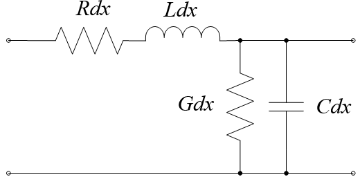
Figure 1 - Equivalent diagram of an infinitely small segment of a long line
However, it should be borne in mind that we are talking about a long line. By definition, a long line is a regular power line, the length of which is many times greater than the wavelength of the vibrations propagating in it, and the distance between the conductors and the transverse size of the conductors are many times smaller than the wavelength, i.e. the relations are satisfied
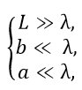
where λ is the wavelength, L is the line length, a is the cross section of the conductor, b is the distance between the conductors. For the upper cutoff frequency ν = 20,000 Hz of the audible range, the wavelength λ = c⁄ν , where c – скорость света, будет равна 300000000/20000=15000 м, или 15 км. Для частоты в 50 Гц длина волны будет достигать шести тысяч километров. Естественно, такие длины акустических кабелей не используются, и поэтому модель длинной линии для них явно не подходит.
Для линий, длина которых много меньше или соизмерима с длиной волны колебаний, существует эквивалентная схема короткой линии (Рисунок 2).
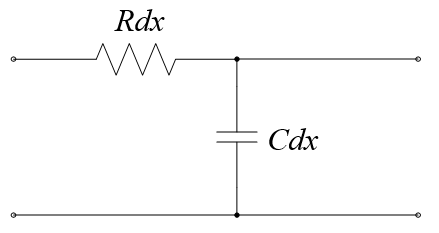
Рисунок 2 – Эквивалентная схема бесконечно маленького отрезка короткой линии
Как видно из рисунка, здесь уже не учитываются проводимость и индуктивность линии, поскольку их значения пренебрежимо малы (для короткой линии). Значит, второй фактор рассматривать смысла нет. Остаётся только ёмкость.
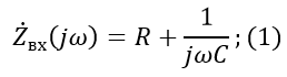
We now calculate the input and output impedances of our passive four-port network and see its transfer characteristic.
The input resistance for the first circuit will be:
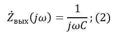
The output resistance for the second circuit:
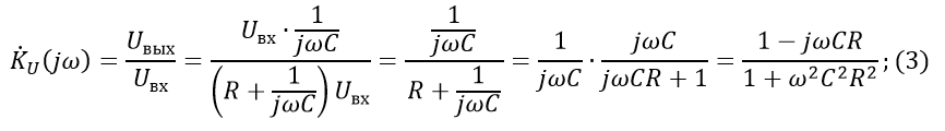
Voltage transfer characteristic : Transfer characteristic
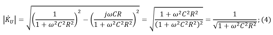
module:
Now, let's take one meter of some real cable for calculation. I went to audiomania.ru and found a cheap Onetech Rapid Two INT0107 microphone cable. One conductor of such a cable has a cross section of 0.21 square mm, which roughly corresponds to the caliber AWG 24, according to the American standard. From the book Fundamentals of Telecommunications, we use a table in which the linear resistance and capacitance are indicated (Figure 3).
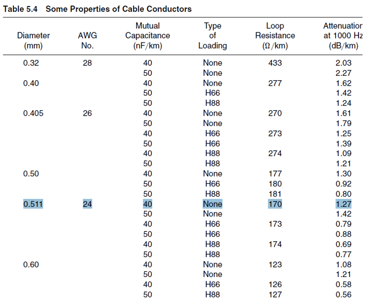
Figure 3 - Cable parameter table (for 1 kHz)
For AWG 24 C = 40 nF⁄km = 40 pF⁄m; R = 170 Ohm⁄km = 0.17 Ohm⁄m, ν = 1000 Hz. We substitute these values into formula (4):

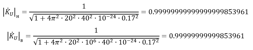
I deliberately left more than 15 decimal places to show how tiny the change in voltage is when passing through a four-terminal network. By the way, it’s difficult to even find a device that will show such accuracy.
Now let's see the boundary value of the frequency spectrum perceived by the human ear ( ν_н = 20 Hz, ν_в = 20,000 Hz):
Skeptics will say: "This is a calculation for just one meter of cable." Well, let's see what happens with the voltage transfer characteristic module for, say, five meters of cable (for 1 kHz).

Changes for five meters of cable are also negligible to take into account.
By definition, a skin effect (or surface effect) is the effect of decreasing the amplitude of electromagnetic waves as they penetrate deeper into the conducting medium. As a result of this effect, for example, an alternating current of high frequency when flowing through a conductor is distributed not uniformly over the cross section, but mainly in the surface layer. It is due to the uneven distribution of current that the effective section of the conductor decreases, and, consequently, the resistance increases.
Such an idea of the skin effect makes audiophiles buy silver-plated wires, which, of course, are much more expensive than ordinary ones (using a thin layer of silver, you can really fight the skin effect for high frequencies, due to the lower resistivity of silver). But does that make sense?
The derivation of the formula describing the skin effect proceeds from the Maxwell equation. It does not make sense to paint it; all the information can be found in textbooks for universities (for example, in the textbook of Sivukhin). Instead of the conclusion, we use a simplified formula for calculating the thickness of the skin layer (a layer in the conductor where almost all the current is concentrated):
where ρ is the resistivity, μ_m is the relative magnetic permeability, and f is the frequency.
For copper: ρ = 0.018 (Ohm ∙ sq. Mm) / m; μ_m = 0.999994 at a frequency f = 20,000 Hz:
We calculate the cross-sectional area in which we have a skin effect:
Thus, for any wire gauge that has a cross-sectional area smaller than 2.95 sq. Mm, the skin effect has no effect whatsoever.
Many lovers of good sound often refer to the damping factor (or damping factor) allegedly described in the German standard DIN 45500 and defining it as the ratio of the load resistance to the output impedance of the amplifier. It is believed that the system falls under the definition of Hi-Fi if its damping coefficient is more than 20. At the same time, the coefficient supposedly takes into account the cable resistance (it is summed with the output impedance of the amplifier), and only its active part. If we use this coefficient, it turns out that the resistance of the conductors not only has a tremendous effect on the speakers, but is almost one of the most important parameters of the speakers. For example, we take the output impedance of the amplifier equal to 0.01 Ohms, then, when you connect the speaker to 4 Ohms with an AWG 24 caliber cable 1 meter long, we get:
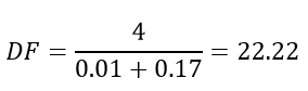
The damping coefficient hardly exceeded 20, and this is only for one meter of cable! What is the matter and to whom to believe?
Honestly, I did not read the DIN 45500 standard, as it is written in German, which I do not speak. However, in Russian national standards there are two analogues to this DIN 45500 for speakers and amplifiers - GOST 23262-88 and GOST 24388-88, respectively. None of them “damping coefficient” is never mentioned, as well as in other state standard specifications, references to which are present in them. This term also does not occur in Russian-language literature. In English-language resources there is information about this parameter, but rather scarce, without references to authoritative sources.
Based on a study conducted at the beginning of the article, I’m almost sure that the “damping coefficient” is nothing more than a myth invented by marketers to increase sales of thick and silver-plated cables worth hundreds or even thousands of dollars. They tried to adjust the coordination of voltages in acoustic systems to a certain parameter, however, the damping coefficient does not characterize the speakers either quantitatively or qualitatively.
Although initially the article considered the effect on the acoustic system, the topic of guitar combos and cables for connecting electric guitars to them surfaced in the comments. It should be noted that this topic requires a slightly different approach to consideration. And that's why.
Any “amplifier-speaker” system or “microphone-mixer” requires matching voltage resistances: the load resistance should be much greater than the source output resistance (in other words, the internal resistance of the signal source). In this case, the voltage that is the carrier of the signal will pass from the source to the load with minimal loss. It is to this type of coordination, first of all, the article relates.
With guitar combos, the story is a little different. Here, due to the features of the electric guitar pickup, power matching is used. In this case, the load resistance should be complexly coupled with the internal resistance of the source (or be close to this state).
With any type of matching for any signal source, the cable is the simplest low-pass filter. The formula for determining the cutoff frequency is as follows:
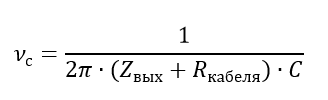
This can be considered an additional limitation that is imposed on the entire system as a whole. In the case of voltage matching, the cutoff frequency will be very high: much more than the upper cutoff frequency of the sound spectrum. The output resistance of an electric guitar can reach hundreds of thousands of ohms (I did not find a more accurate interval in the technical literature), here the cutoff frequency can be within the sound spectrum. Since the internal resistance of the source is very large, the cable resistance for this formula can be neglected, that is, the linear capacity is the most important parameter for such a “guitar” cable. It should be noted that no other phenomena are introduced into the system by cable, that is, the transfer characteristic calculated above is valid up to the cutoff frequency.
I want to note that the capacity of a cable made of copper conductors is determined solely by geometry , that is, the mutual arrangement of the conductors and their linear dimensions (the insulation material, i.e., the dielectric, is not taken into account, since the variation in the dielectric constant of the materials used is relatively small). This means that there are no special technologies for the manufacture of cables that increase the cost to tens of thousands of rubles or more.
From the output of the combo amplifier, the resistance is consistent with the resistance of the remote control by voltage using the DI Box. Connecting an electric guitar without a DI Box will result in severe signal distortion.
The calculations presented in this article clearly show that the effect of cables on the transmission of signals in the frequency spectrum audible to the human ear is negligible for the amplifier-speaker and microphone-mixer systems. There are two types of cables for these systems: working and non-working.
In this case, special attention should be paid to the running capacity for cables connecting electric guitars to combo amplifiers, since the cut-off frequency of the guitar-combic system depends on it.
However, one thing is certain: cables do not introduce any “color”, “mood” and other things that sellers or audiophiles love to talk about.
I dare say that I can in no way affect your freedom of choice - you can buy any cables at any price and for any reason. I wrote all this only as an act of resistance to the spread of technical heresy, which too often began to be introduced by marketers for the sake of making easy money.
List of sources used
1. L.A. Bessonov. Theoretical foundations of electrical engineering. Electrical circuits. - M.: Higher School, 1996 .-- 638 p.
2. D.V. Sivukhin. General physics course. Electricity. T. III - M .: Nauka, 1977 .-- 704 p.
3. A.N. Matveev. Electricity and magnetism. - M.: Higher School, 1983. - 463 p.
4. A.V. Maksimychev. Physical research methods. Lecture notes. Part 2. Signals in long lines. - M.: MIPT, 2003 .-- 43 p.
5. GOST 23262-88. Acoustic household systems. General specifications.
6. GOST 24388-88. Audio signal amplifiers household. General specifications.
7. GOST 16122-87. Loudspeakers Methods for measuring electro-acoustic parameters.
8. Roger L. Freeman. Fundamentals of Telecommunications. - John Wiley & Sons, Inc., 1999. - 676 p.
9. Zernov N.V., Karpov V.G. Theory of radio circuits. - M. - L .: Energy, 1965. - 892 p.
10. Jones M. Kh. Electronics - a practical course. - M .: Technosphere, 2006 .-- 512 p.
Most often, in addition to the active resistance of the conductor, audiophiles mention three factors that supposedly affect the final parameters of the electrical circuit:
- capacitance (since the cable consists of a pair of conductors);
- inductive resistance;
- skin effect.
Consider the first two factors in the aggregate, since they have a very close relationship.
The fact is that there is an equivalent circuit of an infinitely small segment of a long power line, which is a four-terminal device containing linear resistance, capacitance, inductance and conductivity (Figure 1). Thus, any long line is a collection of four-terminal data connected in series.
Figure 1 - Equivalent diagram of an infinitely small segment of a long line
However, it should be borne in mind that we are talking about a long line. By definition, a long line is a regular power line, the length of which is many times greater than the wavelength of the vibrations propagating in it, and the distance between the conductors and the transverse size of the conductors are many times smaller than the wavelength, i.e. the relations are satisfied
where λ is the wavelength, L is the line length, a is the cross section of the conductor, b is the distance between the conductors. For the upper cutoff frequency ν = 20,000 Hz of the audible range, the wavelength λ = c⁄ν , where c – скорость света, будет равна 300000000/20000=15000 м, или 15 км. Для частоты в 50 Гц длина волны будет достигать шести тысяч километров. Естественно, такие длины акустических кабелей не используются, и поэтому модель длинной линии для них явно не подходит.
Для линий, длина которых много меньше или соизмерима с длиной волны колебаний, существует эквивалентная схема короткой линии (Рисунок 2).
Рисунок 2 – Эквивалентная схема бесконечно маленького отрезка короткой линии
Как видно из рисунка, здесь уже не учитываются проводимость и индуктивность линии, поскольку их значения пренебрежимо малы (для короткой линии). Значит, второй фактор рассматривать смысла нет. Остаётся только ёмкость.
We now calculate the input and output impedances of our passive four-port network and see its transfer characteristic.
The input resistance for the first circuit will be:
The output resistance for the second circuit:
Voltage transfer characteristic : Transfer characteristic
module:
Now, let's take one meter of some real cable for calculation. I went to audiomania.ru and found a cheap Onetech Rapid Two INT0107 microphone cable. One conductor of such a cable has a cross section of 0.21 square mm, which roughly corresponds to the caliber AWG 24, according to the American standard. From the book Fundamentals of Telecommunications, we use a table in which the linear resistance and capacitance are indicated (Figure 3).
Figure 3 - Cable parameter table (for 1 kHz)
For AWG 24 C = 40 nF⁄km = 40 pF⁄m; R = 170 Ohm⁄km = 0.17 Ohm⁄m, ν = 1000 Hz. We substitute these values into formula (4):
I deliberately left more than 15 decimal places to show how tiny the change in voltage is when passing through a four-terminal network. By the way, it’s difficult to even find a device that will show such accuracy.
Now let's see the boundary value of the frequency spectrum perceived by the human ear ( ν_н = 20 Hz, ν_в = 20,000 Hz):
Skeptics will say: "This is a calculation for just one meter of cable." Well, let's see what happens with the voltage transfer characteristic module for, say, five meters of cable (for 1 kHz).
Changes for five meters of cable are also negligible to take into account.
About the skin effect
By definition, a skin effect (or surface effect) is the effect of decreasing the amplitude of electromagnetic waves as they penetrate deeper into the conducting medium. As a result of this effect, for example, an alternating current of high frequency when flowing through a conductor is distributed not uniformly over the cross section, but mainly in the surface layer. It is due to the uneven distribution of current that the effective section of the conductor decreases, and, consequently, the resistance increases.
Such an idea of the skin effect makes audiophiles buy silver-plated wires, which, of course, are much more expensive than ordinary ones (using a thin layer of silver, you can really fight the skin effect for high frequencies, due to the lower resistivity of silver). But does that make sense?
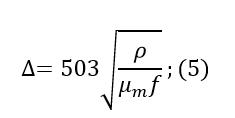
The derivation of the formula describing the skin effect proceeds from the Maxwell equation. It does not make sense to paint it; all the information can be found in textbooks for universities (for example, in the textbook of Sivukhin). Instead of the conclusion, we use a simplified formula for calculating the thickness of the skin layer (a layer in the conductor where almost all the current is concentrated):
where ρ is the resistivity, μ_m is the relative magnetic permeability, and f is the frequency.
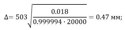
For copper: ρ = 0.018 (Ohm ∙ sq. Mm) / m; μ_m = 0.999994 at a frequency f = 20,000 Hz:
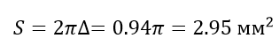
We calculate the cross-sectional area in which we have a skin effect:
Thus, for any wire gauge that has a cross-sectional area smaller than 2.95 sq. Mm, the skin effect has no effect whatsoever.
About damping coefficient
Many lovers of good sound often refer to the damping factor (or damping factor) allegedly described in the German standard DIN 45500 and defining it as the ratio of the load resistance to the output impedance of the amplifier. It is believed that the system falls under the definition of Hi-Fi if its damping coefficient is more than 20. At the same time, the coefficient supposedly takes into account the cable resistance (it is summed with the output impedance of the amplifier), and only its active part. If we use this coefficient, it turns out that the resistance of the conductors not only has a tremendous effect on the speakers, but is almost one of the most important parameters of the speakers. For example, we take the output impedance of the amplifier equal to 0.01 Ohms, then, when you connect the speaker to 4 Ohms with an AWG 24 caliber cable 1 meter long, we get:
The damping coefficient hardly exceeded 20, and this is only for one meter of cable! What is the matter and to whom to believe?
Honestly, I did not read the DIN 45500 standard, as it is written in German, which I do not speak. However, in Russian national standards there are two analogues to this DIN 45500 for speakers and amplifiers - GOST 23262-88 and GOST 24388-88, respectively. None of them “damping coefficient” is never mentioned, as well as in other state standard specifications, references to which are present in them. This term also does not occur in Russian-language literature. In English-language resources there is information about this parameter, but rather scarce, without references to authoritative sources.
Based on a study conducted at the beginning of the article, I’m almost sure that the “damping coefficient” is nothing more than a myth invented by marketers to increase sales of thick and silver-plated cables worth hundreds or even thousands of dollars. They tried to adjust the coordination of voltages in acoustic systems to a certain parameter, however, the damping coefficient does not characterize the speakers either quantitatively or qualitatively.
About coordination of resistances and "guitar" cables
Although initially the article considered the effect on the acoustic system, the topic of guitar combos and cables for connecting electric guitars to them surfaced in the comments. It should be noted that this topic requires a slightly different approach to consideration. And that's why.
Any “amplifier-speaker” system or “microphone-mixer” requires matching voltage resistances: the load resistance should be much greater than the source output resistance (in other words, the internal resistance of the signal source). In this case, the voltage that is the carrier of the signal will pass from the source to the load with minimal loss. It is to this type of coordination, first of all, the article relates.
With guitar combos, the story is a little different. Here, due to the features of the electric guitar pickup, power matching is used. In this case, the load resistance should be complexly coupled with the internal resistance of the source (or be close to this state).
With any type of matching for any signal source, the cable is the simplest low-pass filter. The formula for determining the cutoff frequency is as follows:
This can be considered an additional limitation that is imposed on the entire system as a whole. In the case of voltage matching, the cutoff frequency will be very high: much more than the upper cutoff frequency of the sound spectrum. The output resistance of an electric guitar can reach hundreds of thousands of ohms (I did not find a more accurate interval in the technical literature), here the cutoff frequency can be within the sound spectrum. Since the internal resistance of the source is very large, the cable resistance for this formula can be neglected, that is, the linear capacity is the most important parameter for such a “guitar” cable. It should be noted that no other phenomena are introduced into the system by cable, that is, the transfer characteristic calculated above is valid up to the cutoff frequency.
I want to note that the capacity of a cable made of copper conductors is determined solely by geometry , that is, the mutual arrangement of the conductors and their linear dimensions (the insulation material, i.e., the dielectric, is not taken into account, since the variation in the dielectric constant of the materials used is relatively small). This means that there are no special technologies for the manufacture of cables that increase the cost to tens of thousands of rubles or more.
From the output of the combo amplifier, the resistance is consistent with the resistance of the remote control by voltage using the DI Box. Connecting an electric guitar without a DI Box will result in severe signal distortion.
Conclusion
The calculations presented in this article clearly show that the effect of cables on the transmission of signals in the frequency spectrum audible to the human ear is negligible for the amplifier-speaker and microphone-mixer systems. There are two types of cables for these systems: working and non-working.
In this case, special attention should be paid to the running capacity for cables connecting electric guitars to combo amplifiers, since the cut-off frequency of the guitar-combic system depends on it.
However, one thing is certain: cables do not introduce any “color”, “mood” and other things that sellers or audiophiles love to talk about.
I dare say that I can in no way affect your freedom of choice - you can buy any cables at any price and for any reason. I wrote all this only as an act of resistance to the spread of technical heresy, which too often began to be introduced by marketers for the sake of making easy money.
List of sources used
1. L.A. Bessonov. Theoretical foundations of electrical engineering. Electrical circuits. - M.: Higher School, 1996 .-- 638 p.
2. D.V. Sivukhin. General physics course. Electricity. T. III - M .: Nauka, 1977 .-- 704 p.
3. A.N. Matveev. Electricity and magnetism. - M.: Higher School, 1983. - 463 p.
4. A.V. Maksimychev. Physical research methods. Lecture notes. Part 2. Signals in long lines. - M.: MIPT, 2003 .-- 43 p.
5. GOST 23262-88. Acoustic household systems. General specifications.
6. GOST 24388-88. Audio signal amplifiers household. General specifications.
7. GOST 16122-87. Loudspeakers Methods for measuring electro-acoustic parameters.
8. Roger L. Freeman. Fundamentals of Telecommunications. - John Wiley & Sons, Inc., 1999. - 676 p.
9. Zernov N.V., Karpov V.G. Theory of radio circuits. - M. - L .: Energy, 1965. - 892 p.
10. Jones M. Kh. Electronics - a practical course. - M .: Technosphere, 2006 .-- 512 p.