Tale of the development of an active wireless HiFi speaker system. And about. Part 1
Background
From time to time I practice walking around the electronics stores, audio equipment. It is interesting to see what progress has come to, what new things are being done. Well, not much is being done. I mean a fundamentally new one. Element base is being improved. There are new chips in digital processing. Well, in general, the circuitry has remained the same circuitry. Only now our audio equipment is completely gone. Japan, USA, Korea, China, Italy ... but not Russia.
Why?
He was engaged in monitoring Runet open spaces in order to understand what we generally do from audio. As it turned out, we do a little and mostly expensive. Not in the sense of “not worth the money”, it’s just that this technique is designed for special connoisseurs. There are no high-quality speakers for the ordinary working-peasant class.
Well, the second point. Outside the window is the age of wireless technology. Everything that can be transmitted wirelessly is transmitted wirelessly. To transmit an audio signal (analog) without loss of quality does not seem to me like. And the code is not a problem at all. It will only be necessary to DAC the code in the speaker itself.
Formulation of the problem
You definitely need to do something.
To understand what exactly to do and how - a specific task is needed. If you want - a technical task.
1. The entire analog part is done according to the classics. Well, respectively, unless the modern element base is taken. Well, a little circuitry is sucked;
2. The formation of the audio signal from the code is carried out directly by the speaker itself. Those. concept - sound card inside. This gives full independence of the sound quality at the output of the speaker from what it has at the input. Expensive PC or half dead laptop. Sound depends only on the quality of the DAC (and its implementation) in the speaker.
3. Wireless code transmission. You can create a radio channel with a bandwidth for audio transmission Fs = 44.1 kHz and a bit depth of 16 stereo using the CC8520 chip. It remains to calculate the antenna at 2.4 GHz.
It seems somehow like that.
We do it.
Codename IO
"Io" is the satellite of Jupiter. One of the three. Well, such a goddess in Greek mythology was. Well, now there will be such acoustics.
In general, there is, of course, the idea to make something super small and cheap, and vice versa. Honest three-strip. Let's see how it goes.
After setting the problem and making a decision, a rather lengthy and tedious process of constructing a functional diagram (although no, the functional is quickly done) and selecting electronic components, searching for circuit solutions, drawing circuits, wiring boards, etc., takes place. etc. (but this is really a long time).
Briefly, that during this process I realized for myself.
1. We have practically no integrated circuits. As for DACs, high-quality opamps, power amplifiers, transceivers, then everything is generally sad;
2. But it’s kind of like we know how to make “frizz” - capacitors, coils, transformers, transistors, etc.
3. Well, we also have our own speakers. Joyfully;
4. By organizing the development process - you can never do anything in the time frame that you plan in advance. Any terms need to be doubled.
I’ll give a functional diagram (I will omit all the principle ones, there are quite a few of them, they are large, and I think they will change as well):
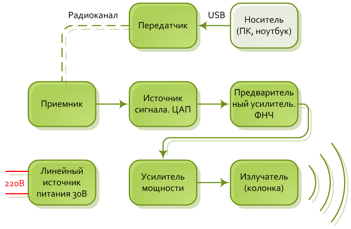
Figure 1. AC principal diagram
A small explanation for each node
Linear power supply. Toroidal transformer type TTP100. Two secondary windings. Gretz diode bridge. Well, plus a capacitor to ground (common point) for each output voltage. Everything is classic. This is the primary source that connects to 220 V. It feeds power amplifiers (for amplifiers a little lower).

Figure 2. Linear power supply
. Also, two step-down stabilizers are included in the source.
The first to power the pre-amplifier is ± 13 V. The stab is also done according to the classical scheme from the textbook on npn and pnp transistors K815G, K814G and Zener diodes KS213B. Below is an approximate circuit of a positive voltage stabilizer 30 V - 13 V. In the negative branch, the circuit is similar, it differs only in the orientation of the zener diode and diode. Well, the transistor with npn is replaced by pnp. The output voltage is regulated by resistors R1 and R2.

Figure 3. 13 V
stabilizer. Second stabilizer +3.3 V. Represents LDO type LT3062 or similar. The output voltage is regulated by a resistive divider. We power the DAC and transceiver. The typical scheme of the "datasheet", I will not give.
Receiver and transmitterdo on the CC8520. The heart of wireless transmission. Without it, the number would have to be driven by USB. This is a high-quality integrated sound transmitter for the 2.4 GHz ISM band.
Texas instruments' PurePath wireless platform is the thing for wireless transmission of high-quality digital audio.
In this case, due to internal signal processing, there is no interference between the audio stream and the WiFi data stream (transmitted on the same carrier frequency).
The transmitter supports 2 audio channels. The CC8520 works autonomously and can be used without or in conjunction with an external MCU. An external processor is connected via the SPI interface and controls some operations.
The CC8520 integrates seamlessly with other audio microchips and DSPs (using I2S and DSP / TDM). You can transmit a signal with a sampling frequency of up to 48 kHz and a resolution of up to 24. This is quite enough to transfer most of the flasks and other lossless ones. Well, audio cd also fits comfortably into these frames.
To represent the scale of disasters of what can be done on the cs8520, I attached the picture below.

Figure 4. Application of CC8520
Transmitter scheme - done in the form of a flash drive. It is installed in the USB of a computer or laptop.

Figure 5. USB transmitter
Below is a diagram of the receiving side. Located in speakers
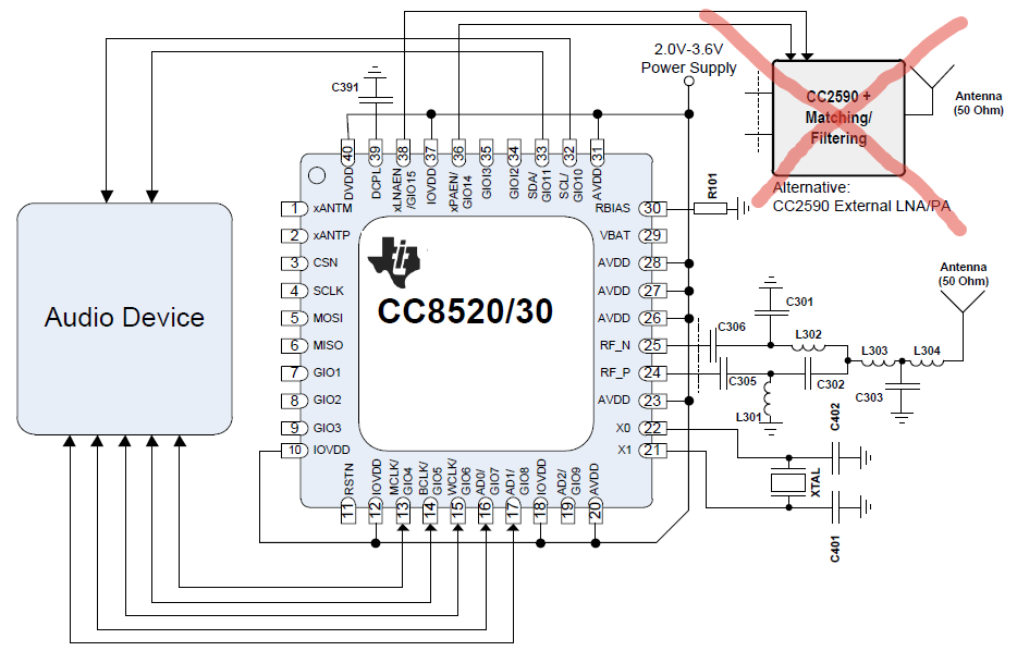
Figure 6. Receiver
A matching circuit / external RF amplifier is not used (crossed out in red on the diagram). Those. the matching circuit with the antenna will certainly be, but not in the form of a separate power chip / amplifier.
DAC WM8940 - Sigma Delta Audio DAC from Wolfson. A fairly common thing, widely used in portable devices and external sound cards Fiio x3, ibasso dx50, irirver astell kern, etc. If you believe the audio forums - DAC is very good. The sound is transparent, analytical, even, even, clear, "adult". At one time, I densely used large audio players based on it. Fiio and iHiFi. It sounds of course very cool. Not soapy. Purely. Clearly. However, recently tired of carrying bricks. He went towards the portable.
The DAC switching circuit is close to standard.
Preamplifier , aka low pass filter. Performed on a two-channel operational amplifier texas burn brown opa2134.
Power Amplifier TDA7293. Also quite an interesting chip. It can deliver up to 40 watts into an 8-ohm load with virtually no distortion (THD <1%). And the theoretical maximum is 100W.
The speakers are two-way. The volume is slightly less than 40 liters. The case is wood.

Figure 7. Speaker appearance
A brief conclusion on the first part
At this stage, almost all electronic components are assembled (who is not assembled is ordered). Almost all printed circuit boards are divorced. And some of them have already been assembled and tested. Now we order the rest.
The next step is tuning, testing, bringing to mind.
Well, in general terms, I think that the very idea of a wireless speaker with a built-in sound card is what the audio multimedia industry and relatively inexpensive high-end will come to sooner or later (although not only they can). IMHO. Everything in this world, in one way or another, is committed to innovation. Wireless technology is what audio technology is lacking at this stage.
There are many unsolved problems at the moment in audio:
1. Creation of small speakers playing the entire audible frequency range. In my opinion, the future in this regard is the pre-emphasis technique and the technique of compensating for the elastic vibrations arising inside the box (if we are talking about speakers). Pre-emphasis is a purely digital theme. Compensation - a review of the box design. Well, in general, it seems to me that in the future evolution should go not along the diffuser path, but a hybrid between electrostatics and iso (or ortho) speakers. Still, from the speakers, almost everything that could be pulled out, in terms of quality, was pulled out. And the film still has potential. And of course, ionophones are also a direction in which little has been done.
2. Well, if now the speaker rules the world, then you need to deal with its fundamental "sores." The inertia of the diffuser and coil. Well, narrowband there too.
3. Getting rid of all signal wires, because in fact, they do not carry any function other than transport. For this, for example, you can make a receiver and a DAC in each column;
4. Wireless power - I don’t even know yet;
5. Transformation of voltage from 220V to lower voltage. Here, I think, the future lies with semiconductor circuitry.
We just decided to combine the three systems into one, and in parallel we are trying to solve one of the above problems.
But it all starts small.