Cards from hexagons in Unity: water, objects of a relief and fortress walls
- Transfer
Parts 1-3: the mesh, colors and heights of the cells
Parts 4-7: bumps, rivers and roads
Parts 8-11: water, objects of the relief and walls of
Parts 12-15: preservation and loading, textures, distances
Parts 16-19: search for the path, player squads, animations
Parts 20-23: fog of war, map exploration, procedural generation
Parts 24-27: water cycle, erosion, biomes, cylindrical map
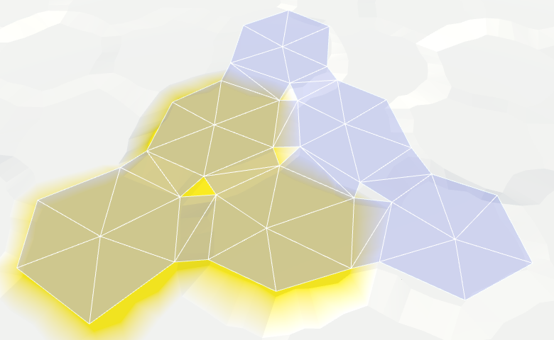
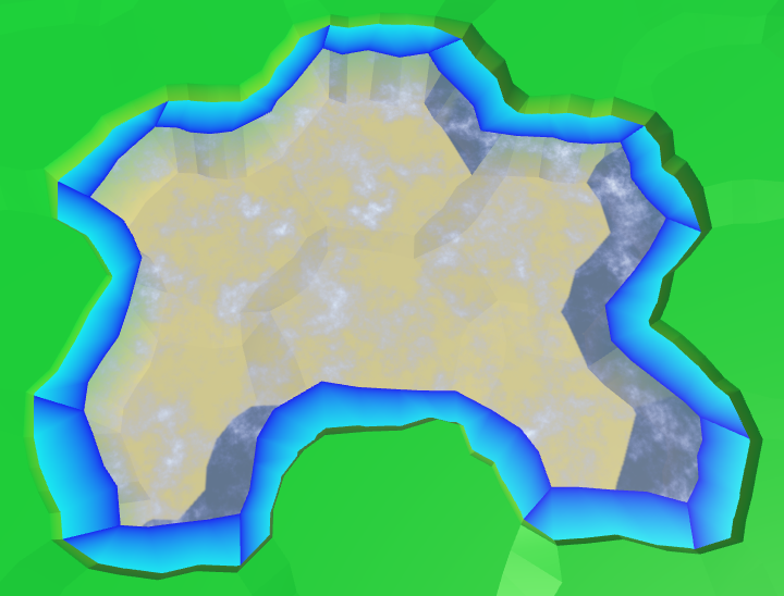
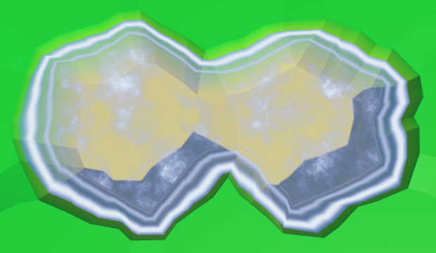
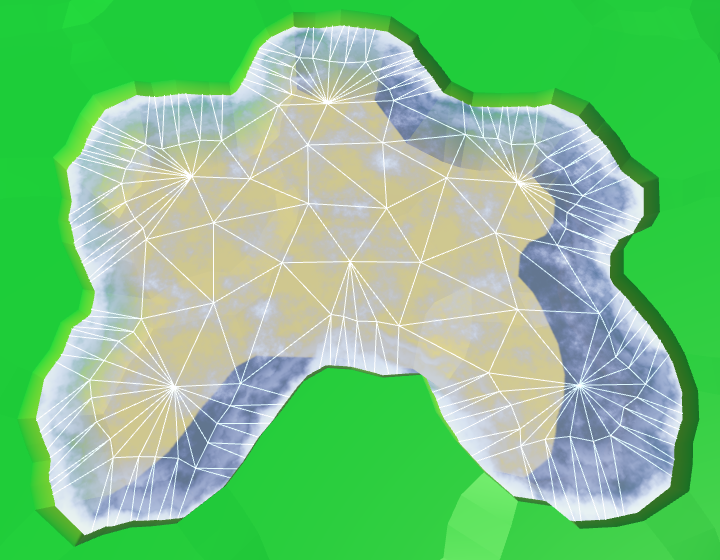
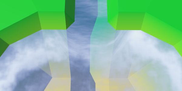
We have already added support for the rivers, and in this part we will completely submerge the cells in water.

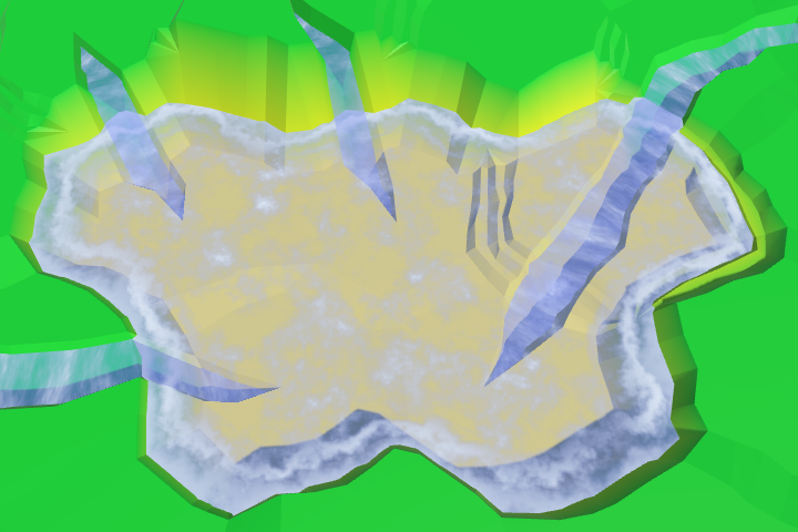
Water is coming.
The easiest way to implement water support is to set it at the same level. All cells below this level are submerged in water. But a more flexible way is to support water at different heights, so let's make the water level changeable. For this you need to
If desired, you can make sure that certain features of the relief do not exist under water. But for now I will not do this. Things like underwater roads suit me. They can be considered areas that have recently been flooded.
Now that we have water levels, the most important question is whether the cells are under water. The cell is under water if its water level is higher than its height. To get this information, we will add a property.
This means that when the water level and height are equal, the cell rises above the water. That is, the real surface of the water is below this height. As is the case with river surfaces, let's add the same offset -
Change it
Editing the water level is similar to changing the height. Therefore, it
Add methods to connect these parameters with the UI.
And add the water level in
To add a water level to the UI, duplicate the label and the height slider, and then change them. Do not forget to attach their events to the appropriate methods.
Water level slider.
unitypackage
To triangulate water, we need a new mesh with new material. First create the Water shader by duplicating the River shader . Change it to use the color property.
Create a new material with this shader by duplicating the Water material and replacing it with a shader. Let's leave the noise texture, because later we use it.

Material Water.
Add a new child to the prefab by duplicating the Rivers child . It does not need UV coordinates, and it must use Water . As usual, let's do this by creating an instance of the prefab, changing it, and then applying the changes to the prefab. After that, get rid of the instance.
Child Water object.
Next, add in the
And connect it with the child object of the prefab.
Water object is connected.
Since water forms the second layer, let's give it its own triangulation method for each of the directions. We only need to call it when the cell is immersed in water.
As in the case of rivers, the height of the water surface does not vary much in cells with the same water level. Therefore, we do not seem to need complex edges. A simple triangle is enough.

Hexagons of water.
We can connect adjacent cells with water with one quadrilateral.
Joining the edges of the water.
And fill the corners with one triangle.
Connection angles of water.
Now we have water cells connected when they are nearby. They leave a gap between themselves and dry cells with greater height, but we will leave that for later.
We assumed that the neighboring submarine cells have the same water level. If it is, then everything looks good, but if this assumption is violated, then errors occur.
Inconsistent water levels.
We can make water stay at the same level. For example, if the water level of a flooded cell changes, we can spread the changes to neighboring cells to keep the levels in sync. However, this process must continue until it encounters cells that are not immersed in water. These cells set the boundaries of the water body.
The danger of this approach is that it can quickly get out of control. If editing is unsuccessful, water can cover the entire map. Then all fragments will have to be triangulated at the same time, which will lead to a huge jump in delays.
So let's not do it yet. This function can be added in a more complex editor. As long as the consistency of water levels, we leave on the conscience of the user.
unitypackage
Instead of a uniform color, we will create something resembling a wave. As in other shaders, we still will not strive for beautiful graphics, we only need to designate the waves.
Perfectly flat water.
Let's do the same thing we did with the rivers. Let's sample the noise with the position of the world and add it to the uniform color. To animate the surface, add time to the V coordinate.
Water scrolling, time × 10.
So far this is not at all like waves. Let's complicate the picture by adding a second sample of noise
and this time adding the U coordinate. Use another noise channel to get two different patterns as a result. The finished waves will be these two samples stacked together.
When summing both samples, we get results in the range of 0–2, so we need to scale it back to 0–1. Instead of simply dividing the waves in half, we can use the function
Two directions, time × 10.
It is still noticeable that we have two moving noise patterns that do not actually change. It would be plausible if the patterns were changed. We can accomplish this by performing interpolation between different channels of noise samples. But this cannot be done in the same way, otherwise the entire surface of the water will change simultaneously, and this is very noticeable. Instead, we will create a wave of mixing.
We will create a mixing wave using a sine wave that moves diagonally across the surface of the water. We will do this by adding the coordinates of the world X and Z and using the sum as the input data for the function
Sinusoids range from -1 and 1, and we need an interval of 0–1. You can get it by squaring the wave. To see the isolated result, use it instead of the changed color as the output value.
Waves of confusion.
To make blending waves less noticeable, let's add a bit of noise from both samples to them.
Distorted mixing waves.
Finally, use a mixing wave to interpolate between the two channels of both noise samples. For maximum variability, take four different channels.
Wave mixing, time × 2.
unitypackage
We ended up with open water, but now we need to fill the gap in the water along the coast. Since we have to comply with the land contours, the water of the coast requires a different approach. Let's divide
There is no triangulation along the coast.
Since the coast is distorted, we must distort the triangles of water along the coast. Therefore, we need vertices of edges and a fan of triangles.
Fan triangles along the coast.
Next comes a strip of ribs, as in the usual relief. However, we are not obliged to limit ourselves only to certain directions, because we
Stripes of ribs along the coast.
Similarly, we must also add an angular triangle each time.
The angles of the ribs along the coast.
Now we have ready water coast. A part of it is always below the relief mesh, so there are no holes.
We can leave everything as it is, but it would be interesting if the coastal water had its own schedule. For example, the effect of foam, which becomes larger when approaching the coast. To implement it, the shader must know how close the fragment is to the coast. We can transmit this information via UV coordinates.
Open water does not have UV coordinates, and does not need foam. It is needed only for water near the coast. Therefore, the requirements for both types of water are quite different. It will be logical to create your own mesh for each type. Therefore, we add
This new mesh will use
Duplicate the water object, connect it with the prefab and configure it so that it uses the UV coordinates. We will also create a shader and material for coastal water, duplicating the existing shader and water material.
Water shore object and material with UV.
Change the Water Shore shader so that instead of water it displays the UV coordinates.
Since the coordinates are not yet specified, it will display a solid color. This makes it easy to see that the coast actually uses a separate mesh with material.
Separate mesh for the coast.
Let's put information about the coast in the coordinate V. On the water side, we assign it a value of 0, on the land side - a value of 1. Since we don’t need to transmit anything more, all U coordinates will simply be 0.
Transitions to the coasts, wrong.
The above code works for edges, but is erroneous in some angles. If the next neighbor is under water, then this approach will be correct. But when the next neighbor is not under water, the third vertex of the triangle will be under dry land.
Transitions to the coasts, correct.
Now that the transitions to the coast have been implemented correctly, you can use them to create a foam effect. The easiest way to add the value of the coast to a uniform color.
Linear foam.
To make the foam more interesting, multiply it by the square of the sine wave.
Fading square sinusoid foam.
Let's make the foam front bigger as we get closer to the shore. This can be done by taking its square root before using the value of the coast.
Foam becomes thicker near the shore.
Add distortion to make it look more natural. Let us make it so that when approaching the shore, the distortion becomes weaker. So it will better fit the coastline.
Distorted foam.
And, of course, all this is animated: both a sine wave and distortion.
Animated foam.
In addition to foam arriving, there is a retreating. Let's add a second sinusoid for its simulation, which moves in the opposite direction. Make it weaker and add a time shift. The finished foam will be the maximum of these two sinusoids.
Inbound and receding foam.
There is a sharp transition between open and coastal waters, because open water waves are not included in the coastal waters. To fix this, we need to include these waves in the Water Shore shader .
Instead of copying the code of the waves, let's paste it into the Water.cginc include file . In fact, we insert code for foam and for waves, each as a separate function.
Change the Water shader to use the new include file.
The Water Shore shader calculates values for both foam and waves. Then we mute the waves as we approach the shore. The finished result will be a maximum of foam and waves.
Mixing foam and waves.
unitypackage
Part of the coastal mesh is hidden under the mesh of the relief. This is normal, but only a small part is hidden. Unfortunately, steep cliffs hide most of the coastal water, and therefore foam.
Almost hidden coastal water.
We can handle this by increasing the size of the coastline. This can be done by reducing the radius of the hexagons of water. For this, in addition to the integrity coefficient, we need
Integrity factor is 0.8. To double the size of the water compounds, we need to assign a value of 0.6 to the water coefficient.
We use these new methods
Using angles of water.
The distance between the hexagons of water has indeed doubled. Now
Let's change it
Long bridges in the water.
Although this gives us more space for the foam, now even more is hidden under the relief. Ideally, we will be able to use the water edge from the water side, and the land edge from the land side.
We cannot use a simple bridge to find the opposite edge of the land, if we start from the corners of the water. Instead, we can go in the opposite direction, from the center of the neighbor. Modify
Wrong corners of edges.
It worked, but now we again need to consider two cases for corner triangles.
The correct angles of the edges.
It worked well, but now that most of the foam is visible, it becomes quite pronounced. To compensate for this, we will make the effect a bit weaker, reducing the scale of the coast in the shader.
Ready foam.
unitypackage
We ended up with water, at least in those places where rivers do not flow into it. Since water and rivers do not notice each other yet, rivers will flow through and under the water.
Rivers flowing in water.
The order in which translucent objects are rendered depends on their distance from the camera. The closest objects are rendered last, so they are at the top. When you move the camera, this will mean that sometimes rivers and sometimes water will appear over each other. Let's start by making the rendering order constant. Rivers must be drawn on top of the water so that waterfalls are displayed correctly. We can accomplish this by changing the River shader's queue .
Draw the river last.
Although the river bed may well be under water, and water can actually flow through it, we should not see this water. And even more so it should not be rendered on top of the real surface of the water. We can get rid of the water of submarine rivers by adding river segments only when the current cell is not under water.
To
No more submarine rivers.
There are no more submarine rivers, but now we have holes in those parts of the rivers where they meet the surface of the water. Rivers flush with water create small holes or overlaps. But the most noticeable are the missing waterfalls for rivers flowing from a greater height. Let's do it first.
The river segment with a waterfall used to pass through the surface of the water. As a result, it was partially over, and partly under water. We need to keep a part above the water level, discarding everything else. We have to work hard for this, so we will create a separate method.
The new method requires four peaks, two levels of rivers and water level. We will set it up so that we look in the direction of the current, down the waterfall. Therefore, the first two vertices and the left and right sides will be on top, followed by the lower ones.
Let's call this method in
We also need to process waterfalls in the opposite direction, when the current cell is under water and the next cell is not.
So we again get the quad of the source river. Next, we need to change
We interpolate.
To move the lower peaks up, divide their distance below the water surface by the height of the waterfall. This will give us the value of the interpolator.
As a result, we get a shortened waterfall, having the same orientation. However, since the positions of the lower vertices have changed, they are distorted not in the same way as the original vertices. This means that the end result will still not coincide with the original waterfall. To solve this problem, we need to manually distort the vertices before interpolation, and then add an undistorted quad.
Since we already have a method for adding undistorted triangles, we really do not need to create it for quad-s. Therefore, we add the required method
Waterfalls end on the surface of the water.
unitypackage
When rivers flow at the same height as the surface of the water, the mesh of the river touches the mesh of the coast. If it were a river flowing into the sea or into the ocean, then there would be a current of the river with a surf. Therefore, we will call these areas mouths.
The river meets the coast without distorting the peaks.
Now we have two problems with the mouths. Firstly, quad rivers join the second and fourth tops of the ribs, passing the third. Since the coast of water does not use the third peak, it can create a hole or overlap. We can solve this problem by changing the mouth geometry.
The second problem is that there is a sharp transition between foam and river materials. To solve it, we need another material that mixes the effects of the river and water.
This means that the mouths require a special approach, so let's create a separate method for them. It should be called in
A region that mixes both effects is not required to fill the entire band. The shape of a trapezoid is enough for us. Therefore, we can use two coastal triangles on the sides.

Trapezoidal hole for the mixing area.
To create the effect of the river, we need UV-coordinates. But to create a foam effect, we also need UV coordinates. That is, when mixing them, we need two sets of UV-coordinates. Fortunately, Unity engine meshes can support up to four sets of UV. We just need to add in
To add a second set of UV, we duplicate the methods of working with UV and change the way we need.
Since we will use the river effect in two shaders, move the code from the River shader to the new function of the include file Water .
Modify the River Shader to use this new feature.
Add in
Create a shader, material and object mouth, duplicating the coast and changing it. Connect it to the fragment and make it use the UV and UV2 coordinates.
Estuarties object.
We can solve the problem of a hole or overlay by placing a triangle between the end of the river and the middle edge of the water. Since our mouth shader is a duplicate of the coast shader, let's set the UV coordinates that match the foam effect.

Middle triangle.
We can fill the entire trapezoid by adding a quad on both sides of the middle triangle.

Ready trapezoid.
Let's turn the orientation of the quad to the left so that it has a shortened diagonal connection, and as a result we get a symmetric geometry.
Rotated quad, symmetric geometry
To support the effect of the river, we need to add UV2 coordinates. The bottom of the middle triangle is in the middle of the river, so its U coordinate should be equal to 0.5. As the river flows towards the water, the left point receives the U coordinate equal to 1, and the right one - the U coordinate with the value 0. Let the Y coordinates be 0 and 1, corresponding to the direction of flow.
The quadrilaterals on both sides of the triangle must coincide with this orientation. We keep the same U coordinates for points that exceed the width of the river.
UV2 trapezoid.
To make sure that we set the UV2 coordinates correctly, let the Estuary shader render them. We can access these coordinates by adding to the input structure
UV2 coordinates.
Everything looks good, you can use a shader to create a river effect.
Use UV2 to create a river effect.
We created rivers in such a way that when triangulating the connections between the cells, the V coordinates of the river change from 0.8 to 1. Therefore, here we should also use this interval, and not values from 0 to 1. However, the coast connection is 50% larger than normal cell connections . Therefore, for best fit with the course of the river, we must change the values from 0.8 to 1.1.
Synchronized flow of the river and the mouth.
While the current of the river moves in a straight line. But when water flows into a larger area, it expands. The flow will be bent. We can simulate this by folding the UV2 coordinates.
Instead of keeping the upper coordinates U constant beyond the width of the river, let's shift them by 0.5. The leftmost point is set to 1.5, the rightmost one is −0.5.
At the same time, we will expand the flow by shifting the coordinates U of the left and right points of the bottom. Change the left one from 1 to 0.7, and the right one from 0 to 0.3.

The expansion of the flow of the river.
To complete the curvature effect, change the V coordinates of the same four points. As the water flows away from the end of the river, we will increase the V coordinates of the upper points to 1. And in order to create a better curve, we will increase the V coordinates of the two lower points to 1.15.
Curved river flow.
All we have left is to mix the effects of the coast and the river. To do this, we use linear interpolation, taking the value of the coast as an interpolator.
Although this should work, you may get a compilation error. The compiler complains about overriding
Instead of using,
Interpolation based on the value of the coast.
Interpolation works, except for the left and right vertex at the top. At these points, the river should disappear. Therefore, we can not use the value of the coast. We have to use a different value, which in these two vertices is 0. Fortunately, we still have the U coordinate of the first set of UVs, so we can store this value there.
Proper mixing.
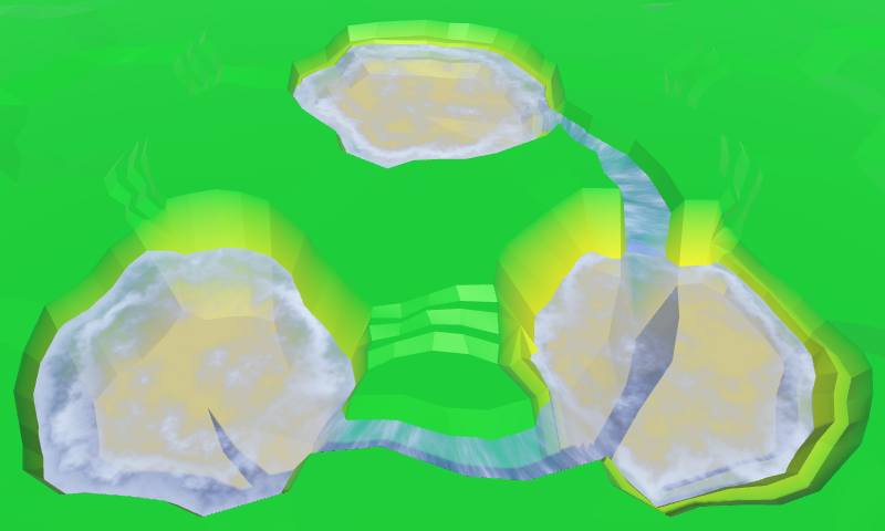
Now the mouths have a good mix between the expanding river, the coastal water and the foam. Although it does not create an exact match with waterfalls, this effect looks good with waterfalls.
Mouth in action
unitypackage
We already have rivers flowing into reservoirs, but there is no support for rivers flowing in a different direction. There are lakes from which rivers flow, so we need to add them too.
When a river flows out of a reservoir, it actually flows towards a greater height. This is currently not possible. We need to make an exception and allow this situation if the water level corresponds to the height of the target point. Let's add to the
We will use our new method to determine whether it is possible to create an outgoing river.
Also there you need to check the river when the height of the cell or water level changes. Create a private method that will take care of this task.
We use this new method in the properties
Outgoing and entering the lakes of the river.
We created
We will transmit this information when calling this method from
Now we need to turn the flow of the river, changing the coordinates of UV2. The coordinates of U for outgoing rivers need to be mirrored: −0.5 becomes 1.5, 0 becomes 1, 1 becomes 0, and 1.5 becomes −0.5.
With V coordinates, things are a little more complicated. If you look at how we worked with inverted connections of rivers, then 0.8 should be 0, and 1 should be −0.2. This means that 1.1 becomes −0.3, and 1.15 becomes −0.35.
Since in each case the coordinates of UV2 are very different, let's write a separate code for them.
The correct flow of the rivers.
unitypackage
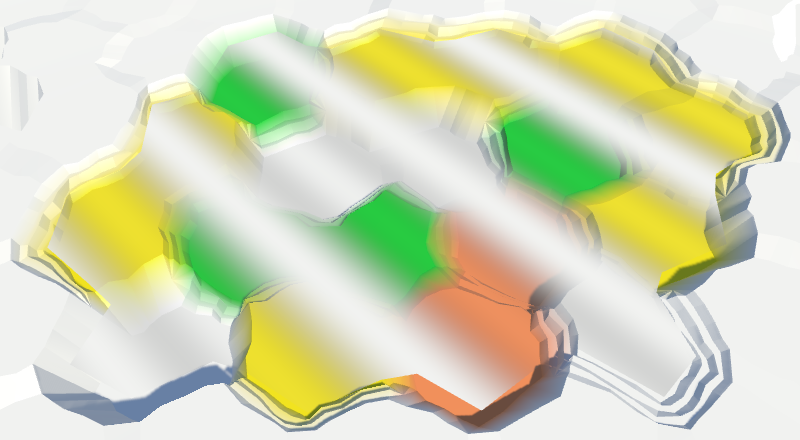
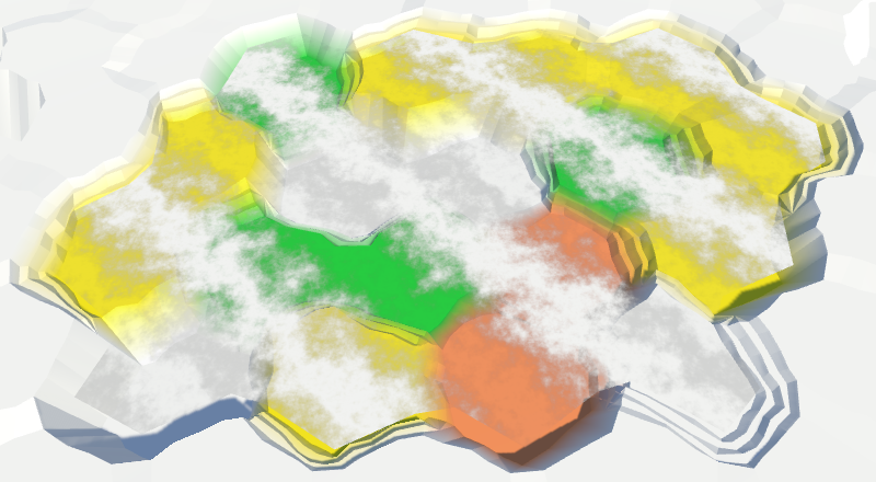
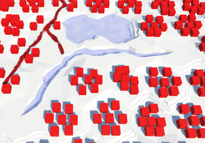
In this part we will talk about adding objects to the relief. We will create objects such as buildings and trees.
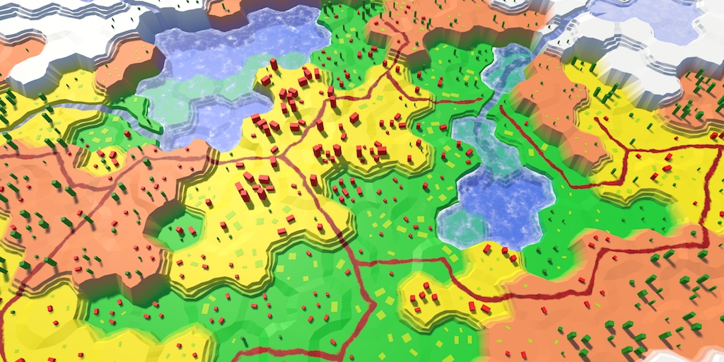
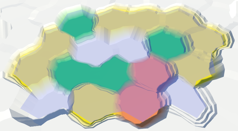
Conflict between forests, agricultural land and urbanization.
Although the shape of the relief has variations, while nothing happens on it. It is a lifeless land. To breathe life into it, you need to add such objects. like trees and houses. These objects are not part of the relief mesh, but will be separate objects. But this will not prevent us from adding them when triangulating the terrain.
Let's create a component
We will start with the implementation-procurement, which so far will not do anything.
Now we can add a link to such a component in
Let's start by placing one object in the center of each cell.
Now we need a real object manager. Add another child to the Hex Grid Chunk prefab and give it a component
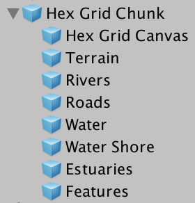
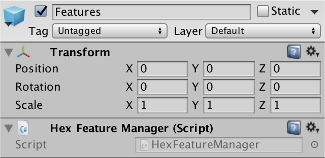
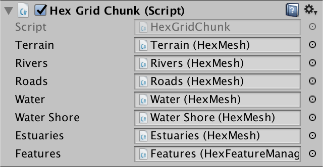
Object manager added to fragment prefab.
What terrain object will we create? For the first test, the cube is quite suitable. Create a sufficiently large cube, for example, with a scale (3, 3, 3), and turn it into a prefab. Also create a material for it. I used the default material with red color. Remove it from the collider, because we do not need it.

Prefab Cube.
Object managers will need a link to this prefab, so add it to
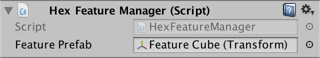
Object manager with prefab.
The structure is ready, and we can begin to add relief objects! Simply create an instance of the prefab in
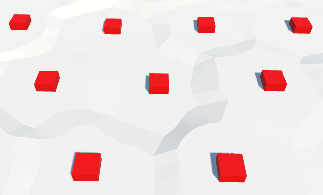
Instances of relief objects.
From this point on, the relief will be filled with cubes. At the very least, the upper halves of the cubes, because the local origin point for the cube mesh in Unity is in the center of the cube, and the lower part is below the surface of the relief. To place the cubes on topography, we need to move them up half their height.
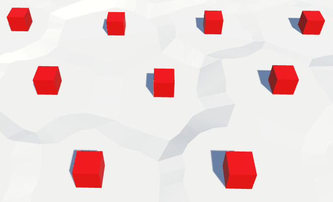
Cubes on the surface of the relief.
Of course, our cells are distorted, so we need to distort the position of objects. So we get rid of the perfect repeatability of the grid.
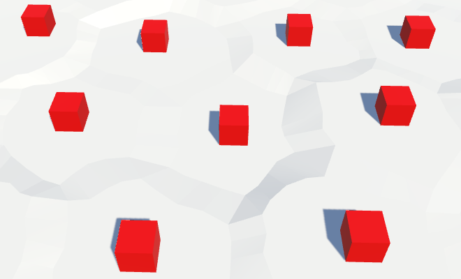
Distorted positions of objects.
With each update of the fragment, we create new relief objects. This means that while we are creating more and more objects in the same positions. To avoid duplicates, we need to get rid of old objects when cleaning up a fragment.
The fastest way to do this is by creating a container game object and turning all the relief objects into its children. Then, when
unitypackage
For now, we place objects in the center of each cell. For empty cells, this looks normal, but on cells containing rivers and roads, as well as flooded with water, it seems strange.
Objects are located everywhere.
Therefore, before placing the object, let's check in
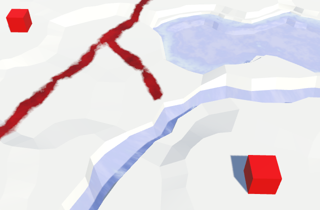
Limited accommodation.
Only one object per cell is not too much. There is plenty of room for heaps of objects. Therefore, we add an additional object to the center of each of the six triangles of the cell, that is, one per direction.
We will do this in another method
Many facilities, but not in the vicinity of the rivers.
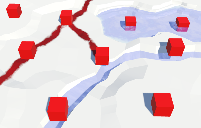
This creates many more objects! They appear alongside the roads, but they still avoid the rivers. To place objects along the rivers, we can also add them inside
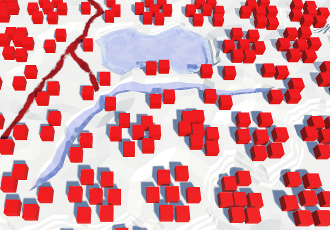
Objects appeared alongside the rivers.
unitypackage
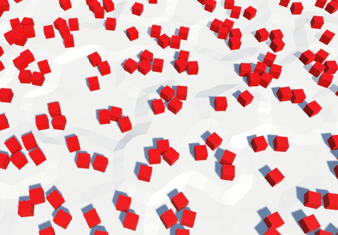
All our relief objects have the same orientation, which looks completely unnatural. Let's give each of them a random turn.

Random turns.
So the result becomes much more diverse. Unfortunately, each time a fragment is updated, objects get a new random rotation. Editing cells should not change the objects in the neighborhood, so we need a different approach.
We have a noise texture that is always the same. However, this texture contains Perlin's gradient noise, and it is locally matched. This is what we need when we distort the positions of the vertices in the cells. But the turns do not have to be coordinated. All turns should be equally probable and mixed. Therefore, we need a texture with non-gradient random values that can be sampled without bilinear filtering. In essence, this is a hash grid that creates the basis of gradient noise.
We can create a hash table from an array of float values and fill it once with random values. Thanks to this, we don’t need a texture at all. Let's add it to
Random values are generated by a mathematical formula that always gives the same results. The resulting sequence depends on the number of seed, which by default is equal to the current time value. That is why in each game session we will receive different results.
To ensure the re-creation of always identical objects, we need to add the seed parameter to the initialization method.
Now that we have initialized the random number stream, we will always get the same sequence from it. Therefore, seemingly random events occurring after the card generation will also always be the same. We can avoid this by maintaining the state of the random number generator before it is initialized. After completing the work, we can ask him the old state.
The hashes table is initialized
The common seed variable allows us to choose the seed value for the card. Any value will do. I chose 1234.
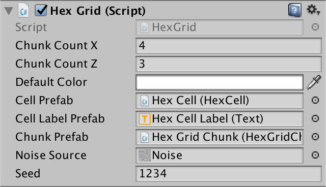
Selection of seed.
To use the hash table, add to the
This works for positive coordinates, but not for negative ones, because for such numbers the remainder will be negative. We can fix this by adding a table size to negative results.
Now for each square unit we create our own value. However, in reality, we do not need such a density table. Objects are separated from each other further. We can stretch the table by reducing the scale of the position before calculating the index. We will need only one unique value for a 4 by 4 square.
Let's go back to
Although objects have a different turn, the pattern is still noticeable in their placement. There are seven objects in each cell. We can add chaos to this scheme by arbitrarily omitting some of the objects. How do we decide whether to add an object or not? Of course, testing another random value!
That is, now instead of a single hash value, we need two. Their support can be added by using a hash table instead of a
Change it
Now
The density of objects is reduced by 50%.
unitypackage
Instead of placing objects everywhere, let's make them editable. But we will not draw separate objects, but add the level of objects to each cell. This level will control the likelihood of objects in the cell. By default, the value is zero, that is, the objects will be absent.
Since red cubes do not look like natural objects on our relief, let's call them buildings. They will represent urbanization. Let's add to the
We can make it so that the level of urbanization for the underwater cell is zero, but this is not necessary, we already skip the creation of underwater objects. And perhaps at some stage we will add water objects of urbanization, such as docks and underwater structures.
To change the level of urbanization, we will add
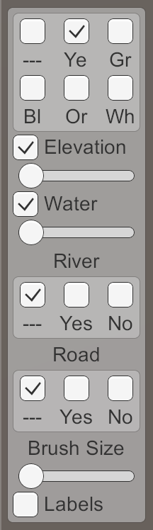
Add another slider to the UI and connect it with the appropriate methods. I will place a new panel on the right side of the screen to avoid overflowing the left panel.
How many levels will we need? Let's look at four that denote zero, low, medium, and high density.

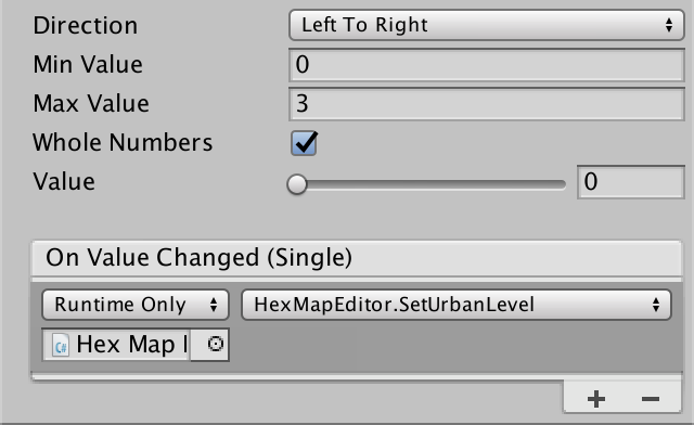
Urbanization slider.
Now that we have a level of urbanization, we need to use it to determine whether to place objects. To do this, we need to add the level of urbanization as an additional parameter in
The fastest way to take advantage of the level of urbanization is by multiplying it by 0.25 and using the value as a new threshold for skipping objects. Due to this, the probability of an object will increase with each level by 25%.
To make it work, pass the cells to
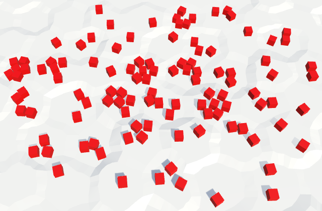
Drawing density levels of urbanization.
unitypackage
The differences in the probability of objects appearing are not enough to create a clear separation between low and high levels of urbanization. In some cells, there will simply be more or less than the expected number of buildings. We can make the difference clearer by using our own prefab for each level.
Let's get rid of the field
We will create two duplicates of the prefab of the object, rename and change them so that they denote three different levels of urbanization. Level 1 is low density, so we use a cube with a unit edge length, which denotes a shack. I will scale the prefab level 2 to (1.5, 2, 1.5) to make it look like a two-story building. For tall buildings of level 3, I used the scale (2, 5, 2).
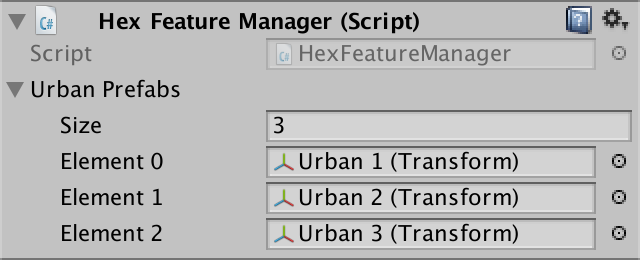
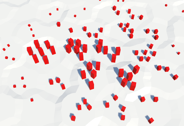
Using different prefabs for each level of urbanization.
We are not obliged to limit ourselves to strict division of building types. You can mix them up a bit, as it happens in the real world. Instead of one threshold per level, let's use three, one for each type of building.
At level 1, we use shackling in 40% of cases. There will be no other buildings here at all. For the level we use three values (0.4, 0, 0).
At level 2, we replace the shacks with more buildings, and add a 20% probability for additional shacks. High buildings will not do. That is, we use the threshold three values (0.2, 0.4, 0).
At level 3, we replace medium buildings with high ones, replace shacks again, and add another probability of 20% shacks. The threshold values will be equal to (0.2, 0.2, 0.4).
That is, the idea is that as the level of urbanization increases, we will upgrade existing buildings and add new ones to empty places. To delete an existing building, we need to use the same hash value intervals. If the hashes between 0 and 0.4 at level 1 were shacks, then at level 3 the same spacing will create tall buildings. At level 3, tall buildings should be created with hash values in the range of 0–0.4, two-story buildings in the range of 0.4–0.6, and shacks in the range of 0.6–0.8. If you check them from highest to lowest, then this can be done with the help of triple thresholds (0.4, 0.6, 0.8). The thresholds of level 2 will then become (0, 0.4, 0.6), and the thresholds of level 1 will become (0, 0, 0.4).
Let's save these thresholds in
Next, add to the
Parts 4-7: bumps, rivers and roads
Parts 8-11: water, objects of the relief and walls of
Parts 12-15: preservation and loading, textures, distances
Parts 16-19: search for the path, player squads, animations
Parts 20-23: fog of war, map exploration, procedural generation
Parts 24-27: water cycle, erosion, biomes, cylindrical map
Part 8: water
- Add water to the cells.
- Triangulate the surface of the water.
- Create a surf with foam.
- Combine water and rivers.
We have already added support for the rivers, and in this part we will completely submerge the cells in water.
Water is coming.
Water level
The easiest way to implement water support is to set it at the same level. All cells below this level are submerged in water. But a more flexible way is to support water at different heights, so let's make the water level changeable. For this you need to
HexCelltrack your water level.publicint WaterLevel {
get {
return waterLevel;
}
set {
if (waterLevel == value) {
return;
}
waterLevel = value;
Refresh();
}
}
int waterLevel;If desired, you can make sure that certain features of the relief do not exist under water. But for now I will not do this. Things like underwater roads suit me. They can be considered areas that have recently been flooded.
Flooding of cells
Now that we have water levels, the most important question is whether the cells are under water. The cell is under water if its water level is higher than its height. To get this information, we will add a property.
publicbool IsUnderwater {
		get {
			return waterLevel > elevation;
		}
	}
This means that when the water level and height are equal, the cell rises above the water. That is, the real surface of the water is below this height. As is the case with river surfaces, let's add the same offset -
HexMetrics.riverSurfaceElevationOffset. Let's change its name to more general.// public const float riverSurfaceElevationOffset = -0.5f;publicconstfloat waterElevationOffset = -0.5f;Change it
HexCell.RiverSurfaceYso that it uses the new name. Then add a similar property to the water surface of the flooded cell.publicfloat RiverSurfaceY {
get {
return
(elevation + HexMetrics.waterElevationOffset) *
HexMetrics.elevationStep;
}
}
publicfloat WaterSurfaceY {
get {
return
(waterLevel + HexMetrics.waterElevationOffset) *
HexMetrics.elevationStep;
}
}Water editing
Editing the water level is similar to changing the height. Therefore, it
HexMapEditormust monitor the active water level and whether it should be applied to cells.int activeElevation;
int activeWaterLevel;
…
bool applyElevation = true;
bool applyWaterLevel = true;
Add methods to connect these parameters with the UI.
publicvoidSetApplyWaterLevel (bool toggle) {
		applyWaterLevel = toggle;
	}
	publicvoidSetWaterLevel (float level) {
		activeWaterLevel = (int)level;
	}
And add the water level in
EditCell.voidEditCell (HexCell cell) {
if (cell) {
if (applyColor) {
cell.Color = activeColor;
}
if (applyElevation) {
cell.Elevation = activeElevation;
}
if (applyWaterLevel) {
cell.WaterLevel = activeWaterLevel;
}
…
}
}To add a water level to the UI, duplicate the label and the height slider, and then change them. Do not forget to attach their events to the appropriate methods.
Water level slider.
unitypackage
Water triangulation
To triangulate water, we need a new mesh with new material. First create the Water shader by duplicating the River shader . Change it to use the color property.
Shader "Custom/Water" {
Properties {
_Color ("Color", Color) = (1,1,1,1)
_MainTex ("Albedo (RGB)", 2D) = "white" {}
_Glossiness ("Smoothness", Range(0,1)) = 0.5
_Metallic ("Metallic", Range(0,1)) = 0.0
}
SubShader {
Tags { "RenderType"="Transparent""Queue"="Transparent" }
LOD 200
CGPROGRAM
#pragma surface surf Standard alpha#pragma target 3.0
sampler2D _MainTex;
struct Input {
float2 uv_MainTex;
};
half _Glossiness;
half _Metallic;
fixed4 _Color;
voidsurf (Input IN, inout SurfaceOutputStandard o) {
fixed4 c = _Color;
o.Albedo = c.rgb;
o.Metallic = _Metallic;
o.Smoothness = _Glossiness;
o.Alpha = c.a;
}
ENDCG
}
FallBack "Diffuse"
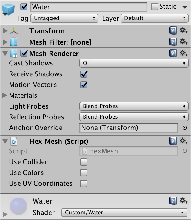
}Create a new material with this shader by duplicating the Water material and replacing it with a shader. Let's leave the noise texture, because later we use it.
Material Water.
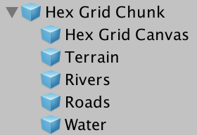
Add a new child to the prefab by duplicating the Rivers child . It does not need UV coordinates, and it must use Water . As usual, let's do this by creating an instance of the prefab, changing it, and then applying the changes to the prefab. After that, get rid of the instance.
Child Water object.
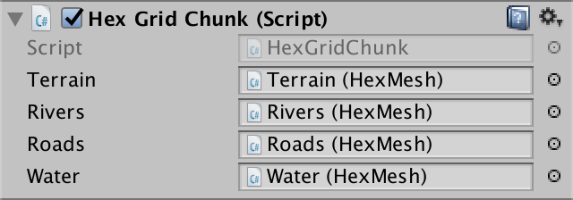
Next, add in the
HexGridChunksupport mesh water.public HexMesh terrain, rivers, roads, water;
publicvoidTriangulate () {
terrain.Clear();
rivers.Clear();
roads.Clear();
water.Clear();
for (int i = 0; i < cells.Length; i++) {
Triangulate(cells[i]);
}
terrain.Apply();
rivers.Apply();
roads.Apply();
water.Apply();
}And connect it with the child object of the prefab.
Water object is connected.
Water hexagons
Since water forms the second layer, let's give it its own triangulation method for each of the directions. We only need to call it when the cell is immersed in water.
voidTriangulate (HexDirection direction, HexCell cell) {
		…
		if (cell.IsUnderwater) {
			TriangulateWater(direction, cell, center);
		}
	}
	voidTriangulateWater (
		HexDirection direction, HexCell cell, Vector3 center
	) {
	}
As in the case of rivers, the height of the water surface does not vary much in cells with the same water level. Therefore, we do not seem to need complex edges. A simple triangle is enough.
voidTriangulateWater (
		HexDirection direction, HexCell cell, Vector3 center
	) {
		center.y = cell.WaterSurfaceY;
		Vector3 c1 = center + HexMetrics.GetFirstSolidCorner(direction);
		Vector3 c2 = center + HexMetrics.GetSecondSolidCorner(direction);
		water.AddTriangle(center, c1, c2);
	}
Hexagons of water.
Water connections
We can connect adjacent cells with water with one quadrilateral.
		water.AddTriangle(center, c1, c2);
		if (direction <= HexDirection.SE) {
			HexCell neighbor = cell.GetNeighbor(direction);
			if (neighbor == null || !neighbor.IsUnderwater) {
				return;
			}
			Vector3 bridge = HexMetrics.GetBridge(direction);
			Vector3 e1 = c1 + bridge;
			Vector3 e2 = c2 + bridge;
			water.AddQuad(c1, c2, e1, e2);
		}
Joining the edges of the water.
And fill the corners with one triangle.
if (direction <= HexDirection.SE) {
			…
			water.AddQuad(c1, c2, e1, e2);
			if (direction <= HexDirection.E) {
				HexCell nextNeighbor = cell.GetNeighbor(direction.Next());
				if (nextNeighbor == null || !nextNeighbor.IsUnderwater) {
					return;
				}
				water.AddTriangle(
					c2, e2, c2 + HexMetrics.GetBridge(direction.Next())
				);
			}
		}
Connection angles of water.
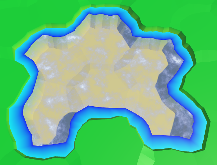
Now we have water cells connected when they are nearby. They leave a gap between themselves and dry cells with greater height, but we will leave that for later.
Matched water levels
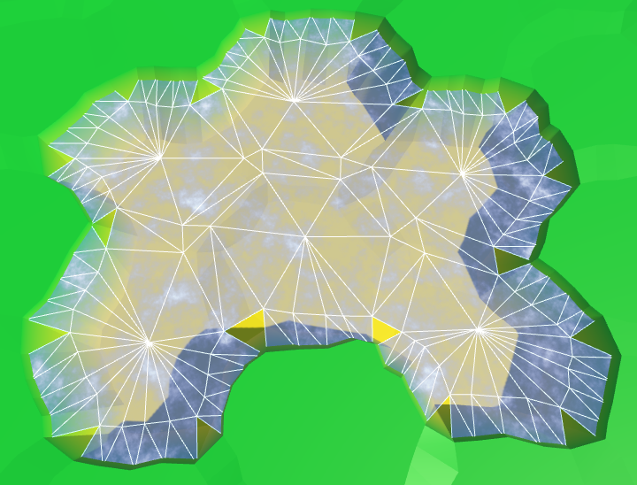
We assumed that the neighboring submarine cells have the same water level. If it is, then everything looks good, but if this assumption is violated, then errors occur.
Inconsistent water levels.
We can make water stay at the same level. For example, if the water level of a flooded cell changes, we can spread the changes to neighboring cells to keep the levels in sync. However, this process must continue until it encounters cells that are not immersed in water. These cells set the boundaries of the water body.
The danger of this approach is that it can quickly get out of control. If editing is unsuccessful, water can cover the entire map. Then all fragments will have to be triangulated at the same time, which will lead to a huge jump in delays.
So let's not do it yet. This function can be added in a more complex editor. As long as the consistency of water levels, we leave on the conscience of the user.
unitypackage
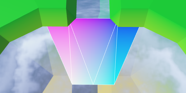
Animating water
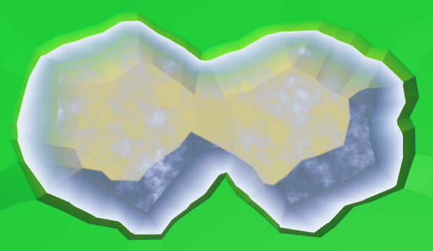
Instead of a uniform color, we will create something resembling a wave. As in other shaders, we still will not strive for beautiful graphics, we only need to designate the waves.
Perfectly flat water.
Let's do the same thing we did with the rivers. Let's sample the noise with the position of the world and add it to the uniform color. To animate the surface, add time to the V coordinate.
		struct Input {
			float2 uv_MainTex;
			float3 worldPos;
		};
		…
		void surf (InputIN, inout SurfaceOutputStandard o) {
			float2 uv = IN.worldPos.xz;
			uv.y += _Time.y;
			float4 noise = tex2D(_MainTex, uv * 0.025);
			float waves = noise.z;
			fixed4 c = saturate(_Color + waves);
			o.Albedo = c.rgb;
			o.Metallic = _Metallic;
			o.Smoothness = _Glossiness;
			o.Alpha = c.a;
		}
Water scrolling, time × 10.
Two directions
So far this is not at all like waves. Let's complicate the picture by adding a second sample of noise
and this time adding the U coordinate. Use another noise channel to get two different patterns as a result. The finished waves will be these two samples stacked together.
			float2 uv1 = IN.worldPos.xz;
			uv1.y += _Time.y;
			float4 noise1 = tex2D(_MainTex, uv1 * 0.025);
			float2 uv2 = IN.worldPos.xz;
			uv2.x += _Time.y;
			float4 noise2 = tex2D(_MainTex, uv2 * 0.025);
			float waves = noise1.z + noise2.x;
When summing both samples, we get results in the range of 0–2, so we need to scale it back to 0–1. Instead of simply dividing the waves in half, we can use the function
smoothstepto create a more interesting result. We will impose ¾ – 2 on 0–1, so that there are no visible waves on the surface of the water.float waves = noise1.z + noise2.x;
waves = smoothstep(0.75, 2, waves);Two directions, time × 10.
Waves of mixing
It is still noticeable that we have two moving noise patterns that do not actually change. It would be plausible if the patterns were changed. We can accomplish this by performing interpolation between different channels of noise samples. But this cannot be done in the same way, otherwise the entire surface of the water will change simultaneously, and this is very noticeable. Instead, we will create a wave of mixing.
We will create a mixing wave using a sine wave that moves diagonally across the surface of the water. We will do this by adding the coordinates of the world X and Z and using the sum as the input data for the function
sin. Zoom out to get large enough bands. And of course, add the same value to animate them.float blendWave =
sin((IN.worldPos.x + IN.worldPos.z) * 0.1 + _Time.y);Sinusoids range from -1 and 1, and we need an interval of 0–1. You can get it by squaring the wave. To see the isolated result, use it instead of the changed color as the output value.
sin((IN.worldPos.x + IN.worldPos.z) * 0.1 + _Time.y);
blendWave *= blendWave;
float waves = noise1.z + noise2.x;
			waves = smoothstep(0.75, 2, waves);
fixed4 c = blendWave; //saturate(_Color + waves);Waves of confusion.
To make blending waves less noticeable, let's add a bit of noise from both samples to them.
float blendWave = sin(
				(IN.worldPos.x + IN.worldPos.z) * 0.1 +
				(noise1.y + noise2.z) + _Time.y
			);
			blendWave *= blendWave;
Distorted mixing waves.
Finally, use a mixing wave to interpolate between the two channels of both noise samples. For maximum variability, take four different channels.
float waves =
lerp(noise1.z, noise1.w, blendWave) +
lerp(noise2.x, noise2.y, blendWave);
waves = smoothstep(0.75, 2, waves);
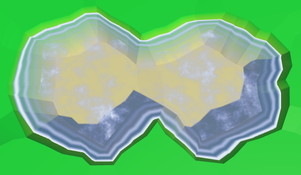
fixed4 c = saturate(_Color + waves);Wave mixing, time × 2.
unitypackage
Coast
We ended up with open water, but now we need to fill the gap in the water along the coast. Since we have to comply with the land contours, the water of the coast requires a different approach. Let's divide
TriangulateWaterinto two methods - one for open water, the second for the coast. To understand when we work with the coast, we need to look at the next cell. That is, in TriangulateWaterwe will receive a neighbor. If there is a neighbor and he is not under water, then we are dealing with the coast.voidTriangulateWater (
HexDirection direction, HexCell cell, Vector3 center
) {
center.y = cell.WaterSurfaceY;
HexCell neighbor = cell.GetNeighbor(direction);
if (neighbor != null && !neighbor.IsUnderwater) {
TriangulateWaterShore(direction, cell, neighbor, center);
}
else {
TriangulateOpenWater(direction, cell, neighbor, center);
}
}
voidTriangulateOpenWater (
HexDirection direction, HexCell cell, HexCell neighbor, Vector3 center
) {
Vector3 c1 = center + HexMetrics.GetFirstSolidCorner(direction);
Vector3 c2 = center + HexMetrics.GetSecondSolidCorner(direction);
water.AddTriangle(center, c1, c2);
if (direction <= HexDirection.SE && neighbor != null) {
// HexCell neighbor = cell.GetNeighbor(direction);// if (neighbor == null || !neighbor.IsUnderwater) {// return;// }
Vector3 bridge = HexMetrics.GetBridge(direction);
…
}
}
voidTriangulateWaterShore (
HexDirection direction, HexCell cell, HexCell neighbor, Vector3 center
) {
}There is no triangulation along the coast.
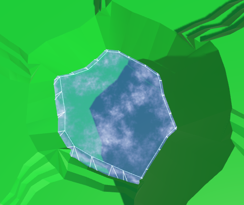
Since the coast is distorted, we must distort the triangles of water along the coast. Therefore, we need vertices of edges and a fan of triangles.
voidTriangulateWaterShore (
		HexDirection direction, HexCell cell, HexCell neighbor, Vector3 center
	) {
		EdgeVertices e1 = new EdgeVertices(
			center + HexMetrics.GetFirstSolidCorner(direction),
			center + HexMetrics.GetSecondSolidCorner(direction)
		);
		water.AddTriangle(center, e1.v1, e1.v2);
		water.AddTriangle(center, e1.v2, e1.v3);
		water.AddTriangle(center, e1.v3, e1.v4);
		water.AddTriangle(center, e1.v4, e1.v5);
	}
Fan triangles along the coast.
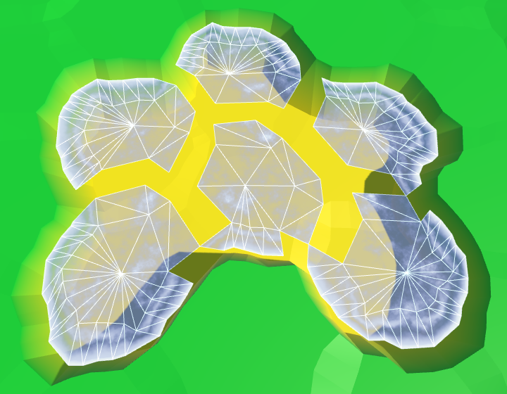
Next comes a strip of ribs, as in the usual relief. However, we are not obliged to limit ourselves only to certain directions, because we
TriangulateWaterShoreonly call when we meet with the coast, for which the strip is always needed. water.AddTriangle(center, e1.v4, e1.v5);
Vector3 bridge = HexMetrics.GetBridge(direction);
EdgeVertices e2 = new EdgeVertices(
e1.v1 + bridge,
e1.v5 + bridge
);
water.AddQuad(e1.v1, e1.v2, e2.v1, e2.v2);
water.AddQuad(e1.v2, e1.v3, e2.v2, e2.v3);
water.AddQuad(e1.v3, e1.v4, e2.v3, e2.v4);
water.AddQuad(e1.v4, e1.v5, e2.v4, e2.v5);Stripes of ribs along the coast.
Similarly, we must also add an angular triangle each time.
		water.AddQuad(e1.v4, e1.v5, e2.v4, e2.v5);
		HexCell nextNeighbor = cell.GetNeighbor(direction.Next());
		if (nextNeighbor != null) {
			water.AddTriangle(
				e1.v5, e2.v5, e1.v5 + HexMetrics.GetBridge(direction.Next())
			);
		}
The angles of the ribs along the coast.
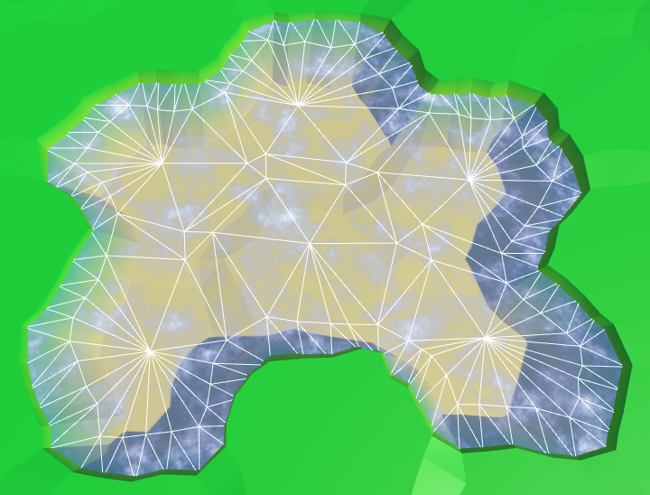
Now we have ready water coast. A part of it is always below the relief mesh, so there are no holes.
UV coast
We can leave everything as it is, but it would be interesting if the coastal water had its own schedule. For example, the effect of foam, which becomes larger when approaching the coast. To implement it, the shader must know how close the fragment is to the coast. We can transmit this information via UV coordinates.
Open water does not have UV coordinates, and does not need foam. It is needed only for water near the coast. Therefore, the requirements for both types of water are quite different. It will be logical to create your own mesh for each type. Therefore, we add
HexGridChunkone more mesh object to support it.public HexMesh terrain, rivers, roads, water, waterShore;
publicvoidTriangulate () {
terrain.Clear();
rivers.Clear();
roads.Clear();
water.Clear();
waterShore.Clear();
for (int i = 0; i < cells.Length; i++) {
Triangulate(cells[i]);
}
terrain.Apply();
rivers.Apply();
roads.Apply();
water.Apply();
waterShore.Apply();
}This new mesh will use
TriangulateWaterShore.voidTriangulateWaterShore (
HexDirection direction, HexCell cell, HexCell neighbor, Vector3 center
) {
…
waterShore.AddQuad(e1.v1, e1.v2, e2.v1, e2.v2);
waterShore.AddQuad(e1.v2, e1.v3, e2.v2, e2.v3);
waterShore.AddQuad(e1.v3, e1.v4, e2.v3, e2.v4);
waterShore.AddQuad(e1.v4, e1.v5, e2.v4, e2.v5);
HexCell nextNeighbor = cell.GetNeighbor(direction.Next());
if (nextNeighbor != null) {
waterShore.AddTriangle(
e1.v5, e2.v5, e1.v5 + HexMetrics.GetBridge(direction.Next())
);
}
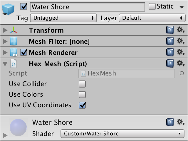
}Duplicate the water object, connect it with the prefab and configure it so that it uses the UV coordinates. We will also create a shader and material for coastal water, duplicating the existing shader and water material.
Water shore object and material with UV.
Change the Water Shore shader so that instead of water it displays the UV coordinates.
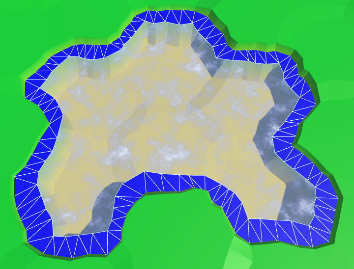
fixed4 c = fixed4(IN.uv_MainTex, 1, 1);Since the coordinates are not yet specified, it will display a solid color. This makes it easy to see that the coast actually uses a separate mesh with material.
Separate mesh for the coast.
Let's put information about the coast in the coordinate V. On the water side, we assign it a value of 0, on the land side - a value of 1. Since we don’t need to transmit anything more, all U coordinates will simply be 0.
		waterShore.AddQuad(e1.v1, e1.v2, e2.v1, e2.v2);
		waterShore.AddQuad(e1.v2, e1.v3, e2.v2, e2.v3);
		waterShore.AddQuad(e1.v3, e1.v4, e2.v3, e2.v4);
		waterShore.AddQuad(e1.v4, e1.v5, e2.v4, e2.v5);
		waterShore.AddQuadUV(0f, 0f, 0f, 1f);
		waterShore.AddQuadUV(0f, 0f, 0f, 1f);
		waterShore.AddQuadUV(0f, 0f, 0f, 1f);
		waterShore.AddQuadUV(0f, 0f, 0f, 1f);
		HexCell nextNeighbor = cell.GetNeighbor(direction.Next());
		if (nextNeighbor != null) {
			waterShore.AddTriangle(
				e1.v5, e2.v5, e1.v5 + HexMetrics.GetBridge(direction.Next())
			);
			waterShore.AddTriangleUV(
				new Vector2(0f, 0f),
				new Vector2(0f, 1f),
				new Vector2(0f, 0f)
			);
		}
Transitions to the coasts, wrong.
The above code works for edges, but is erroneous in some angles. If the next neighbor is under water, then this approach will be correct. But when the next neighbor is not under water, the third vertex of the triangle will be under dry land.
			waterShore.AddTriangleUV(
				new Vector2(0f, 0f),
				new Vector2(0f, 1f),
				new Vector2(0f, nextNeighbor.IsUnderwater ? 0f : 1f)
			);
Transitions to the coasts, correct.
Foam on the coast
Now that the transitions to the coast have been implemented correctly, you can use them to create a foam effect. The easiest way to add the value of the coast to a uniform color.
void surf (InputIN, inout SurfaceOutputStandard o) {
			float shore = IN.uv_MainTex.y;
			float foam = shore;
			fixed4 c = saturate(_Color + foam);
			o.Albedo = c.rgb;
			o.Metallic = _Metallic;
			o.Smoothness = _Glossiness;
			o.Alpha = c.a;
		}
Linear foam.
To make the foam more interesting, multiply it by the square of the sine wave.
float foam = sin(shore * 10);
			foam *= foam * shore;
Fading square sinusoid foam.
Let's make the foam front bigger as we get closer to the shore. This can be done by taking its square root before using the value of the coast.
float shore = IN.uv_MainTex.y;
			shore = sqrt(shore);
Foam becomes thicker near the shore.
Add distortion to make it look more natural. Let us make it so that when approaching the shore, the distortion becomes weaker. So it will better fit the coastline.
			float2 noiseUV = IN.worldPos.xz;
			float4 noise = tex2D(_MainTex, noiseUV * 0.015);
			float distortion = noise.x * (1 - shore);
			float foam = sin((shore + distortion) * 10);
			foam *= foam * shore;
Distorted foam.
And, of course, all this is animated: both a sine wave and distortion.
			float2 noiseUV = IN.worldPos.xz + _Time.y * 0.25;
			float4 noise = tex2D(_MainTex, noiseUV * 0.015);
			float distortion = noise.x * (1 - shore);
			float foam = sin((shore + distortion) * 10 - _Time.y);
			foam *= foam * shore;
Animated foam.
In addition to foam arriving, there is a retreating. Let's add a second sinusoid for its simulation, which moves in the opposite direction. Make it weaker and add a time shift. The finished foam will be the maximum of these two sinusoids.
float distortion1 = noise.x * (1 - shore);
			float foam1 = sin((shore + distortion1) * 10 - _Time.y);
			foam1 *= foam1;
			float distortion2 = noise.y * (1 - shore);
			float foam2 = sin((shore + distortion2) * 10 + _Time.y + 2);
			foam2 *= foam2 * 0.7;
			float foam = max(foam1, foam2) * shore;
Inbound and receding foam.
Mixing waves and foam
There is a sharp transition between open and coastal waters, because open water waves are not included in the coastal waters. To fix this, we need to include these waves in the Water Shore shader .
Instead of copying the code of the waves, let's paste it into the Water.cginc include file . In fact, we insert code for foam and for waves, each as a separate function.
How do shader include files work?
Создание собственных include-файлов шейдеров рассматривается в туториале Rendering 5, Multiple Lights.
float Foam (float shore, float2 worldXZ, sampler2D noiseTex) {
//	float shore = IN.uv_MainTex.y;
	shore = sqrt(shore);
	float2 noiseUV = worldXZ + _Time.y * 0.25;
	float4 noise = tex2D(noiseTex, noiseUV * 0.015);
	float distortion1 = noise.x * (1 - shore);
	float foam1 = sin((shore + distortion1) * 10 - _Time.y);
	foam1 *= foam1;
	float distortion2 = noise.y * (1 - shore);
	float foam2 = sin((shore + distortion2) * 10 + _Time.y + 2);
	foam2 *= foam2 * 0.7;
	return max(foam1, foam2) * shore;
}
float Waves (float2 worldXZ, sampler2D noiseTex) {
	float2 uv1 = worldXZ;
	uv1.y += _Time.y;
	float4 noise1 = tex2D(noiseTex, uv1 * 0.025);
	float2 uv2 = worldXZ;
	uv2.x += _Time.y;
	float4 noise2 = tex2D(noiseTex, uv2 * 0.025);
	float blendWave = sin(
		(worldXZ.x + worldXZ.y) * 0.1 +
		(noise1.y + noise2.z) + _Time.y
	);
	blendWave *= blendWave;
	float waves =
		lerp(noise1.z, noise1.w, blendWave) +
		lerp(noise2.x, noise2.y, blendWave);
	return smoothstep(0.75, 2, waves);
}
Change the Water shader to use the new include file.
		#include "Water.cginc"
		sampler2D _MainTex;
		…
		void surf (InputIN, inout SurfaceOutputStandard o) {
			float waves = Waves(IN.worldPos.xz, _MainTex);
			fixed4 c = saturate(_Color + waves);
			o.Albedo = c.rgb;
			o.Metallic = _Metallic;
			o.Smoothness = _Glossiness;
			o.Alpha = c.a;
		}
The Water Shore shader calculates values for both foam and waves. Then we mute the waves as we approach the shore. The finished result will be a maximum of foam and waves.
		#include "Water.cginc"
		sampler2D _MainTex;
		…
		void surf (InputIN, inout SurfaceOutputStandard o) {
			float shore = IN.uv_MainTex.y;
			float foam = Foam(shore, IN.worldPos.xz, _MainTex);
			float waves = Waves(IN.worldPos.xz, _MainTex);
			waves *= 1 - shore;
			fixed4 c = saturate(_Color + max(foam, waves));
			o.Albedo = c.rgb;
			o.Metallic = _Metallic;
			o.Smoothness = _Glossiness;
			o.Alpha = c.a;
		}
Mixing foam and waves.
unitypackage
Again about coastal water
Part of the coastal mesh is hidden under the mesh of the relief. This is normal, but only a small part is hidden. Unfortunately, steep cliffs hide most of the coastal water, and therefore foam.
Almost hidden coastal water.
We can handle this by increasing the size of the coastline. This can be done by reducing the radius of the hexagons of water. For this, in addition to the integrity coefficient, we need
HexMetricsa water ratio, as well as methods for obtaining water angles. Integrity factor is 0.8. To double the size of the water compounds, we need to assign a value of 0.6 to the water coefficient.
publicconstfloat waterFactor = 0.6f;
	publicstatic Vector3 GetFirstWaterCorner (HexDirection direction) {
		return corners[(int)direction] * waterFactor;
	}
	publicstatic Vector3 GetSecondWaterCorner (HexDirection direction) {
		return corners[(int)direction + 1] * waterFactor;
	}
We use these new methods
HexGridChunkto find the angles of the water.voidTriangulateOpenWater (
HexDirection direction, HexCell cell, HexCell neighbor, Vector3 center
) {
Vector3 c1 = center + HexMetrics.GetFirstWaterCorner(direction);
Vector3 c2 = center + HexMetrics.GetSecondWaterCorner(direction);
…
}
voidTriangulateWaterShore (
HexDirection direction, HexCell cell, HexCell neighbor, Vector3 center
) {
EdgeVertices e1 = new EdgeVertices(
center + HexMetrics.GetFirstWaterCorner(direction),
center + HexMetrics.GetSecondWaterCorner(direction)
);
…
}Using angles of water.
The distance between the hexagons of water has indeed doubled. Now
HexMetricsalso should have a method of creating bridges in the water.publicconstfloat waterBlendFactor = 1f - waterFactor;
publicstatic Vector3 GetWaterBridge (HexDirection direction) {
return (corners[(int)direction] + corners[(int)direction + 1]) *
waterBlendFactor;
}Let's change it
HexGridChunkso that it uses the new method.voidTriangulateOpenWater (
HexDirection direction, HexCell cell, HexCell neighbor, Vector3 center
) {
…
if (direction <= HexDirection.SE && neighbor != null) {
Vector3 bridge = HexMetrics.GetWaterBridge(direction);
…
if (direction <= HexDirection.E) {
…
water.AddTriangle(
c2, e2, c2 + HexMetrics.GetWaterBridge(direction.Next())
);
}
}
}
voidTriangulateWaterShore (
HexDirection direction, HexCell cell, HexCell neighbor, Vector3 center
) {
…
Vector3 bridge = HexMetrics.GetWaterBridge(direction);
…
HexCell nextNeighbor = cell.GetNeighbor(direction.Next());
if (nextNeighbor != null) {
waterShore.AddTriangle(
e1.v5, e2.v5, e1.v5 +
HexMetrics.GetWaterBridge(direction.Next())
);
…
}
}Long bridges in the water.
Between the ribs of water and land
Although this gives us more space for the foam, now even more is hidden under the relief. Ideally, we will be able to use the water edge from the water side, and the land edge from the land side.
We cannot use a simple bridge to find the opposite edge of the land, if we start from the corners of the water. Instead, we can go in the opposite direction, from the center of the neighbor. Modify
TriangulateWaterShoreto use this new approach.// Vector3 bridge = HexMetrics.GetWaterBridge(direction);
Vector3 center2 = neighbor.Position;
center2.y = center.y;
EdgeVertices e2 = new EdgeVertices(
center2 + HexMetrics.GetSecondSolidCorner(direction.Opposite()),
center2 + HexMetrics.GetFirstSolidCorner(direction.Opposite())
);
…
HexCell nextNeighbor = cell.GetNeighbor(direction.Next());
if (nextNeighbor != null) {
Vector3 center3 = nextNeighbor.Position;
center3.y = center.y;
waterShore.AddTriangle(
e1.v5, e2.v5, center3 +
HexMetrics.GetFirstSolidCorner(direction.Previous())
);
…
}Wrong corners of edges.
It worked, but now we again need to consider two cases for corner triangles.
		HexCell nextNeighbor = cell.GetNeighbor(direction.Next());
		if (nextNeighbor != null) {
//			Vector3 center3 = nextNeighbor.Position;//			center3.y = center.y;
			Vector3 v3 = nextNeighbor.Position + (nextNeighbor.IsUnderwater ?
				HexMetrics.GetFirstWaterCorner(direction.Previous()) :
				HexMetrics.GetFirstSolidCorner(direction.Previous()));
			v3.y = center.y;
			waterShore.AddTriangle(e1.v5, e2.v5, v3);
			waterShore.AddTriangleUV(
				new Vector2(0f, 0f),
				new Vector2(0f, 1f),
				new Vector2(0f, nextNeighbor.IsUnderwater ? 0f : 1f)
			);
		}
The correct angles of the edges.
It worked well, but now that most of the foam is visible, it becomes quite pronounced. To compensate for this, we will make the effect a bit weaker, reducing the scale of the coast in the shader.
shore = sqrt(shore) * 0.9;Ready foam.
unitypackage
Submarine rivers
We ended up with water, at least in those places where rivers do not flow into it. Since water and rivers do not notice each other yet, rivers will flow through and under the water.
Rivers flowing in water.
The order in which translucent objects are rendered depends on their distance from the camera. The closest objects are rendered last, so they are at the top. When you move the camera, this will mean that sometimes rivers and sometimes water will appear over each other. Let's start by making the rendering order constant. Rivers must be drawn on top of the water so that waterfalls are displayed correctly. We can accomplish this by changing the River shader's queue .
Tags { "RenderType"="Transparent""Queue"="Transparent+1" }Draw the river last.
Hiding underwater rivers
Although the river bed may well be under water, and water can actually flow through it, we should not see this water. And even more so it should not be rendered on top of the real surface of the water. We can get rid of the water of submarine rivers by adding river segments only when the current cell is not under water.
voidTriangulateWithRiverBeginOrEnd (
		HexDirection direction, HexCell cell, Vector3 center, EdgeVertices e
	) {
		…
		if (!cell.IsUnderwater) {
			bool reversed = cell.HasIncomingRiver;
			…
		}
	}
	voidTriangulateWithRiver (
		HexDirection direction, HexCell cell, Vector3 center, EdgeVertices e
	) {
		…
		if (!cell.IsUnderwater) {
			bool reversed = cell.IncomingRiver == direction;
			…
		}
	}
To
TriangulateConnectionbegin, we will add a segment of the river, when neither the current nor the neighboring cell is under water.if (cell.HasRiverThroughEdge(direction)) {
e2.v3.y = neighbor.StreamBedY;
if (!cell.IsUnderwater && !neighbor.IsUnderwater) {
TriangulateRiverQuad(
e1.v2, e1.v4, e2.v2, e2.v4,
cell.RiverSurfaceY, neighbor.RiverSurfaceY, 0.8f,
cell.HasIncomingRiver && cell.IncomingRiver == direction
);
}
}No more submarine rivers.
Waterfalls
There are no more submarine rivers, but now we have holes in those parts of the rivers where they meet the surface of the water. Rivers flush with water create small holes or overlaps. But the most noticeable are the missing waterfalls for rivers flowing from a greater height. Let's do it first.
The river segment with a waterfall used to pass through the surface of the water. As a result, it was partially over, and partly under water. We need to keep a part above the water level, discarding everything else. We have to work hard for this, so we will create a separate method.
The new method requires four peaks, two levels of rivers and water level. We will set it up so that we look in the direction of the current, down the waterfall. Therefore, the first two vertices and the left and right sides will be on top, followed by the lower ones.
voidTriangulateWaterfallInWater (
		Vector3 v1, Vector3 v2, Vector3 v3, Vector3 v4,
		float y1, float y2, float waterY
	) {
		v1.y = v2.y = y1;
		v3.y = v4.y = y2;
		rivers.AddQuad(v1, v2, v3, v4);
		rivers.AddQuadUV(0f, 1f, 0.8f, 1f);
	}
Let's call this method in
TriangulateConnection, when a neighbor is under water and we are creating a waterfall.if (!cell.IsUnderwater) {
if (!neighbor.IsUnderwater) {
TriangulateRiverQuad(
e1.v2, e1.v4, e2.v2, e2.v4,
cell.RiverSurfaceY, neighbor.RiverSurfaceY, 0.8f,
cell.HasIncomingRiver && cell.IncomingRiver == direction
);
}
elseif (cell.Elevation > neighbor.WaterLevel) {
TriangulateWaterfallInWater(
e1.v2, e1.v4, e2.v2, e2.v4,
cell.RiverSurfaceY, neighbor.RiverSurfaceY,
neighbor.WaterSurfaceY
);
}
}We also need to process waterfalls in the opposite direction, when the current cell is under water and the next cell is not.
if (!cell.IsUnderwater) {
				…
			}
			elseif (
				!neighbor.IsUnderwater &&
				neighbor.Elevation > cell.WaterLevel
			) {
				TriangulateWaterfallInWater(
					e2.v4, e2.v2, e1.v4, e1.v2,
					neighbor.RiverSurfaceY, cell.RiverSurfaceY,
					cell.WaterSurfaceY
				);
			}
So we again get the quad of the source river. Next, we need to change
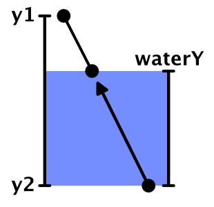
TriangulateWaterfallInWaterso that it raises the lower peaks to the water level. Unfortunately, changing only the Y coordinates will not be enough. This can move the waterfall away from the cliff, which may cause holes to form. Instead, you have to move the bottom vertices to the top using interpolation.We interpolate.
To move the lower peaks up, divide their distance below the water surface by the height of the waterfall. This will give us the value of the interpolator.
		v1.y = v2.y = y1;
		v3.y = v4.y = y2;
		float t = (waterY - y2) / (y1 - y2);
		v3 = Vector3.Lerp(v3, v1, t);
		v4 = Vector3.Lerp(v4, v2, t);
		rivers.AddQuad(v1, v2, v3, v4);
		rivers.AddQuadUV(0f, 1f, 0.8f, 1f);
As a result, we get a shortened waterfall, having the same orientation. However, since the positions of the lower vertices have changed, they are distorted not in the same way as the original vertices. This means that the end result will still not coincide with the original waterfall. To solve this problem, we need to manually distort the vertices before interpolation, and then add an undistorted quad.
		v1.y = v2.y = y1;
		v3.y = v4.y = y2;
		v1 = HexMetrics.Perturb(v1);
		v2 = HexMetrics.Perturb(v2);
		v3 = HexMetrics.Perturb(v3);
		v4 = HexMetrics.Perturb(v4);
		float t = (waterY - y2) / (y1 - y2);
		v3 = Vector3.Lerp(v3, v1, t);
		v4 = Vector3.Lerp(v4, v2, t);
		rivers.AddQuadUnperturbed(v1, v2, v3, v4);
		rivers.AddQuadUV(0f, 1f, 0.8f, 1f);
Since we already have a method for adding undistorted triangles, we really do not need to create it for quad-s. Therefore, we add the required method
HexMesh.AddQuadUnperturbed.publicvoidAddQuadUnperturbed (
Vector3 v1, Vector3 v2, Vector3 v3, Vector3 v4
) {
int vertexIndex = vertices.Count;
vertices.Add(v1);
vertices.Add(v2);
vertices.Add(v3);
vertices.Add(v4);
triangles.Add(vertexIndex);
triangles.Add(vertexIndex + 2);
triangles.Add(vertexIndex + 1);
triangles.Add(vertexIndex + 1);
triangles.Add(vertexIndex + 2);
triangles.Add(vertexIndex + 3);
}Waterfalls end on the surface of the water.
unitypackage
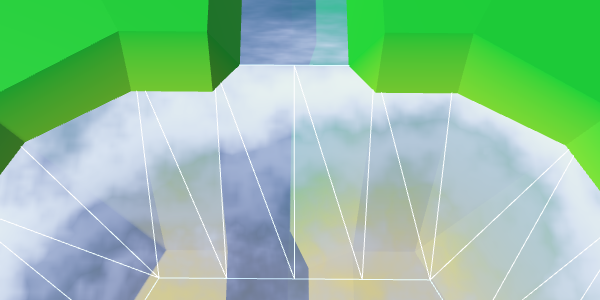
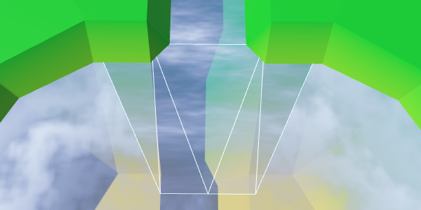
Estuary
When rivers flow at the same height as the surface of the water, the mesh of the river touches the mesh of the coast. If it were a river flowing into the sea or into the ocean, then there would be a current of the river with a surf. Therefore, we will call these areas mouths.
The river meets the coast without distorting the peaks.
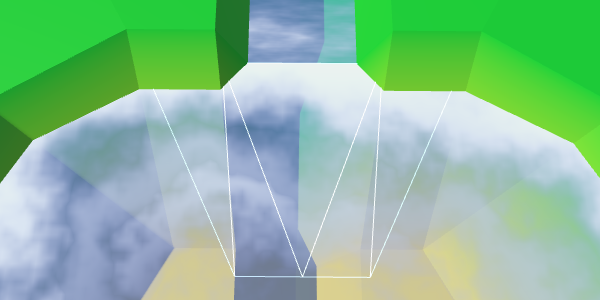
Now we have two problems with the mouths. Firstly, quad rivers join the second and fourth tops of the ribs, passing the third. Since the coast of water does not use the third peak, it can create a hole or overlap. We can solve this problem by changing the mouth geometry.
The second problem is that there is a sharp transition between foam and river materials. To solve it, we need another material that mixes the effects of the river and water.
This means that the mouths require a special approach, so let's create a separate method for them. It should be called in
TriangulateWaterShorewhen there is a river moving in the current direction.voidTriangulateWaterShore (
HexDirection direction, HexCell cell, HexCell neighbor, Vector3 center
) {
…
if (cell.HasRiverThroughEdge(direction)) {
TriangulateEstuary(e1, e2);
}
else {
waterShore.AddQuad(e1.v1, e1.v2, e2.v1, e2.v2);
waterShore.AddQuad(e1.v2, e1.v3, e2.v2, e2.v3);
waterShore.AddQuad(e1.v3, e1.v4, e2.v3, e2.v4);
waterShore.AddQuad(e1.v4, e1.v5, e2.v4, e2.v5);
waterShore.AddQuadUV(0f, 0f, 0f, 1f);
waterShore.AddQuadUV(0f, 0f, 0f, 1f);
waterShore.AddQuadUV(0f, 0f, 0f, 1f);
waterShore.AddQuadUV(0f, 0f, 0f, 1f);
}
…
}
voidTriangulateEstuary (EdgeVertices e1, EdgeVertices e2) {
}A region that mixes both effects is not required to fill the entire band. The shape of a trapezoid is enough for us. Therefore, we can use two coastal triangles on the sides.
voidTriangulateEstuary (EdgeVertices e1, EdgeVertices e2) {
		waterShore.AddTriangle(e2.v1, e1.v2, e1.v1);
		waterShore.AddTriangle(e2.v5, e1.v5, e1.v4);
		waterShore.AddTriangleUV(
			new Vector2(0f, 1f), new Vector2(0f, 0f), new Vector2(0f, 0f)
		);
		waterShore.AddTriangleUV(
			new Vector2(0f, 1f), new Vector2(0f, 0f), new Vector2(0f, 0f)
		);
	}
Trapezoidal hole for the mixing area.
UV2 coordinates
To create the effect of the river, we need UV-coordinates. But to create a foam effect, we also need UV coordinates. That is, when mixing them, we need two sets of UV-coordinates. Fortunately, Unity engine meshes can support up to four sets of UV. We just need to add in
HexMeshsupport of the second set.publicbool useCollider, useColors, useUVCoordinates, useUV2Coordinates;
[NonSerialized] List<Vector2> uvs, uv2s;
publicvoidClear () {
…
if (useUVCoordinates) {
uvs = ListPool<Vector2>.Get();
}
if (useUV2Coordinates) {
uv2s = ListPool<Vector2>.Get();
}
triangles = ListPool<int>.Get();
}
publicvoidApply () {
…
if (useUVCoordinates) {
hexMesh.SetUVs(0, uvs);
ListPool<Vector2>.Add(uvs);
}
if (useUV2Coordinates) {
hexMesh.SetUVs(1, uv2s);
ListPool<Vector2>.Add(uv2s);
}
…
}To add a second set of UV, we duplicate the methods of working with UV and change the way we need.
publicvoidAddTriangleUV2 (Vector2 uv1, Vector2 uv2, Vector3 uv3) {
		uv2s.Add(uv1);
		uv2s.Add(uv2);
		uv2s.Add(uv3);
	}
	publicvoidAddQuadUV2 (Vector2 uv1, Vector2 uv2, Vector3 uv3, Vector3 uv4) {
		uv2s.Add(uv1);
		uv2s.Add(uv2);
		uv2s.Add(uv3);
		uv2s.Add(uv4);
	}
	publicvoidAddQuadUV2 (float uMin, float uMax, float vMin, float vMax) {
		uv2s.Add(new Vector2(uMin, vMin));
		uv2s.Add(new Vector2(uMax, vMin));
		uv2s.Add(new Vector2(uMin, vMax));
		uv2s.Add(new Vector2(uMax, vMax));
	}
River shader function
Since we will use the river effect in two shaders, move the code from the River shader to the new function of the include file Water .
float River (float2 riverUV, sampler2D noiseTex) {
	float2 uv = riverUV;
	uv.x = uv.x * 0.0625 + _Time.y * 0.005;
	uv.y -= _Time.y * 0.25;
	float4 noise = tex2D(noiseTex, uv);
	float2 uv2 = riverUV;
	uv2.x = uv2.x * 0.0625 - _Time.y * 0.0052;
	uv2.y -= _Time.y * 0.23;
	float4 noise2 = tex2D(noiseTex, uv2);
	return noise.x * noise2.w;
}
Modify the River Shader to use this new feature.
		#include "Water.cginc"
		sampler2D _MainTex;
		…
		void surf (InputIN, inout SurfaceOutputStandard o) {
			float river = River(IN.uv_MainTex, _MainTex);
			fixed4 c = saturate(_Color + river);
			…
		}
Objects mouth
Add in
HexGridChunksupport of the mouth object mesh.public HexMesh terrain, rivers, roads, water, waterShore, estuaries;
publicvoidTriangulate () {
terrain.Clear();
rivers.Clear();
roads.Clear();
water.Clear();
waterShore.Clear();
estuaries.Clear();
for (int i = 0; i < cells.Length; i++) {
Triangulate(cells[i]);
}
terrain.Apply();
rivers.Apply();
roads.Apply();
water.Apply();
waterShore.Apply();
estuaries.Apply();
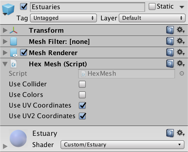
}Create a shader, material and object mouth, duplicating the coast and changing it. Connect it to the fragment and make it use the UV and UV2 coordinates.
Estuarties object.
Estuary triangulation
We can solve the problem of a hole or overlay by placing a triangle between the end of the river and the middle edge of the water. Since our mouth shader is a duplicate of the coast shader, let's set the UV coordinates that match the foam effect.
voidTriangulateEstuary (EdgeVertices e1, EdgeVertices e2) {
…
estuaries.AddTriangle(e1.v3, e2.v2, e2.v4);
estuaries.AddTriangleUV(
new Vector2(0f, 0f), new Vector2(0f, 1f), new Vector2(0f, 1f)
);
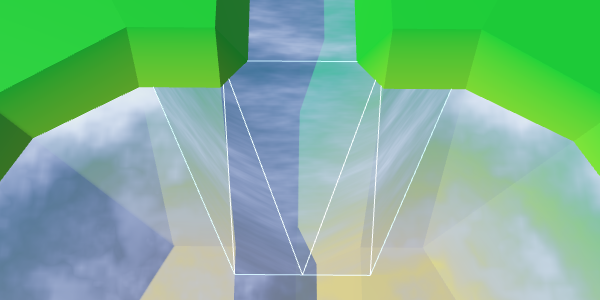
}Middle triangle.
We can fill the entire trapezoid by adding a quad on both sides of the middle triangle.
		estuaries.AddQuad(e1.v2, e1.v3, e2.v1, e2.v2);
		estuaries.AddTriangle(e1.v3, e2.v2, e2.v4);
		estuaries.AddQuad(e1.v3, e1.v4, e2.v4, e2.v5);
		estuaries.AddQuadUV(0f, 0f, 0f, 1f);
		estuaries.AddTriangleUV(
			new Vector2(0f, 0f), new Vector2(0f, 1f), new Vector2(0f, 1f)
		);
		estuaries.AddQuadUV(0f, 0f, 0f, 1f);
Ready trapezoid.
Let's turn the orientation of the quad to the left so that it has a shortened diagonal connection, and as a result we get a symmetric geometry.
		estuaries.AddQuad(e2.v1, e1.v2, e2.v2, e1.v3);
		estuaries.AddTriangle(e1.v3, e2.v2, e2.v4);
		estuaries.AddQuad(e1.v3, e1.v4, e2.v4, e2.v5);
		estuaries.AddQuadUV(
			new Vector2(0f, 1f), new Vector2(0f, 0f),
			new Vector2(0f, 1f), new Vector2(0f, 0f)
		);
//		estuaries.AddQuadUV(0f, 0f, 0f, 1f);
Rotated quad, symmetric geometry
River flow
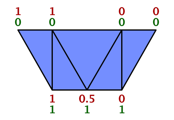
To support the effect of the river, we need to add UV2 coordinates. The bottom of the middle triangle is in the middle of the river, so its U coordinate should be equal to 0.5. As the river flows towards the water, the left point receives the U coordinate equal to 1, and the right one - the U coordinate with the value 0. Let the Y coordinates be 0 and 1, corresponding to the direction of flow.
		estuaries.AddTriangleUV2(
			new Vector2(0.5f, 1f), new Vector2(1f, 0f), new Vector2(0f, 0f)
		);
The quadrilaterals on both sides of the triangle must coincide with this orientation. We keep the same U coordinates for points that exceed the width of the river.
		estuaries.AddQuadUV2(
			new Vector2(1f, 0f), new Vector2(1f, 1f),
			new Vector2(1f, 0f), new Vector2(0.5f, 1f)
		);
		estuaries.AddTriangleUV2(
			new Vector2(0.5f, 1f), new Vector2(1f, 0f), new Vector2(0f, 0f)
		);
		estuaries.AddQuadUV2(
			new Vector2(0.5f, 1f), new Vector2(0f, 1f),
			new Vector2(0f, 0f), new Vector2(0f, 0f)
		);
UV2 trapezoid.
To make sure that we set the UV2 coordinates correctly, let the Estuary shader render them. We can access these coordinates by adding to the input structure
float2 uv2_MainTex. struct Input {
float2 uv_MainTex;
float2 uv2_MainTex;
float3 worldPos;
};
…
void surf (InputIN, inout SurfaceOutputStandard o) {
float shore = IN.uv_MainTex.y;
float foam = Foam(shore, IN.worldPos.xz, _MainTex);
float waves = Waves(IN.worldPos.xz, _MainTex);
waves *= 1 - shore;
fixed4 c = fixed4(IN.uv2_MainTex, 1, 1);
…
}UV2 coordinates.
Everything looks good, you can use a shader to create a river effect.
void surf (InputIN, inout SurfaceOutputStandard o) {
			…
			float river = River(IN.uv2_MainTex, _MainTex);
			fixed4 c = saturate(_Color + river);
			…
		}
Use UV2 to create a river effect.
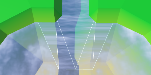
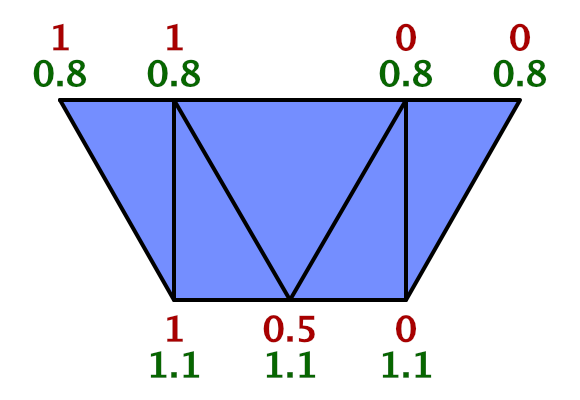
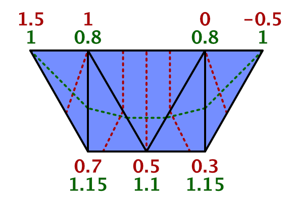
We created rivers in such a way that when triangulating the connections between the cells, the V coordinates of the river change from 0.8 to 1. Therefore, here we should also use this interval, and not values from 0 to 1. However, the coast connection is 50% larger than normal cell connections . Therefore, for best fit with the course of the river, we must change the values from 0.8 to 1.1.
estuaries.AddQuadUV2(
new Vector2(1f, 0.8f), new Vector2(1f, 1.1f),
new Vector2(1f, 0.8f), new Vector2(0.5f, 1.1f)
);
estuaries.AddTriangleUV2(
new Vector2(0.5f, 1.1f),
new Vector2(1f, 0.8f),
new Vector2(0f, 0.8f)
);
estuaries.AddQuadUV2(
new Vector2(0.5f, 1.1f), new Vector2(0f, 1.1f),
new Vector2(0f, 0.8f), new Vector2(0f, 0.8f)
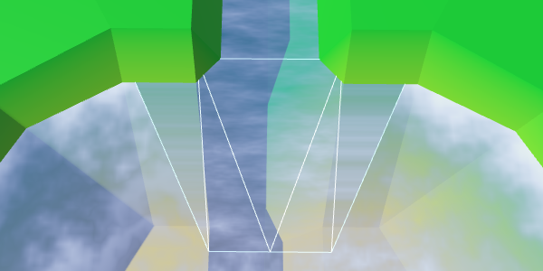
);Synchronized flow of the river and the mouth.
Flow control
While the current of the river moves in a straight line. But when water flows into a larger area, it expands. The flow will be bent. We can simulate this by folding the UV2 coordinates.
Instead of keeping the upper coordinates U constant beyond the width of the river, let's shift them by 0.5. The leftmost point is set to 1.5, the rightmost one is −0.5.
At the same time, we will expand the flow by shifting the coordinates U of the left and right points of the bottom. Change the left one from 1 to 0.7, and the right one from 0 to 0.3.
		estuaries.AddQuadUV2(
			new Vector2(1.5f, 0.8f), new Vector2(0.7f, 1.1f),
			new Vector2(1f, 0.8f), new Vector2(0.5f, 1.1f)
		);
		…
		estuaries.AddQuadUV2(
			new Vector2(0.5f, 1.1f), new Vector2(0.3f, 1.1f),
			new Vector2(0f, 0.8f), new Vector2(-0.5f, 0.8f)
		);
The expansion of the flow of the river.
To complete the curvature effect, change the V coordinates of the same four points. As the water flows away from the end of the river, we will increase the V coordinates of the upper points to 1. And in order to create a better curve, we will increase the V coordinates of the two lower points to 1.15.
		estuaries.AddQuadUV2(
			new Vector2(1.5f, 1f), new Vector2(0.7f, 1.15f),
			new Vector2(1f, 0.8f), new Vector2(0.5f, 1.1f)
		);
		estuaries.AddTriangleUV2(
			new Vector2(0.5f, 1.1f),
			new Vector2(1f, 0.8f),
			new Vector2(0f, 0.8f)
		);
		estuaries.AddQuadUV2(
			new Vector2(0.5f, 1.1f), new Vector2(0.3f, 1.15f),
			new Vector2(0f, 0.8f), new Vector2(-0.5f, 1f)
		);
Curved river flow.
Mixing river and coast
All we have left is to mix the effects of the coast and the river. To do this, we use linear interpolation, taking the value of the coast as an interpolator.
			float shoreWater = max(foam, waves);
			float river = River(IN.uv2_MainTex, _MainTex);
			float water = lerp(shoreWater, river, IN.uv_MainTex.x);
			fixed4 c = saturate(_Color + water);
Although this should work, you may get a compilation error. The compiler complains about overriding
_MainTex_ST. The reason is an error inside the Unity surface shader compiler caused by using uv_MainTexand simultaneously uv2_MainTex. We need to find a workaround. Instead of using,
uv2_MainTexwe’ll have to transfer the secondary UV coordinates manually. To do this, rename uv2_MainTexto riverUV. Then we add a vertex function to the shader, which assigns coordinates to it. #pragma surface surf Standard alpha vertex:vert
…
struct Input {
float2 uv_MainTex;
float2 riverUV;
float3 worldPos;
};
…
void vert (inout appdata_full v, outInput o) {
UNITY_INITIALIZE_OUTPUT(Input, o);
o.riverUV = v.texcoord1.xy;
}
void surf (InputIN, inout SurfaceOutputStandard o) {
…
float river = River(IN.riverUV, _MainTex);
…
}Interpolation based on the value of the coast.
Interpolation works, except for the left and right vertex at the top. At these points, the river should disappear. Therefore, we can not use the value of the coast. We have to use a different value, which in these two vertices is 0. Fortunately, we still have the U coordinate of the first set of UVs, so we can store this value there.
		estuaries.AddQuadUV(
			new Vector2(0f, 1f), new Vector2(0f, 0f),
			new Vector2(1f, 1f), new Vector2(0f, 0f)
		);
		estuaries.AddTriangleUV(
			new Vector2(0f, 0f), new Vector2(1f, 1f), new Vector2(1f, 1f)
		);
		estuaries.AddQuadUV(
			new Vector2(0f, 0f), new Vector2(0f, 0f),
			new Vector2(1f, 1f), new Vector2(0f, 1f)
		);
//		estuaries.AddQuadUV(0f, 0f, 0f, 1f);
Proper mixing.
Now the mouths have a good mix between the expanding river, the coastal water and the foam. Although it does not create an exact match with waterfalls, this effect looks good with waterfalls.
Mouth in action
unitypackage
Rivers flowing from reservoirs
We already have rivers flowing into reservoirs, but there is no support for rivers flowing in a different direction. There are lakes from which rivers flow, so we need to add them too.
When a river flows out of a reservoir, it actually flows towards a greater height. This is currently not possible. We need to make an exception and allow this situation if the water level corresponds to the height of the target point. Let's add to the
HexCellprivate method, checking by our new criterion, whether the neighbor is the correct target point for the outgoing river.boolIsValidRiverDestination (HexCell neighbor) {
return neighbor && (
elevation >= neighbor.elevation || waterLevel == neighbor.elevation
);
}We will use our new method to determine whether it is possible to create an outgoing river.
publicvoidSetOutgoingRiver (HexDirection direction) {
		if (hasOutgoingRiver && outgoingRiver == direction) {
			return;
		}
		HexCell neighbor = GetNeighbor(direction);
//		if (!neighbor || elevation < neighbor.elevation) {if (!IsValidRiverDestination(neighbor)) {
			return;
		}
		RemoveOutgoingRiver();
		…
	}
Also there you need to check the river when the height of the cell or water level changes. Create a private method that will take care of this task.
voidValidateRivers () {
		if (
			hasOutgoingRiver &&
			!IsValidRiverDestination(GetNeighbor(outgoingRiver))
		) {
			RemoveOutgoingRiver();
		}
		if (
			hasIncomingRiver &&
			!GetNeighbor(incomingRiver).IsValidRiverDestination(this)
		) {
			RemoveIncomingRiver();
		}
	}
We use this new method in the properties
Elevationand WaterLevel.publicint Elevation {
…
set {
…
// if (// hasOutgoingRiver &&// elevation < GetNeighbor(outgoingRiver).elevation// ) {// RemoveOutgoingRiver();// }// if (// hasIncomingRiver &&// elevation > GetNeighbor(incomingRiver).elevation// ) {// RemoveIncomingRiver();// }
ValidateRivers();
…
}
}
publicint WaterLevel {
…
set {
if (waterLevel == value) {
return;
}
waterLevel = value;
ValidateRivers();
Refresh();
}
}Outgoing and entering the lakes of the river.
Unfolding flow
We created
HexGridChunk.TriangulateEstuary, assuming that rivers can only flow into reservoirs. Therefore, as a result, the flow of a river always moves in one direction. We need to reverse the flow when dealing with a river flowing from a reservoir. For this you need to TriangulateEstuaryknow about the direction of flow. Therefore, we will give it a boolean parameter that determines whether we are dealing with an incoming river.voidTriangulateEstuary (
EdgeVertices e1, EdgeVertices e2, bool incomingRiver
) {
…
}We will transmit this information when calling this method from
TriangulateWaterShore.if (cell.HasRiverThroughEdge(direction)) {
TriangulateEstuary(e1, e2, cell.IncomingRiver == direction);
}Now we need to turn the flow of the river, changing the coordinates of UV2. The coordinates of U for outgoing rivers need to be mirrored: −0.5 becomes 1.5, 0 becomes 1, 1 becomes 0, and 1.5 becomes −0.5.
With V coordinates, things are a little more complicated. If you look at how we worked with inverted connections of rivers, then 0.8 should be 0, and 1 should be −0.2. This means that 1.1 becomes −0.3, and 1.15 becomes −0.35.
Since in each case the coordinates of UV2 are very different, let's write a separate code for them.
voidTriangulateEstuary (
		EdgeVertices e1, EdgeVertices e2, bool incomingRiver
	) {
		…
		if (incomingRiver) {
			estuaries.AddQuadUV2(
				new Vector2(1.5f, 1f), new Vector2(0.7f, 1.15f),
				new Vector2(1f, 0.8f), new Vector2(0.5f, 1.1f)
			);
			estuaries.AddTriangleUV2(
				new Vector2(0.5f, 1.1f),
				new Vector2(1f, 0.8f),
				new Vector2(0f, 0.8f)
			);
			estuaries.AddQuadUV2(
				new Vector2(0.5f, 1.1f), new Vector2(0.3f, 1.15f),
				new Vector2(0f, 0.8f), new Vector2(-0.5f, 1f)
			);
		}
		else {
			estuaries.AddQuadUV2(
				new Vector2(-0.5f, -0.2f), new Vector2(0.3f, -0.35f),
				new Vector2(0f, 0f), new Vector2(0.5f, -0.3f)
			);
			estuaries.AddTriangleUV2(
				new Vector2(0.5f, -0.3f),
				new Vector2(0f, 0f),
				new Vector2(1f, 0f)
			);
			estuaries.AddQuadUV2(
				new Vector2(0.5f, -0.3f), new Vector2(0.7f, -0.35f),
				new Vector2(1f, 0f), new Vector2(1.5f, -0.2f)
			);
		}
	}
The correct flow of the rivers.
unitypackage
Part 9: relief objects
- Add objects to the relief.
- Create support for density levels of objects.
- We use various objects in the level.
- We mix three different types of objects.
In this part we will talk about adding objects to the relief. We will create objects such as buildings and trees.
Conflict between forests, agricultural land and urbanization.
Add support for objects
Although the shape of the relief has variations, while nothing happens on it. It is a lifeless land. To breathe life into it, you need to add such objects. like trees and houses. These objects are not part of the relief mesh, but will be separate objects. But this will not prevent us from adding them when triangulating the terrain.
HexGridChunkdon't care how the mesh works. He simply orders one of his children to HexMeshadd a triangle or quad. Likewise, it can have a child element that places objects on them.Object Manager
Let's create a component
HexFeatureManagerthat will deal with objects within one fragment. We use the same scheme as in HexMesh- we give it methods Clear, Applyand AddFeature. Since the object needs to be placed somewhere, the method AddFeaturereceives the position parameter. We will start with the implementation-procurement, which so far will not do anything.
using UnityEngine;
publicclassHexFeatureManager : MonoBehaviour {
	publicvoidClear () {}
	publicvoidApply () {}
	publicvoidAddFeature (Vector3 position) {}
}
Now we can add a link to such a component in
HexGridChunk. Then you can include it in the process of triangulation, as well as all child elements HexMesh.public HexFeatureManager features;
publicvoidTriangulate () {
terrain.Clear();
rivers.Clear();
roads.Clear();
water.Clear();
waterShore.Clear();
estuaries.Clear();
features.Clear();
for (int i = 0; i < cells.Length; i++) {
Triangulate(cells[i]);
}
terrain.Apply();
rivers.Apply();
roads.Apply();
water.Apply();
waterShore.Apply();
estuaries.Apply();
features.Apply();
}Let's start by placing one object in the center of each cell.
voidTriangulate (HexCell cell) {
		for (HexDirection d = HexDirection.NE; d <= HexDirection.NW; d++) {
			Triangulate(d, cell);
		}
		features.AddFeature(cell.Position);
	}
Now we need a real object manager. Add another child to the Hex Grid Chunk prefab and give it a component
HexFeatureManager. Then you can connect a fragment with it.Object manager added to fragment prefab.
Prefab objects
What terrain object will we create? For the first test, the cube is quite suitable. Create a sufficiently large cube, for example, with a scale (3, 3, 3), and turn it into a prefab. Also create a material for it. I used the default material with red color. Remove it from the collider, because we do not need it.
Prefab Cube.
Object managers will need a link to this prefab, so add it to
HexFeatureManager, and then connect them. Since placing an object requires access to the transform component, we use it as a reference type.public Transform featurePrefab;Object manager with prefab.
Creating instances of objects
The structure is ready, and we can begin to add relief objects! Simply create an instance of the prefab in
HexFeatureManager.AddFeatureand set its position.publicvoidAddFeature (Vector3 position) {
Transform instance = Instantiate(featurePrefab);
instance.localPosition = position;
}Instances of relief objects.
From this point on, the relief will be filled with cubes. At the very least, the upper halves of the cubes, because the local origin point for the cube mesh in Unity is in the center of the cube, and the lower part is below the surface of the relief. To place the cubes on topography, we need to move them up half their height.
publicvoidAddFeature (Vector3 position) {
		Transform instance = Instantiate(featurePrefab);
		position.y += instance.localScale.y * 0.5f;
		instance.localPosition = position;
	}
Cubes on the surface of the relief.
What if we use another mesh?
Такой подход применим только для стандартного куба. Если мы используем собственные меши, то лучше будет создавать их так, чтобы их локальная точка начала координат находилась внизу. Тогда не придётся вообще изменять их позицию.
Of course, our cells are distorted, so we need to distort the position of objects. So we get rid of the perfect repeatability of the grid.
instance.localPosition = HexMetrics.Perturb(position);Distorted positions of objects.
Destruction of relief objects
With each update of the fragment, we create new relief objects. This means that while we are creating more and more objects in the same positions. To avoid duplicates, we need to get rid of old objects when cleaning up a fragment.
The fastest way to do this is by creating a container game object and turning all the relief objects into its children. Then, when
Clearwe call, we will destroy this container and create a new one. The container itself will be a child of its manager. Transform container;
publicvoidClear () {
if (container) {
Destroy(container.gameObject);
}
container = new GameObject("Features Container").transform;
container.SetParent(transform, false);
}
…
publicvoidAddFeature (Vector3 position) {
Transform instance = Instantiate(featurePrefab);
position.y += instance.localScale.y * 0.5f;
instance.localPosition = HexMetrics.Perturb(position);
instance.SetParent(container, false);
}Probably inefficient every time to create and destroy objects of relief.
Да, кажется, что это так. Но пока нас это волновать не должно. Сначала нам нужно правильно разместить объекты. Разобравшись с этим, мы увидим, что такие действия являются узким местом, поэтому подумаем об эффективности. Именно тогда мы можем прийти и к использованию метода
HexFeatureManager.Apply. Но оставим это для будущего туториала. К счастью, всё не так плохо, потому что мы разделили рельеф на фрагменты.unitypackage
Placement of objects of relief
For now, we place objects in the center of each cell. For empty cells, this looks normal, but on cells containing rivers and roads, as well as flooded with water, it seems strange.
Objects are located everywhere.
Therefore, before placing the object, let's check in
HexGridChunk.Triangulatewhether the cell is empty.if (!cell.IsUnderwater && !cell.HasRiver && !cell.HasRoads) {
features.AddFeature(cell.Position);
}Limited accommodation.
One object per direction
Only one object per cell is not too much. There is plenty of room for heaps of objects. Therefore, we add an additional object to the center of each of the six triangles of the cell, that is, one per direction.
We will do this in another method
Triangulatewhen we know that there is no river in the cell. We still need to check whether we are under water and whether there is a road in the cell. But in this case, we are only interested in the roads going in the current direction.voidTriangulate (HexDirection direction, HexCell cell) {
…
if (cell.HasRiver) {
…
}
else {
TriangulateWithoutRiver(direction, cell, center, e);
if (!cell.IsUnderwater && !cell.HasRoadThroughEdge(direction)) {
features.AddFeature((center + e.v1 + e.v5) * (1f / 3f));
}
}
…
}Many facilities, but not in the vicinity of the rivers.
This creates many more objects! They appear alongside the roads, but they still avoid the rivers. To place objects along the rivers, we can also add them inside
TriangulateAdjacentToRiver. But again only when the triangle is not under water and there is no road on it.voidTriangulateAdjacentToRiver (
HexDirection direction, HexCell cell, Vector3 center, EdgeVertices e
) {
…
if (!cell.IsUnderwater && !cell.HasRoadThroughEdge(direction)) {
features.AddFeature((center + e.v1 + e.v5) * (1f / 3f));
}
}Objects appeared alongside the rivers.
Is it possible to render so many objects?
Большое количество объектов создаёт множество вызовов отрисовки, но здесь помогает dynamic batching движка Unity. Так как объекты малы, их меши должны иметь всего несколько вершин. Это позволяет объединить многие из них в один batch. Но если это окажется «узким местом», то придётся поработать с ними в будущем. Также можно использовать instancing, который при работе со множеством мелких мешей сравним с dynamic batching.
unitypackage
Variety of objects
All our relief objects have the same orientation, which looks completely unnatural. Let's give each of them a random turn.
publicvoidAddFeature (Vector3 position) {
		Transform instance = Instantiate(featurePrefab);
		position.y += instance.localScale.y * 0.5f;
		instance.localPosition = HexMetrics.Perturb(position);
		instance.localRotation = Quaternion.Euler(0f, 360f * Random.value, 0f);
		instance.SetParent(container, false);
	}
Random turns.
So the result becomes much more diverse. Unfortunately, each time a fragment is updated, objects get a new random rotation. Editing cells should not change the objects in the neighborhood, so we need a different approach.
We have a noise texture that is always the same. However, this texture contains Perlin's gradient noise, and it is locally matched. This is what we need when we distort the positions of the vertices in the cells. But the turns do not have to be coordinated. All turns should be equally probable and mixed. Therefore, we need a texture with non-gradient random values that can be sampled without bilinear filtering. In essence, this is a hash grid that creates the basis of gradient noise.
Creating a hash table
We can create a hash table from an array of float values and fill it once with random values. Thanks to this, we don’t need a texture at all. Let's add it to
HexMetrics. A size of 256 by 256 is enough for sufficient variability.publicconstint hashGridSize = 256;
staticfloat[] hashGrid;
publicstaticvoidInitializeHashGrid () {
hashGrid = newfloat[hashGridSize * hashGridSize];
for (int i = 0; i < hashGrid.Length; i++) {
hashGrid[i] = Random.value;
}
}Random values are generated by a mathematical formula that always gives the same results. The resulting sequence depends on the number of seed, which by default is equal to the current time value. That is why in each game session we will receive different results.
To ensure the re-creation of always identical objects, we need to add the seed parameter to the initialization method.
publicstaticvoidInitializeHashGrid (int seed) {
		hashGrid = newfloat[hashGridSize * hashGridSize];
		Random.InitState(seed);
		for (int i = 0; i < hashGrid.Length; i++) {
			hashGrid[i] = Random.value;
		}
	}
Now that we have initialized the random number stream, we will always get the same sequence from it. Therefore, seemingly random events occurring after the card generation will also always be the same. We can avoid this by maintaining the state of the random number generator before it is initialized. After completing the work, we can ask him the old state.
		Random.State currentState = Random.state;
		Random.InitState(seed);
		for (int i = 0; i < hashGrid.Length; i++) {
			hashGrid[i] = Random.value;
		}
		Random.state = currentState;
The hashes table is initialized
HexGridat the same time that it assigns a noise texture. That is, in the methods HexGrid.Startand HexGrid.Awake. Let's make it so that values are generated no more often than necessary.publicint seed;
voidAwake () {
HexMetrics.noiseSource = noiseSource;
HexMetrics.InitializeHashGrid(seed);
…
}
voidOnEnable () {
if (!HexMetrics.noiseSource) {
HexMetrics.noiseSource = noiseSource;
HexMetrics.InitializeHashGrid(seed);
}
}The common seed variable allows us to choose the seed value for the card. Any value will do. I chose 1234.
Selection of seed.
Using the hash table
To use the hash table, add to the
HexMetricssampling method. Like it SampleNoise, it uses the xz position to get the value. The hash index is found by limiting the coordinates to integer values, and then obtaining the remainder of the integer division by the size of the table.publicstaticfloatSampleHashGrid (Vector3 position) {
int x = (int)position.x % hashGridSize;
int z = (int)position.z % hashGridSize;
return hashGrid[x + z * hashGridSize];
}What is he doing %?
Это оператор модуля, он вычисляет остаток от деления, в нашем случае — целочисленного деления. Например, ряд −4, −3, −2, −1, 0, 1, 2, 3, 4 modulo 3 превращается в −1, 0, −2, −1, 0, 1, 2, 0, 1.
This works for positive coordinates, but not for negative ones, because for such numbers the remainder will be negative. We can fix this by adding a table size to negative results.
int x = (int)position.x % hashGridSize;
		if (x < 0) {
			x += hashGridSize;
		}
		int z = (int)position.z % hashGridSize;
		if (z < 0) {
			z += hashGridSize;
		}
Now for each square unit we create our own value. However, in reality, we do not need such a density table. Objects are separated from each other further. We can stretch the table by reducing the scale of the position before calculating the index. We will need only one unique value for a 4 by 4 square.
publicconstfloat hashGridScale = 0.25f;
	publicstaticfloatSampleHashGrid (Vector3 position) {
		int x = (int)(position.x * hashGridScale) % hashGridSize;
		if (x < 0) {
			x += hashGridSize;
		}
		int z = (int)(position.z * hashGridScale) % hashGridSize;
		if (z < 0) {
			z += hashGridSize;
		}
		return hashGrid[x + z * hashGridSize];
	}
Let's go back to
HexFeatureManager.AddFeatureand use our new hash table to get the value. After we apply it to set the rotation, the objects while editing the relief will remain fixed.publicvoidAddFeature (Vector3 position) {
float hash = HexMetrics.SampleHashGrid(position);
Transform instance = Instantiate(featurePrefab);
position.y += instance.localScale.y * 0.5f;
instance.localPosition = HexMetrics.Perturb(position);
instance.localRotation = Quaternion.Euler(0f, 360f * hash, 0f);
instance.SetParent(container, false);
}Accommodation threshold
Although objects have a different turn, the pattern is still noticeable in their placement. There are seven objects in each cell. We can add chaos to this scheme by arbitrarily omitting some of the objects. How do we decide whether to add an object or not? Of course, testing another random value!
That is, now instead of a single hash value, we need two. Their support can be added by using a hash table instead of a
floatvariable as the array type Vector2. But vector operations do not make sense for hash values, so let's create a special structure for this purpose. She will need only two float values. And let's add a static method to create a pair of randomized values.using UnityEngine;
publicstruct HexHash {
publicfloat a, b;
publicstatic HexHash Create () {
HexHash hash;
hash.a = Random.value;
hash.b = Random.value;
return hash;
}
}Shouldn't it be serialized?
Мы храним эти структуры только в таблице хешей, которая статична, поэтому при рекомпиляции не будет сериализоваться движком Unity. Следовательно, она не обязана быть сериализуемой.
Change it
HexMetricsso that it uses the new structure.static HexHash[] hashGrid;
publicstaticvoidInitializeHashGrid (int seed) {
hashGrid = new HexHash[hashGridSize * hashGridSize];
Random.State currentState = Random.state;
Random.InitState(seed);
for (int i = 0; i < hashGrid.Length; i++) {
hashGrid[i] = HexHash.Create();
}
Random.state = currentState;
}
publicstatic HexHash SampleHashGrid (Vector3 position) {
…
}Now
HexFeatureManager.AddFeaturehas access to two hash values. Let's use the first to decide whether to add an object, or skip it. If the value is equal to or greater than 0.5, then we skip it. In this case, we get rid of about half of the objects. The second value will normally be used to determine the turn.publicvoidAddFeature (Vector3 position) {
HexHash hash = HexMetrics.SampleHashGrid(position);
if (hash.a >= 0.5f) {
return;
}
Transform instance = Instantiate(featurePrefab);
position.y += instance.localScale.y * 0.5f;
instance.localPosition = HexMetrics.Perturb(position);
instance.localRotation = Quaternion.Euler(0f, 360f * hash.b, 0f);
instance.SetParent(container, false);
}The density of objects is reduced by 50%.
unitypackage
Drawing objects
Instead of placing objects everywhere, let's make them editable. But we will not draw separate objects, but add the level of objects to each cell. This level will control the likelihood of objects in the cell. By default, the value is zero, that is, the objects will be absent.
Since red cubes do not look like natural objects on our relief, let's call them buildings. They will represent urbanization. Let's add to the
HexCelllevel of urbanization.publicint UrbanLevel {
get {
return urbanLevel;
}
set {
if (urbanLevel != value) {
urbanLevel = value;
RefreshSelfOnly();
}
}
}
int urbanLevel;We can make it so that the level of urbanization for the underwater cell is zero, but this is not necessary, we already skip the creation of underwater objects. And perhaps at some stage we will add water objects of urbanization, such as docks and underwater structures.
Density slider
To change the level of urbanization, we will add
HexMapEditorone more slider in support.int activeUrbanLevel;
…
bool applyUrbanLevel;
…
publicvoidSetApplyUrbanLevel (bool toggle) {
applyUrbanLevel = toggle;
}
publicvoidSetUrbanLevel (float level) {
activeUrbanLevel = (int)level;
}
voidEditCell (HexCell cell) {
if (cell) {
…
if (applyWaterLevel) {
cell.WaterLevel = activeWaterLevel;
}
if (applyUrbanLevel) {
cell.UrbanLevel = activeUrbanLevel;
}
if (riverMode == OptionalToggle.No) {
cell.RemoveRiver();
}
…
}
}Add another slider to the UI and connect it with the appropriate methods. I will place a new panel on the right side of the screen to avoid overflowing the left panel.
How many levels will we need? Let's look at four that denote zero, low, medium, and high density.
Urbanization slider.
Threshold change
Now that we have a level of urbanization, we need to use it to determine whether to place objects. To do this, we need to add the level of urbanization as an additional parameter in
HexFeatureManager.AddFeature. Let's take one more step and just pass the cell itself. In the future we will be more comfortable. The fastest way to take advantage of the level of urbanization is by multiplying it by 0.25 and using the value as a new threshold for skipping objects. Due to this, the probability of an object will increase with each level by 25%.
publicvoidAddFeature (HexCell cell, Vector3 position) {
		HexHash hash = HexMetrics.SampleHashGrid(position);
		if (hash.a >= cell.UrbanLevel * 0.25f) {
			return;
		}
		…
	}
To make it work, pass the cells to
HexGridChunk.voidTriangulate (HexCell cell) {
…
if (!cell.IsUnderwater && !cell.HasRiver && !cell.HasRoads) {
features.AddFeature(cell, cell.Position);
}
}
voidTriangulate (HexDirection direction, HexCell cell) {
…
if (!cell.IsUnderwater && !cell.HasRoadThroughEdge(direction)) {
features.AddFeature(cell, (center + e.v1 + e.v5) * (1f / 3f));
}
…
}
…
voidTriangulateAdjacentToRiver (
HexDirection direction, HexCell cell, Vector3 center, EdgeVertices e
) {
…
if (!cell.IsUnderwater && !cell.HasRoadThroughEdge(direction)) {
features.AddFeature(cell, (center + e.v1 + e.v5) * (1f / 3f));
}
}Drawing density levels of urbanization.
unitypackage
Several prefabs of relief objects
The differences in the probability of objects appearing are not enough to create a clear separation between low and high levels of urbanization. In some cells, there will simply be more or less than the expected number of buildings. We can make the difference clearer by using our own prefab for each level.
Let's get rid of the field
featurePrefabin HexFeatureManagerand replace it with an array for the prefabs of urbanization. To obtain the corresponding prefab, we will subtract one from the level of urbanization and use the value as an index.<del>// public Transform featurePrefab;</del>public Transform[] urbanPrefabs;
publicvoidAddFeature (HexCell cell, Vector3 position) {
…
Transform instance = Instantiate(urbanPrefabs[cell.UrbanLevel - 1]);
…
}We will create two duplicates of the prefab of the object, rename and change them so that they denote three different levels of urbanization. Level 1 is low density, so we use a cube with a unit edge length, which denotes a shack. I will scale the prefab level 2 to (1.5, 2, 1.5) to make it look like a two-story building. For tall buildings of level 3, I used the scale (2, 5, 2).
Using different prefabs for each level of urbanization.
Mixing prefabs
We are not obliged to limit ourselves to strict division of building types. You can mix them up a bit, as it happens in the real world. Instead of one threshold per level, let's use three, one for each type of building.
At level 1, we use shackling in 40% of cases. There will be no other buildings here at all. For the level we use three values (0.4, 0, 0).
At level 2, we replace the shacks with more buildings, and add a 20% probability for additional shacks. High buildings will not do. That is, we use the threshold three values (0.2, 0.4, 0).
At level 3, we replace medium buildings with high ones, replace shacks again, and add another probability of 20% shacks. The threshold values will be equal to (0.2, 0.2, 0.4).
That is, the idea is that as the level of urbanization increases, we will upgrade existing buildings and add new ones to empty places. To delete an existing building, we need to use the same hash value intervals. If the hashes between 0 and 0.4 at level 1 were shacks, then at level 3 the same spacing will create tall buildings. At level 3, tall buildings should be created with hash values in the range of 0–0.4, two-story buildings in the range of 0.4–0.6, and shacks in the range of 0.6–0.8. If you check them from highest to lowest, then this can be done with the help of triple thresholds (0.4, 0.6, 0.8). The thresholds of level 2 will then become (0, 0.4, 0.6), and the thresholds of level 1 will become (0, 0, 0.4).
Let's save these thresholds in
HexMetricsas a collection of arrays with a method that allows you to get thresholds for a certain level. Since we are only interested in levels with objects, we ignore level 0.staticfloat[][] featureThresholds = {
newfloat[] {0.0f, 0.0f, 0.4f},
newfloat[] {0.0f, 0.4f, 0.6f},
newfloat[] {0.4f, 0.6f, 0.8f}
};
publicstaticfloat[] GetFeatureThresholds (int level) {
return featureThresholds[level];
}Next, add to the
HexFeatureManagermethod that uses the level and hash value to select the prefab. If the level is greater than zero, then we get the thresholds using the level reduced by one. Then we loop through the thresholds until one of them exceeds the value of the hash. This will mean that we have found the prefab. If not found, then return null.Transform PickPrefab (int