Rzborda, or How to Make an Internet-Controlled Typewriter
Over the past few years I have been able to make many remotely controlled devices. Some were controlled locally, from a regular PC or from a smartphone. Some over the Internet. All devices are united by a common principle - a person controls them, guided by the picture from the video camera on board the device. And the control itself, in the end, comes down to issuing control signals to servomotors or regulators (drivers) of motors.
So, having gained experience in this matter, I decided to try to more or less systematize the various types of device management, so that when creating a new device I did not have to rewrite a bunch of everything, but just change some configuration parameters. As a result, the RCboard or RCboard software package was born. Because I do all managed things with the Virt2real controller (Virtualrilka ) as the main onboard brain, then the rcboard was originally written specifically for it. So the whole bunch can be pathetically called the “Software and Hardware Complex of RCboard”.
In general, in the continuation of the topic I’ll try to write a recipe about how to use the Virtualryka and RCboards from a conventional radio-controlled machine to make a machine controlled via the Internet (well, it will also be controlled locally). The communication channel will be regular Wi-Fi (access to the Internet via a home router) or 4G communication through the Yota whistle.
Crawler BSD Racing 4WD RTR 2.4Ghz 1:10

I’ll clarify right away - by the term “radio-controlled machine” I mean not cheap Chinese cars in which all the electronics are implemented on one board, but more or less decent cars built on a modular scheme - which have an engine speed regulator (collector, brushless - it doesn’t matter) and Servo for controlling the front wheels.
I will give such a machine as an experimental rabbit only in this recipe, since it is easiest to repeat. With small changes in the settings of the control boards and the addition of a handkerchief-engine speed controller, the same thing can be done with any machine, the main thing is that the machine has wheels (and at least tracks) and a motor.
But first, to demonstrate some use cases
As I already wrote, we already used a lot of boards, but from documented cases I found only these:
habrahabr.ru/company/virt2real/blog/223145
habrahabr.ru/company/virt2real/blog/223183
By the way, the snow blower himself - development of Perm guys http://omiplow.ru
Joint project with an open research center for advanced technologies
The crawler for remote control is good in that it has a very high cross.
The crawler has four-wheel drive, a constant differential lock (all wheels spin at the same time) and a constant "low gear". Those. he drives relatively slowly, but powerfully and passable.
Before assembling the machine, you need to configure the Virtualrilka. First, consider the Wi-Fi connection option.
So, on points:
Typically, RC cars have two motors. One ordinary, collector - spins the wheels. The second is a servomotor, turns the front wheels in the right direction. Those. it turns out that only two control channels are required - gas and steering wheel. Initially (if the machine is purchased assembled), all channels are connected to the standard radio with three-pin JR connectors (standard servo connector). Black (or brown) wire - ground, red - power (5-6V), yellow (or white, or orange) - signal wire.
It is through the signal wire that we will control the motors, but first we need to supply power to the servo, which drives the wheels. Here the general principle is this: from an onboard battery, power supply with a voltage equal to the voltage of the battery goes through thick wires to a powerful regulator of the collector (or brushless) motor. Inside this regulator there is a so-called BEC - a voltage converter that makes stable 5 Volts (sometimes 6V, you can choose a jumper on the regulator) from various battery voltages, which are required to power on-board servos, a receiver and various other electronics. This stabilized power supply is usually designed for a load of no more than 2-3A, although this also depends on the model of the regulator.
The output voltage of the BEC through the black and red wires of a thin three-wire loop from the regulator is supplied to the receiver. Here lies the main nuance that not everyone immediately comprehends. I repeat - there is a cable with three wires from the regulator. Of these, two cores are power, which is issued from the regulator, i.e. this is the way out. And the third wire (white, yellow or orange) is the control wire, i.e. entrance. It seems a trifle, but for some reason many are confused.
The receiver has several groups of three-pin contacts. Their number depends on the number of channels for which the receiver is designed. Typically, machines have 2 or 3 channels, so groups, respectively, 3 or 4 (one group for setting the jumper Pair (signal for pairing the receiver and transmitter). For these groups of contacts, all power pins are closed to each other, i.e., ground and power comes from the regulator and is supplied immediately to all groups of contacts, but the signal pins are all independent, they receive a signal received by the receiver from the radio control equipment.
Since we will manage using an independent controller, we don’t need the native receiver of the machine, we remove it altogether. And we need to connect the three-core loops from the controller and from the servo in a tricky way - connect the black wire to black, red to red. And the remaining white (yellow or orange) two wires must be connected to the Virtrilka, namely to the pins CON44 and CON43, see the diagram . Which wire to which pin does not really matter, since the channels can be configured later in the configuration boards.
You should get something like this.
If at hand there are servo extenders - it is convenient to make a connection with their help. I have an eternal strain with them, so I just cut the wires and twist-solder.
And yes, the most important thing is that we supply power to the Virtualrilka directly from the battery contacts. She is not afraid of voltage up to 20V, so the higher the voltage, the better, the less current will consume. The efficiency of the power converter (SEPIC, installed on the Virtrilka itself) drops only after 15V, so that the ideal power supply is from 12 to 15 V, while at the full load (with wifi) the Virtrilka will consume about 150-300 mA. Although this also depends on the whistle (the Yota whistle is very voracious, it will be more with it).
I tried to shoot a video of the build process of my crawler. I don’t know how clear everything is, but I don’t think it will be superfluous. Here is a video about the assembly:
All settings of the control boards can be edited in a special control panel of the control boards (not to be confused with the admin panel of Virtualrilki). This is how the control boards of the control boards look like now (first version)
In the General Settings tab, you can set the device name (displayed when the device is detected in applications), specify whether the control boards server should be started automatically when Virtualirki loads, and specify the configuration type.
The configuration can be local (that is, the configuration file is constantly located in the catalogs directory and can be edited in the control panel), or it can be deleted when the configuration file is downloaded each time the boards are launched from the web server.
Remote Config Server, by default, http://rc.virt2real.ru/getconfig, only registered users of the forum.virt2real.ru forum are allowed to create and edit configurations .
In the topic, I will only talk about the local configuration, you can try the remote yourself if you are interested. By the way, when I was driving on a typewriter in Shenzhen (video at the end of the topic), then I just used the remote config so that I could change the settings. Changing the settings from the application is still in the form of sketches, it really does not work yet, but even when I finish it, the remote config will still come in handy.
So, the tab “Local configuration” is of most interest to us now. In general, the default config already sets up the board in server mode, you can connect the machine and control it locally (in the local network, from the Windows application, from the android or from the iPhone-iPad). Unless you may need to swap channels. But for the P2P (peer-to-peer) mode, for controlling via the Internet, the settings will have to be changed.
By default, the universal.so library is responsible for all control, the parameters for which are at the end of the config, in the "[universal]" section.
The correspondence between the control channels and the PWM / PPM channels is set by the axis parameter.
By default, 4 PPM channels are configured, which are on the pins CON43, CON44, CON19, CON42. These lines of the config are responsible for this
The channel setting format is:
chX = CON, TYPE, MIN, CENTER, MAX, NEUTRAL, NOAUTOCENTER
Where
X is the PWM / PPM channel number, from 0 to 3
CON is the pin number (not GPIO, namely the pin, see diagram )
TYPE - signal type, ppm or pwm. For the machine you need ppm, for the pwm type a different config string format.
MIN - minimum position of the PPM signal, in milliseconds.
MAX - maximum position of the PPM signal, in milliseconds.
CENTER is the center position of the PPM signal, in milliseconds.
NEUTRAL - relative neutral value, i.e. neutral meaning of control commands. Usually = 127
NOAUTOCENTER- if = 0 - automatically return the signal to the center position, = 1 - do not return. For the gas channels and the steering wheel of the machine, you need to specify 0, for the channels of the servo drives that are used to rotate the viewing camera, you need to specify 1 (if there are such, of course)
If there are lights on the machine, you can turn them on and off, you need to assemble a simple transistor amplifier one field effect transistor, in fact). To obtain a control signal, the pins parameter is used. It sets the pins that will be set to 0 or 1 when a button is pressed in Virt2real Player (on screen buttons, on the keyboard, mouse, or on the gamepad).
The format is:
pins = CHANNEL, CON, DEFVALUE, SAVESTATE | ...
where
CHANNEL is the button channel (from 1 to 32)
CON is the pin number that you want to set to 0 or 1 upon the arrival of the control command from the
DEFVALUE buttons - value, in which this pin will be set when starting the SAVESTATE control
boards - if = 0 - set the pin to 1 when the button is pressed, set to 0 when released. If = 1 - set the pin to 1 when the button is pressed, do nothing when the button is released. The next time you press the button, set the pin to 0, and when released, do nothing again. And so in the loop.
Button channels can be specified in a row through the separator "|".
A brief conclusion from this vague information - if you have gas and steering channels mixed up - you can swap them by changing the axis parameter to axis = 1,0,2,3 :-)
If you need to limit the extreme position of the steering servo - change the MIN and MAX values for the desired channel. If the machine goes forward or backward in the neutral position, change the CENTER value for the desired channel.
In the tab "Additional Modules" is a list of active and inactive modules boards.

A module is a separate application (executable binary) that usually acts as a telemetry source. Active modules are those that start automatically at the start of the wordboards and end when it finishes. In the control panel, you can move modules from one column to another by clicking on the orange arrow. When moving to the active column - the module starts immediately, no matter if the board is running or not. When moving to inactive - the module automatically stops working.
The modules work simply - they read the required parameters and send them to the local port (ext_telemetry) specified in the config via UDP. And there already rtsborda accepts Old and transmits via telemetry channel to the application Virt2real Player. At the same time, the same information is transferred to the device’s user library (in our case, it is universal.so) so that the application can analyze the information and use it for its intended purpose. For example, I had a library of a device called autobot.so - a controlled trolley that, in addition to user control, could also drive autonomously, guided by the signal from the ultrasonic range finder.
Of the main modules - statuswifi delivers information about the status of the wifi link to the RC board. Airosstatus.php (yes, the module can also be written on the hook) - reads the status of the link from the Ubiquity equipment, gps - reads the GPS receiver. The imu module processes the information from inertial sensors (forms Euler angles, azimuth and compass), although it currently only works with one type of sensor, so it is not suitable for universal use. Nfc - reads NFC tags, but also works with only one type of reader. rc.in - reads PPM signals from an RC receiver, i.e. The machine can also be controlled from a regular app, it has priority over control commands via wifi. rfid - Read RFID tags. statusyota - reads the status of the 4G link of the Yota modem. usrange - reads the readings of ultrasonic rangefinders. voltage - determines the supply voltage of the board, A simple voltage divider (2 resistors) is required to connect to the ADC0. In general, there are a lot of interesting modules, for each there is a detailed description to do, so for now we believe that I mentioned them for seed :-)
For our recipe for a controlled machine, the statuswifi module is relevant - if we set up a connection via Wi-Fi or statusyota - if we connect Virtualka through the Yota whistle.
In Android and iPad-iPhone applications, the settings are simple, they consist only in the choice of control channels. In Android there is also a choice of the channel of the buttons (by default the channel is not set, the buttons are not displayed). But in the Windows application, I twisted so many features that I myself enter a state of light panic when I realize that I need to document all this. For now, I can only give a link to the description of the previous version of the application
http://wiki.virt2real.ru/wiki/How_to_make_managed_cart_2
http://wiki.virt2real.ru/wiki/RCboard
The control protocol has since noticeably changed, but the configuration of the Windows application has changed slightly, so it can help with picking. I’ll try to write a detailed description of the current version next year :-)
By the way, in the earliest version I used the MAVLINK protocol for transmitting telemetry, but as it became fouled with features, it became lacking, so I switched to my protocol. And I’m thinking of adding MAVLINK as a parallel telemetry channel, but this is already in the next version of the application.
I will say only one thing - it’s best to control the machine with the USB steering wheel and pedals connected to the computer. Well, or at least with an RC app connected to the computer by a coaching connector. And fingers on the screen of a smartphone can be cool, but nifiga is not convenient without tactile sensations.
Since UDP is used for the control channel and for the video channel, I wanted to make a full-fledged P2P (Peer-to-peer) link so as not to drive the video from the board to the server and back to the client. Well, if I wanted to, I took it and did it :-) Actually, it turned out to be a simple and easy analogue of the Adobe RTMFP (not to be confused with RTMP). Only here the sound transmission does not add any way, so the rzborda is still dumb and deaf.
With UDP, what is the main problem - NAT bridging. Since at one end of the link (on the transmitting side or on the receiving side) there is necessarily NAT - just specify the address and port of the server (or client) will not work - NAT will interfere. In the Windows Virt2real Player it is possible to use UPnP to forward the port, but this is not exactly what I wanted. And what I wanted - it turned out only after thoughtful technology smokingUDP Hole Punching . In the end, everything turned out as it should - no matter which router, no matter where the client or server is. The main thing is to have access to the Internet. Although I am lying, there is one single type of NAT that has not yet been able to penetrate. All the time I forget how it is correctly called, seemingly symmetric NAT.
And yes, the usual TURN and STUN servers are not used in the board, only their own implementation. As I usually say: if you want to learn technology, do it your own way, and then compare it with generally accepted solutions. Bike lovers will understand me. However, it often turns out that the bike is not so bad and performs its tasks better than generally accepted decisions.
This is so, there was an easy offtopic. We continue about NAT. Support for P2P is so far only in the Windows application Virt2real Player, has not yet been added to the Android and iPhone-iPad. I checked the work with the connection through the Yota whistle, through the Beeline 4G whistle, through the access point on the smartphone, which also went to the Internet through Beeline 4G. In all these cases, everything works, but noticed that it is ideal only through Yota. Through the beeline (in any of the tested types) it also works, but the connection takes longer. Why this happens - until I figured it out. From the sad - so far it has not been possible to get the link to work (both commands and video) when both the client and server are connected via 4G whistles. Perhaps here just symmetric NAT also crept up.
A Wi-Fi whistle is connected to the Virtualrilka on board the machine (i.e., as they did so far according to the instructions from this topic). Only at first we controlled the machine locally, and now we can let someone steer from the Internet.
To enable p2p mode, go to the control panel web boards, section "Local settings". There we set the parameter
Now you need to set the parameters p2p_uid and p2p_hash. This is a kind of login-password analogue, but there is no full-fledged authorization yet (but it will be necessary), so we use just such a bunch. p2p_uid is better to take from your account on rc.virt2real.ru/remoteconfig there it is called "User ID", then the invite mechanism will work (more on that below). And p2p_hash needs to be invented independently. Any character set, maximum length 40 characters.
That's all, the setup of p2p rzborda mode is over. You need to make sure that Virtualrilka has access to the Internet and that you can run Virt2real Player Windows. If you run it on a local network, in the same place as the board, the player will detect the local board (it does not matter that it is in p2p mode) and you can connect directly. But if the player runs on another network, you need to configure it in p2p mode.
We right-click on the player’s window, go to the “Network” menu -> “Network Settings”. In the "Role" tab, select "P2P", in the "P2P" tab, specify the UID and DevID. UID is the same p2p_uid that the boards entered in the settings, and DevID is that p2p_hash. Save, again right-click on the video window, “Network” -> “Connect”. In the lower left corner of the player should appear the message "Request peer video" and "Request peer commands." That's it, the process of detecting the feast and pairing has begun.
Sometimes it happens that messages do not appear, then it’s better to simply restart the player (my jamb, I haven’t caught it yet), when it starts, it will immediately begin to connect with the parameters that we set for it, i.e. in P2P mode.
From the noted nuances - if the player is launched on a computer that goes online through Yota - the connection is quickly installed. Of course, if Iota has a normal signal. But if through a Yota router or 4G a whistle from Beeline - the first connection can last up to a minute. But then all subsequent ones will be almost instantly. I roughly know where I screwed up, but fix until my hands reached.
We connect the Yota whistle (via the USB-OTG adapter, of course) to the micro-USB port of Virtualrilka on board the machine. Those whistles that are now on sale at Yota
Otherwise, everything is similar to the previous paragraph. It’s good to remove the statuswifi module from active scripts in the settings section in the “Additional modules” section and vice versa, put the statusyota module in active scripts in order to see the Yota signal parameters in the player.
Unfortunately, at home, Yota barely furs, so you can’t fully ride. But Beeline 4G works fine, the 3 megabit stream (both incoming and outgoing) prolazit without problems.
In all the experiments below, all settings are the same, only the type of connection changes.
To make it easier to transfer parameters to someone to connect to our typewriter in P2P mode, some suggestions for the invite mechanism were created. What are invites - everyone knows. Convenient thing. So now I’ll try to tell you how to use it. In the player it is still in a test, raw, form, but it seems to work.
So, open the Windows Virt2real Player, right-click on the window, select “Invite” -> “Create invite”. An important nuance - the player must be configured for P2P mode, i.e. In the network settings, all the above parameters for connecting to the machine are indicated. Otherwise, an invite will be created, but there will be nothing to connect to. By the way, it would be necessary to add a warning if the parameters are not filled.
In the field "Your user ID" we enter all the same our p2p_uid.
In the field “Your user-magic” we enter the contents of the field “Your user-magic” from the same page rc.virt2real.ru/remoteconfig
In the field “Name of invite” we enter the name under which this invite will be on the page rc.virt2real.ru / remoteconfig is displayed.
Now click on the “Create invite” button. The tweak-logo should spin, after which a long line will appear in the lower field “Line-invite”, starting with the characters INV.
Now, if you open the remote configuration page rc.virt2real.ru/remoteconfig, we see that there appeared an invite that we just created

Well, then just drop this line to those who want to give a ride. And he, in turn, should go to the menu "Invite" in the player -> "I have an invite!" and enter this line. After that, all the necessary parameters will be filled by themselves, you won’t have to configure anything to connect, you can immediately ride.
As I said, the system is damp, but it works. The plans are to make normal authorization by login-password, so that you do not have to bother with usermagic and other identifiers.
The main requirement for remote control is one - the smallest possible delay from pressing a button or moving the joystick to the corresponding change in the image displayed on board the device in the video stream. When you publish something about remote control, the first question is usually “what is the delay?”.
After numerous tests, it turned out that delays are a subjective thing and affect the comfort of control in different ways. Of course, it all depends on the maximum speed of the driving device. For flying devices (airplanes / copters), the minimum delay is very important, but when controlling driving devices - not always. When I cut through the hall at the next Hobby-Expo exhibition on a converted radio-controlled buggy, after ten minutes of taxiing I caught myself thinking that the delay (whatever it may be) ceases to be felt, you start to control “in advance”. At almost half the speed (and my buggy can accelerate to 80 km / h) he calmly drove around the hall, maneuvering between pavilions, chairs, people. So here, rather, the stability of the delay is more important than its absolute value in milliseconds. The minimum delay achieved when connecting to a regular router via a regular Wi-Fi whistle was somewhere around 200 ms, and when connecting through a generally recognized standard, powerful Ubiquity routers had a minimum delay of about 100 ms with a confident connection. The delay is also affected by the power of the video stream playback device (PC, smartphone), if it does not have time to decode the raw video stream (H264 codec) then there will be no pleasant smooth video.
When I ran a rather high-speed buggy in Shenzhen, sitting at home in Moscow, it was quite comfortable to steer, although only the network ping from me to the server of the Chinese 4G operator was about 300 ms. Plus, another 100 ms of ours - total runs in half a second. However, a great ride :-)
After wild drops when flying on an airplane, we figured out what the problem was. If the connection is via 4G, you must set the mtu parameter to 1322 or less. Less is not necessary, we set mtu = 1322 and do not worry. On a local network, I usually set 16,000 (the maximum size of Jumbo Frames), in LAN it works fine, but over the Internet there will already be problems with the passage of packets.
Since the text turned out to be over-than-dofiga, I’ll repeat the main links.
Firmware rcboard-0.01.002.zip for Virtrilka
Virt2real Player distribution kit for Windows .
The same thing, but not the installer, but just an archive
Under Win8, it incorrectly checks for DirectX, so you can simply unzip the archive. Requires .Net 4.5 and DirectX.
Description of the previous version of RCboards and Virt2real Player
Another description of RCboards, old protocol
Android application . Only local management.
IOS app , only local management, no device detection. Now there is the old version, the new one is undergoing an app.
PS Ehh, sorry Bond Wheelbarrow did not live up to the appearance of the board :-(
So, having gained experience in this matter, I decided to try to more or less systematize the various types of device management, so that when creating a new device I did not have to rewrite a bunch of everything, but just change some configuration parameters. As a result, the RCboard or RCboard software package was born. Because I do all managed things with the Virt2real controller (Virtualrilka ) as the main onboard brain, then the rcboard was originally written specifically for it. So the whole bunch can be pathetically called the “Software and Hardware Complex of RCboard”.
In general, in the continuation of the topic I’ll try to write a recipe about how to use the Virtualryka and RCboards from a conventional radio-controlled machine to make a machine controlled via the Internet (well, it will also be controlled locally). The communication channel will be regular Wi-Fi (access to the Internet via a home router) or 4G communication through the Yota whistle.
Crawler BSD Racing 4WD RTR 2.4Ghz 1:10
I’ll clarify right away - by the term “radio-controlled machine” I mean not cheap Chinese cars in which all the electronics are implemented on one board, but more or less decent cars built on a modular scheme - which have an engine speed regulator (collector, brushless - it doesn’t matter) and Servo for controlling the front wheels.
I will give such a machine as an experimental rabbit only in this recipe, since it is easiest to repeat. With small changes in the settings of the control boards and the addition of a handkerchief-engine speed controller, the same thing can be done with any machine, the main thing is that the machine has wheels (and at least tracks) and a motor.
What will be needed for assembly
- Machine with engine control, engine and servo
- Battery (any with suitable voltage for the regulator)
- Virt2real controller (Virtualrilka) with a camera, USB-OTG adapter, micro-SD flash drive
- Wi-Fi or Yota whistle (you can use any other 4G modem)
- Hands of moderate linearity
But first, to demonstrate some use cases
Where has it been used
As I already wrote, we already used a lot of boards, but from documented cases I found only these:
Shenzhen test rcboards for buggies, control from Moscow
Tests rtsbordy on the crawler in St. Petersburg, management from Moscow
habrahabr.ru/company/virt2real/blog/223145
Tests rtsbordy on an airplane over St. Petersburg, control from Moscow
habrahabr.ru/company/virt2real/blog/223183
Cool snowboard driven by snowboards
By the way, the snow blower himself - development of Perm guys http://omiplow.ru
The heaviest device running rzbordy
Joint project with an open research center for advanced technologies
So, the experimental rabbit
The crawler for remote control is good in that it has a very high cross.
By the way, he even knows how to do like this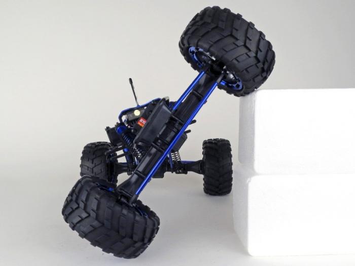
The crawler has four-wheel drive, a constant differential lock (all wheels spin at the same time) and a constant "low gear". Those. he drives relatively slowly, but powerfully and passable.
Configuring Virtualrilki
Before assembling the machine, you need to configure the Virtualrilka. First, consider the Wi-Fi connection option.
So, on points:
- Download the latest firmware, especially for filesboard.virt2real.ru/firmware/virt2real-board/1.1/rcboard-0.01.002.zip
- We connect micro-USB - USB cable to Virtrilka, we stick the other end into the computer. A new network interface will appear on the computer, the 192.168.3.0/24 subnet. For Windows, you may need to install a driver.
- We open the basic admin panel (web-panel for managing the Virtualka) at the address http://192.168.3.1/admin
- We go to the "Settings" -> "Network" section and set the ip for the wlan0 interface (or specify dhcp if you do not need a static ip)
- We go to the "Settings" -> "Wi-Fi" -> "Wi-Fi Settings" section and set the wireless network parameters (change the ssid and psk fields) for the first network
- We go to the "Settings" -> "Autostart" section - move the S80dhcp-server script to inactive (if the initial configuration via USB is no longer required)
- We go to the section "Administration" -> "Reboot" and rebuild the Virtualka
- We disconnect the USB cable from the Virtualrilka, connect the whistle to the micro-USB wifi. Of the recommended ones, I recommend ASUS N10, N13, TP-link TL-WM722N, but it is best five-gigahertz, for example ASUS N53 or Dlink DWA-160 rev.B2
Checking the connection of Virtualrilka to the network
- In the process of loading Virtrilki, the LEDs on it will light up. When you turn on the power, if the bootable USB flash drive is successfully read, the green LED will light up. Then, in the process of loading the kernel, the blue LED will light up. After a full download, if the connection to the Wi-Fi network is successful, the red LED will light up. And when the control board starts (it is registered in the autorun), all the LEDs go out, the red LED starts blinking).
- Install the management application. It is called Virt2real Player and is for Windows ( distribution or zip archive ), for Android , for IOS . The IOS application in the appstore is still of the old version, the new one passes the apprut, so for now if you put it to no purpose - the management will work clumsily.
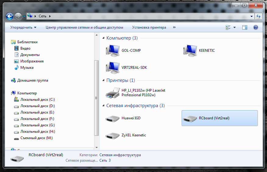
- Open Explorer (if on a Windows computer), if Virtualrilka successfully connects to the local network via Wi-Fi - in the Network section, the RCboard (Virt2real) device should appear. You can get to the admin panel by right-clicking on this device and selecting the menu item “View device web page”It looks something like this
- We launch Virt2real Player for Windows or for Android, the RCboard server should be detected. Server discovery in an iOS application has not yet been implemented.Screenshot Virt2real Player for Windows
 Screenshot Virt2real Player for Android
The general principle of connecting the motors of the machine
Typically, RC cars have two motors. One ordinary, collector - spins the wheels. The second is a servomotor, turns the front wheels in the right direction. Those. it turns out that only two control channels are required - gas and steering wheel. Initially (if the machine is purchased assembled), all channels are connected to the standard radio with three-pin JR connectors (standard servo connector). Black (or brown) wire - ground, red - power (5-6V), yellow (or white, or orange) - signal wire.
It is through the signal wire that we will control the motors, but first we need to supply power to the servo, which drives the wheels. Here the general principle is this: from an onboard battery, power supply with a voltage equal to the voltage of the battery goes through thick wires to a powerful regulator of the collector (or brushless) motor. Inside this regulator there is a so-called BEC - a voltage converter that makes stable 5 Volts (sometimes 6V, you can choose a jumper on the regulator) from various battery voltages, which are required to power on-board servos, a receiver and various other electronics. This stabilized power supply is usually designed for a load of no more than 2-3A, although this also depends on the model of the regulator.
The output voltage of the BEC through the black and red wires of a thin three-wire loop from the regulator is supplied to the receiver. Here lies the main nuance that not everyone immediately comprehends. I repeat - there is a cable with three wires from the regulator. Of these, two cores are power, which is issued from the regulator, i.e. this is the way out. And the third wire (white, yellow or orange) is the control wire, i.e. entrance. It seems a trifle, but for some reason many are confused.
The receiver has several groups of three-pin contacts. Their number depends on the number of channels for which the receiver is designed. Typically, machines have 2 or 3 channels, so groups, respectively, 3 or 4 (one group for setting the jumper Pair (signal for pairing the receiver and transmitter). For these groups of contacts, all power pins are closed to each other, i.e., ground and power comes from the regulator and is supplied immediately to all groups of contacts, but the signal pins are all independent, they receive a signal received by the receiver from the radio control equipment.
Common wiring diagram with a collector motor
Conventional brushless motor connection diagram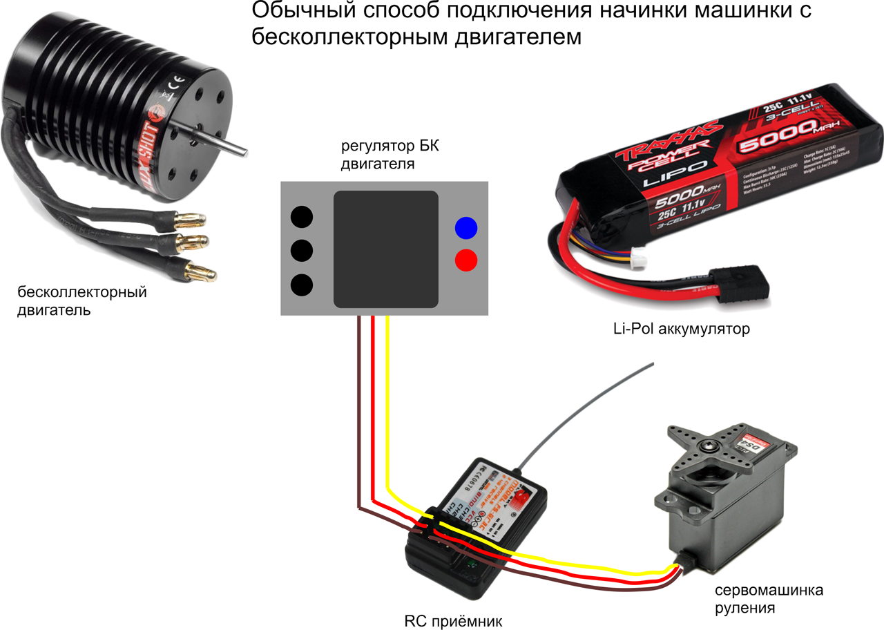
Since we will manage using an independent controller, we don’t need the native receiver of the machine, we remove it altogether. And we need to connect the three-core loops from the controller and from the servo in a tricky way - connect the black wire to black, red to red. And the remaining white (yellow or orange) two wires must be connected to the Virtrilka, namely to the pins CON44 and CON43, see the diagram . Which wire to which pin does not really matter, since the channels can be configured later in the configuration boards.
You should get something like this.
Scheme of connecting Virtualrilka to the intestines of the machine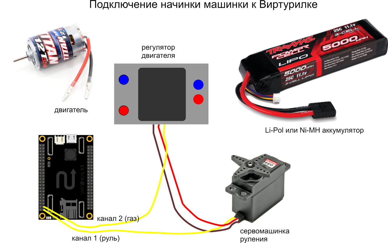
If at hand there are servo extenders - it is convenient to make a connection with their help. I have an eternal strain with them, so I just cut the wires and twist-solder.
And yes, the most important thing is that we supply power to the Virtualrilka directly from the battery contacts. She is not afraid of voltage up to 20V, so the higher the voltage, the better, the less current will consume. The efficiency of the power converter (SEPIC, installed on the Virtrilka itself) drops only after 15V, so that the ideal power supply is from 12 to 15 V, while at the full load (with wifi) the Virtrilka will consume about 150-300 mA. Although this also depends on the whistle (the Yota whistle is very voracious, it will be more with it).
Machine assembly
I tried to shoot a video of the build process of my crawler. I don’t know how clear everything is, but I don’t think it will be superfluous. Here is a video about the assembly:
Configuring a server
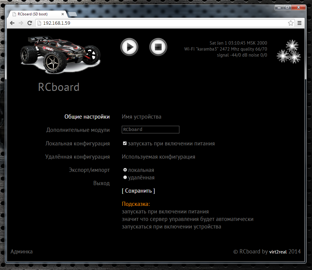
All settings of the control boards can be edited in a special control panel of the control boards (not to be confused with the admin panel of Virtualrilki). This is how the control boards of the control boards look like now (first version)
In the General Settings tab, you can set the device name (displayed when the device is detected in applications), specify whether the control boards server should be started automatically when Virtualirki loads, and specify the configuration type.
The configuration can be local (that is, the configuration file is constantly located in the catalogs directory and can be edited in the control panel), or it can be deleted when the configuration file is downloaded each time the boards are launched from the web server.
Remote Config Server, by default, http://rc.virt2real.ru/getconfig, only registered users of the forum.virt2real.ru forum are allowed to create and edit configurations .
In the topic, I will only talk about the local configuration, you can try the remote yourself if you are interested. By the way, when I was driving on a typewriter in Shenzhen (video at the end of the topic), then I just used the remote config so that I could change the settings. Changing the settings from the application is still in the form of sketches, it really does not work yet, but even when I finish it, the remote config will still come in handy.
So, the tab “Local configuration” is of most interest to us now. In general, the default config already sets up the board in server mode, you can connect the machine and control it locally (in the local network, from the Windows application, from the android or from the iPhone-iPad). Unless you may need to swap channels. But for the P2P (peer-to-peer) mode, for controlling via the Internet, the settings will have to be changed.
By default, the universal.so library is responsible for all control, the parameters for which are at the end of the config, in the "[universal]" section.
The correspondence between the control channels and the PWM / PPM channels is set by the axis parameter.
axis = 0,1,2,3
By default, 4 PPM channels are configured, which are on the pins CON43, CON44, CON19, CON42. These lines of the config are responsible for this
ch0 = 43, ppm, 500,1500,2500,127,0
ch1 = 44, ppm, 500,1500,2500,127,0 ch2
= 19, ppm, 500,1500,2500,127,1
ch3 = 42, ppm , 500,1500,2500,127,1
The channel setting format is:
chX = CON, TYPE, MIN, CENTER, MAX, NEUTRAL, NOAUTOCENTER
Where
X is the PWM / PPM channel number, from 0 to 3
CON is the pin number (not GPIO, namely the pin, see diagram )
TYPE - signal type, ppm or pwm. For the machine you need ppm, for the pwm type a different config string format.
MIN - minimum position of the PPM signal, in milliseconds.
MAX - maximum position of the PPM signal, in milliseconds.
CENTER is the center position of the PPM signal, in milliseconds.
NEUTRAL - relative neutral value, i.e. neutral meaning of control commands. Usually = 127
NOAUTOCENTER- if = 0 - automatically return the signal to the center position, = 1 - do not return. For the gas channels and the steering wheel of the machine, you need to specify 0, for the channels of the servo drives that are used to rotate the viewing camera, you need to specify 1 (if there are such, of course)
If there are lights on the machine, you can turn them on and off, you need to assemble a simple transistor amplifier one field effect transistor, in fact). To obtain a control signal, the pins parameter is used. It sets the pins that will be set to 0 or 1 when a button is pressed in Virt2real Player (on screen buttons, on the keyboard, mouse, or on the gamepad).
pins = 1.30.0.0 | 2.31.0.1
The format is:
pins = CHANNEL, CON, DEFVALUE, SAVESTATE | ...
where
CHANNEL is the button channel (from 1 to 32)
CON is the pin number that you want to set to 0 or 1 upon the arrival of the control command from the
DEFVALUE buttons - value, in which this pin will be set when starting the SAVESTATE control
boards - if = 0 - set the pin to 1 when the button is pressed, set to 0 when released. If = 1 - set the pin to 1 when the button is pressed, do nothing when the button is released. The next time you press the button, set the pin to 0, and when released, do nothing again. And so in the loop.
Button channels can be specified in a row through the separator "|".
A brief conclusion from this vague information - if you have gas and steering channels mixed up - you can swap them by changing the axis parameter to axis = 1,0,2,3 :-)
If you need to limit the extreme position of the steering servo - change the MIN and MAX values for the desired channel. If the machine goes forward or backward in the neutral position, change the CENTER value for the desired channel.
Additional modules
In the tab "Additional Modules" is a list of active and inactive modules boards.
A module is a separate application (executable binary) that usually acts as a telemetry source. Active modules are those that start automatically at the start of the wordboards and end when it finishes. In the control panel, you can move modules from one column to another by clicking on the orange arrow. When moving to the active column - the module starts immediately, no matter if the board is running or not. When moving to inactive - the module automatically stops working.
The modules work simply - they read the required parameters and send them to the local port (ext_telemetry) specified in the config via UDP. And there already rtsborda accepts Old and transmits via telemetry channel to the application Virt2real Player. At the same time, the same information is transferred to the device’s user library (in our case, it is universal.so) so that the application can analyze the information and use it for its intended purpose. For example, I had a library of a device called autobot.so - a controlled trolley that, in addition to user control, could also drive autonomously, guided by the signal from the ultrasonic range finder.
Of the main modules - statuswifi delivers information about the status of the wifi link to the RC board. Airosstatus.php (yes, the module can also be written on the hook) - reads the status of the link from the Ubiquity equipment, gps - reads the GPS receiver. The imu module processes the information from inertial sensors (forms Euler angles, azimuth and compass), although it currently only works with one type of sensor, so it is not suitable for universal use. Nfc - reads NFC tags, but also works with only one type of reader. rc.in - reads PPM signals from an RC receiver, i.e. The machine can also be controlled from a regular app, it has priority over control commands via wifi. rfid - Read RFID tags. statusyota - reads the status of the 4G link of the Yota modem. usrange - reads the readings of ultrasonic rangefinders. voltage - determines the supply voltage of the board, A simple voltage divider (2 resistors) is required to connect to the ADC0. In general, there are a lot of interesting modules, for each there is a detailed description to do, so for now we believe that I mentioned them for seed :-)
For our recipe for a controlled machine, the statuswifi module is relevant - if we set up a connection via Wi-Fi or statusyota - if we connect Virtualka through the Yota whistle.
Application Settings
In Android and iPad-iPhone applications, the settings are simple, they consist only in the choice of control channels. In Android there is also a choice of the channel of the buttons (by default the channel is not set, the buttons are not displayed). But in the Windows application, I twisted so many features that I myself enter a state of light panic when I realize that I need to document all this. For now, I can only give a link to the description of the previous version of the application
http://wiki.virt2real.ru/wiki/How_to_make_managed_cart_2
http://wiki.virt2real.ru/wiki/RCboard
The control protocol has since noticeably changed, but the configuration of the Windows application has changed slightly, so it can help with picking. I’ll try to write a detailed description of the current version next year :-)
By the way, in the earliest version I used the MAVLINK protocol for transmitting telemetry, but as it became fouled with features, it became lacking, so I switched to my protocol. And I’m thinking of adding MAVLINK as a parallel telemetry channel, but this is already in the next version of the application.
I will say only one thing - it’s best to control the machine with the USB steering wheel and pedals connected to the computer. Well, or at least with an RC app connected to the computer by a coaching connector. And fingers on the screen of a smartphone can be cool, but nifiga is not convenient without tactile sensations.
And now the most important thing is Internet governance
Introductory information about P2P mode
Since UDP is used for the control channel and for the video channel, I wanted to make a full-fledged P2P (Peer-to-peer) link so as not to drive the video from the board to the server and back to the client. Well, if I wanted to, I took it and did it :-) Actually, it turned out to be a simple and easy analogue of the Adobe RTMFP (not to be confused with RTMP). Only here the sound transmission does not add any way, so the rzborda is still dumb and deaf.
With UDP, what is the main problem - NAT bridging. Since at one end of the link (on the transmitting side or on the receiving side) there is necessarily NAT - just specify the address and port of the server (or client) will not work - NAT will interfere. In the Windows Virt2real Player it is possible to use UPnP to forward the port, but this is not exactly what I wanted. And what I wanted - it turned out only after thoughtful technology smokingUDP Hole Punching . In the end, everything turned out as it should - no matter which router, no matter where the client or server is. The main thing is to have access to the Internet. Although I am lying, there is one single type of NAT that has not yet been able to penetrate. All the time I forget how it is correctly called, seemingly symmetric NAT.
And yes, the usual TURN and STUN servers are not used in the board, only their own implementation. As I usually say: if you want to learn technology, do it your own way, and then compare it with generally accepted solutions. Bike lovers will understand me. However, it often turns out that the bike is not so bad and performs its tasks better than generally accepted decisions.
This is so, there was an easy offtopic. We continue about NAT. Support for P2P is so far only in the Windows application Virt2real Player, has not yet been added to the Android and iPhone-iPad. I checked the work with the connection through the Yota whistle, through the Beeline 4G whistle, through the access point on the smartphone, which also went to the Internet through Beeline 4G. In all these cases, everything works, but noticed that it is ideal only through Yota. Through the beeline (in any of the tested types) it also works, but the connection takes longer. Why this happens - until I figured it out. From the sad - so far it has not been possible to get the link to work (both commands and video) when both the client and server are connected via 4G whistles. Perhaps here just symmetric NAT also crept up.
Setting up P2P mode, Wi-Fi is on board
A Wi-Fi whistle is connected to the Virtualrilka on board the machine (i.e., as they did so far according to the instructions from this topic). Only at first we controlled the machine locally, and now we can let someone steer from the Internet.
To enable p2p mode, go to the control panel web boards, section "Local settings". There we set the parameter
role = p2p
Now you need to set the parameters p2p_uid and p2p_hash. This is a kind of login-password analogue, but there is no full-fledged authorization yet (but it will be necessary), so we use just such a bunch. p2p_uid is better to take from your account on rc.virt2real.ru/remoteconfig there it is called "User ID", then the invite mechanism will work (more on that below). And p2p_hash needs to be invented independently. Any character set, maximum length 40 characters.
That's all, the setup of p2p rzborda mode is over. You need to make sure that Virtualrilka has access to the Internet and that you can run Virt2real Player Windows. If you run it on a local network, in the same place as the board, the player will detect the local board (it does not matter that it is in p2p mode) and you can connect directly. But if the player runs on another network, you need to configure it in p2p mode.
We right-click on the player’s window, go to the “Network” menu -> “Network Settings”. In the "Role" tab, select "P2P", in the "P2P" tab, specify the UID and DevID. UID is the same p2p_uid that the boards entered in the settings, and DevID is that p2p_hash. Save, again right-click on the video window, “Network” -> “Connect”. In the lower left corner of the player should appear the message "Request peer video" and "Request peer commands." That's it, the process of detecting the feast and pairing has begun.
Sometimes it happens that messages do not appear, then it’s better to simply restart the player (my jamb, I haven’t caught it yet), when it starts, it will immediately begin to connect with the parameters that we set for it, i.e. in P2P mode.
From the noted nuances - if the player is launched on a computer that goes online through Yota - the connection is quickly installed. Of course, if Iota has a normal signal. But if through a Yota router or 4G a whistle from Beeline - the first connection can last up to a minute. But then all subsequent ones will be almost instantly. I roughly know where I screwed up, but fix until my hands reached.
Setting up P2P mode, Yota is on board
We connect the Yota whistle (via the USB-OTG adapter, of course) to the micro-USB port of Virtualrilka on board the machine. Those whistles that are now on sale at Yota
Otherwise, everything is similar to the previous paragraph. It’s good to remove the statuswifi module from active scripts in the settings section in the “Additional modules” section and vice versa, put the statusyota module in active scripts in order to see the Yota signal parameters in the player.
Illustrations of various types of connection
Unfortunately, at home, Yota barely furs, so you can’t fully ride. But Beeline 4G works fine, the 3 megabit stream (both incoming and outgoing) prolazit without problems.
In all the experiments below, all settings are the same, only the type of connection changes.
Wi-Fi whistler crawler, Internet connection, via Yota
Краулер со свистком Yota, подключение из домашней локальной сети. Сигнал Yota очень плохой :-(
Краулер со свистком Wi-Fi, с ноутбука который имеет выход в инет через смартфон (Билайн 4G)
Инвайты
To make it easier to transfer parameters to someone to connect to our typewriter in P2P mode, some suggestions for the invite mechanism were created. What are invites - everyone knows. Convenient thing. So now I’ll try to tell you how to use it. In the player it is still in a test, raw, form, but it seems to work.
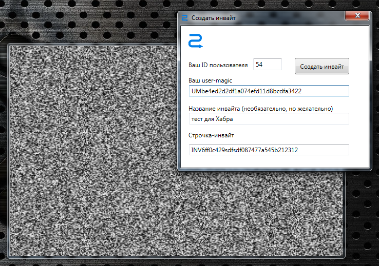
So, open the Windows Virt2real Player, right-click on the window, select “Invite” -> “Create invite”. An important nuance - the player must be configured for P2P mode, i.e. In the network settings, all the above parameters for connecting to the machine are indicated. Otherwise, an invite will be created, but there will be nothing to connect to. By the way, it would be necessary to add a warning if the parameters are not filled.
In the field "Your user ID" we enter all the same our p2p_uid.
In the field “Your user-magic” we enter the contents of the field “Your user-magic” from the same page rc.virt2real.ru/remoteconfig
In the field “Name of invite” we enter the name under which this invite will be on the page rc.virt2real.ru / remoteconfig is displayed.
Now click on the “Create invite” button. The tweak-logo should spin, after which a long line will appear in the lower field “Line-invite”, starting with the characters INV.
Now, if you open the remote configuration page rc.virt2real.ru/remoteconfig, we see that there appeared an invite that we just created
Well, then just drop this line to those who want to give a ride. And he, in turn, should go to the menu "Invite" in the player -> "I have an invite!" and enter this line. After that, all the necessary parameters will be filled by themselves, you won’t have to configure anything to connect, you can immediately ride.
As I said, the system is damp, but it works. The plans are to make normal authorization by login-password, so that you do not have to bother with usermagic and other identifiers.
A bit about the delay
The main requirement for remote control is one - the smallest possible delay from pressing a button or moving the joystick to the corresponding change in the image displayed on board the device in the video stream. When you publish something about remote control, the first question is usually “what is the delay?”.
After numerous tests, it turned out that delays are a subjective thing and affect the comfort of control in different ways. Of course, it all depends on the maximum speed of the driving device. For flying devices (airplanes / copters), the minimum delay is very important, but when controlling driving devices - not always. When I cut through the hall at the next Hobby-Expo exhibition on a converted radio-controlled buggy, after ten minutes of taxiing I caught myself thinking that the delay (whatever it may be) ceases to be felt, you start to control “in advance”. At almost half the speed (and my buggy can accelerate to 80 km / h) he calmly drove around the hall, maneuvering between pavilions, chairs, people. So here, rather, the stability of the delay is more important than its absolute value in milliseconds. The minimum delay achieved when connecting to a regular router via a regular Wi-Fi whistle was somewhere around 200 ms, and when connecting through a generally recognized standard, powerful Ubiquity routers had a minimum delay of about 100 ms with a confident connection. The delay is also affected by the power of the video stream playback device (PC, smartphone), if it does not have time to decode the raw video stream (H264 codec) then there will be no pleasant smooth video.
When I ran a rather high-speed buggy in Shenzhen, sitting at home in Moscow, it was quite comfortable to steer, although only the network ping from me to the server of the Chinese 4G operator was about 300 ms. Plus, another 100 ms of ours - total runs in half a second. However, a great ride :-)
Some nuances in 4G communication
After wild drops when flying on an airplane, we figured out what the problem was. If the connection is via 4G, you must set the mtu parameter to 1322 or less. Less is not necessary, we set mtu = 1322 and do not worry. On a local network, I usually set 16,000 (the maximum size of Jumbo Frames), in LAN it works fine, but over the Internet there will already be problems with the passage of packets.
References
Since the text turned out to be over-than-dofiga, I’ll repeat the main links.
Firmware rcboard-0.01.002.zip for Virtrilka
Virt2real Player distribution kit for Windows .
The same thing, but not the installer, but just an archive
Under Win8, it incorrectly checks for DirectX, so you can simply unzip the archive. Requires .Net 4.5 and DirectX.
Description of the previous version of RCboards and Virt2real Player
Another description of RCboards, old protocol
Android application . Only local management.
IOS app , only local management, no device detection. Now there is the old version, the new one is undergoing an app.
PS Ehh, sorry Bond Wheelbarrow did not live up to the appearance of the board :-(
If someone does not know
habrahabr.ru/company/virt2real/blog/172167
The last test when a movie came from Discovery
Now she looks like this.
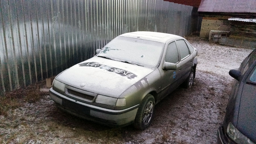
The reverse gear died, the bottom rusted and fell out. In general, kirdyk sweetie :-(
The last test when a movie came from Discovery
Now she looks like this.
The reverse gear died, the bottom rusted and fell out. In general, kirdyk sweetie :-(