IR Remote Controlled Relays on ATtiny13A
Hello, Habr!
There was a need to turn off the old, but quite working speaker system from the TV remote control without getting up from the couch. After thinking, I decided to use an IR receiver, once unscrewed from an old TV. The IR receiver was without identification marks. Having determined the outputs by the poke method, I found out that he was from the TSOP4xxx series, according to the picture:

Googling and training on the Arduino UNO using this codeand making sure the sensor was working, I switched to rewriting the code on ATtiny13. Turning to it, I realized that it is very limited in resources, both in flash and in RAM. At first, I had difficulty optimizing the size of the firmware, the controller still did not work, and when I realized that the code used in the code was much more than 64 bytes, I had to take up the optimization. As a result, with grief, I optimized the code in half and put together a prototype on the breadboard. Rejoiced like a child! It blinked as I needed.
General form:
Scheme:
It's time to translate the entire breadboard into textolite. The board was manufactured by the LUT method. The first pancake, as they say, is lumpy. Having made the first diagram, printed and assembled, I realized that nothing was working. I connected the LM317T incorrectly. In addition, having broken the nickels and torn off some too thin tracks, I decided to make a second board. In it, I made 0.7mm tracks and, increasing the nickels, somehow managed to cope with some of the problems. Here, too, it was not without problems, as it again incorrectly connected the LM317T, and even in the previous version of the board, it burned the receiver by supplying 12V to it.
By the way, this business is powered by 12V (I had a low-power transformer, so I used it). The choice of voltage was also due to the presence of a 12V relay. To reduce the voltage for the microcontroller to 5V, the LM317T stabilizer is used, and to control the relay, the KT819 transistor npn at hand is used.
Final Board at SprintLayout:
Parts used:
As for the code.
The original version was very “weighty” and could not work on ATtiny13 either. It was necessary to get rid of a heavy two-dimensional array. The code was very strange: “low” pulses were also recorded, but they were not used in any way. In general, he threw a two-dimensional array and thereby freed at least 64 bytes of RAM. I calculated the signals on the fly, but this was not enough, and after adding the timer functionality, I had to cut the variables as much as possible.
Video demo:
I was flashing ATtiny13 using Arduino UNO, using it as a programmer, guided by the publication “Flashing and programming ATtiny13 using Arduino” . For firmware used 9.6 MHz configuration.
I almost did not take photos, but what is there, that is:
Sources and firmware on Yandex disk .
myrobot.ru/wiki/index.php?n=Components.TSOP All About IR-receiver «TSOP»
www.atmel.com/images/doc2535.pdf Datasheet for the ATtiny13
habrahabr.ru/post/234477 Instructions flashing the ATtiny13
payalo. at.ua/c_fuse/calc.html?part=ATtiny13A fusion calculator for ATtiny13
github.com/nathanchantrell/TinyPCRemote/tree/master/TinyPCRemote_CodeReader , the code for reading the remote control codes that I took as a basis.
// UPD: Updated schemas. Replaced the capacitor on the relay with a diode.
There was a need to turn off the old, but quite working speaker system from the TV remote control without getting up from the couch. After thinking, I decided to use an IR receiver, once unscrewed from an old TV. The IR receiver was without identification marks. Having determined the outputs by the poke method, I found out that he was from the TSOP4xxx series, according to the picture:
Googling and training on the Arduino UNO using this codeand making sure the sensor was working, I switched to rewriting the code on ATtiny13. Turning to it, I realized that it is very limited in resources, both in flash and in RAM. At first, I had difficulty optimizing the size of the firmware, the controller still did not work, and when I realized that the code used in the code was much more than 64 bytes, I had to take up the optimization. As a result, with grief, I optimized the code in half and put together a prototype on the breadboard. Rejoiced like a child! It blinked as I needed.
General form:
Breadboard model
Scheme:
Spoiler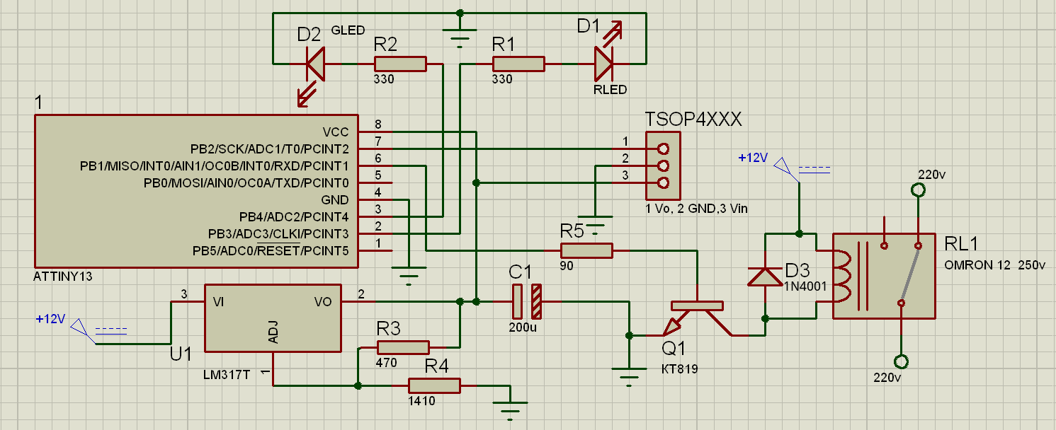
It's time to translate the entire breadboard into textolite. The board was manufactured by the LUT method. The first pancake, as they say, is lumpy. Having made the first diagram, printed and assembled, I realized that nothing was working. I connected the LM317T incorrectly. In addition, having broken the nickels and torn off some too thin tracks, I decided to make a second board. In it, I made 0.7mm tracks and, increasing the nickels, somehow managed to cope with some of the problems. Here, too, it was not without problems, as it again incorrectly connected the LM317T, and even in the previous version of the board, it burned the receiver by supplying 12V to it.
By the way, this business is powered by 12V (I had a low-power transformer, so I used it). The choice of voltage was also due to the presence of a 12V relay. To reduce the voltage for the microcontroller to 5V, the LM317T stabilizer is used, and to control the relay, the KT819 transistor npn at hand is used.
Final Board at SprintLayout:
Spoiler
Parts used:
- Microcontroller ATtiny13A;
- Resistors of 470, 1300, 2x330 and 90 Ohms;
- Transistor KT819;
- Stabilizer LM317T;
- 2 LEDs red and green;
- TSOP4XXX series receiver or compatible;
- Capacitor approximately 200-220uF;
- Diode 1N4001 or equivalent.
As for the code.
The original version was very “weighty” and could not work on ATtiny13 either. It was necessary to get rid of a heavy two-dimensional array. The code was very strange: “low” pulses were also recorded, but they were not used in any way. In general, he threw a two-dimensional array and thereby freed at least 64 bytes of RAM. I calculated the signals on the fly, but this was not enough, and after adding the timer functionality, I had to cut the variables as much as possible.
Code for Arduino IDE
#define IRpin_PIN PINB
#define IRpin 2
#define rLedPin 3
#define gLedPin 4
#define relayPin 1
#define MAXPULSE 5000
#define NUMPULSES 32
#define RESOLUTION 2
#define timeN1 1800000
#define timeN2 3600000
#define timerInterval 500
bool relayState = false;
unsigned long timer = 0;
unsigned long shift = timeN1;//30 min timer by default
unsigned long previousMillis = 0;
bool timerN = false;
byte i = 0;
void setup() {
  //default states
  DDRB |= (1<= timerInterval || previousMillis > time ) {
    previousMillis =time;
    timer1();
  }
}
unsigned long  listenForIR() {// IR receive code
  byte currentpulse = 0; // index for pulses we're storing
  unsigned long irCode = 0; // Wait for an IR Code
  irCode = irCode << 1;
  while (true) {
    unsigned int pulse = 0;// temporary storage timing
    //bool true (HIGH)
    while (IRpin_PIN & _BV(IRpin)) { // got a high pulse (99% standby time have HIGH)
      if(++i > 150){//check timer every 150 iterations (high frequency break ir code timing)
        i = 0;
        checkTimer();
      }
      pulse++;
      delayMicroseconds(RESOLUTION);
      if (((pulse >= MAXPULSE) && (currentpulse != 0)) || currentpulse == NUMPULSES ) {
        return irCode;
      }
    }
	//make irCode
    irCode = irCode << 1;
    if ((pulse * RESOLUTION) > 0 && (pulse * RESOLUTION) < 500) {
      irCode |= 0;
    }else {
      irCode |= 1;
    }
    currentpulse++;
	pulse = 0;
        //bool false (LOW)
    while (!(IRpin_PIN & _BV(IRpin))) {//wait before new pulse
      //checkTimer();
      pulse++;
      delayMicroseconds(RESOLUTION);
      if (pulse >= MAXPULSE || currentpulse == NUMPULSES ) {
        //Serial.println(irCode);
        return irCode;
      }
    }
  }//end while(1)
}//end listenForIR
//executing every timerInverval
void timer1() {
  if(timer != 0){
    if(timerN == true){//timeN1 or timeN2
      PORTB |= (1< millis())){
    timer = 0;
    shutDown();
  }
}
Video demo:
I was flashing ATtiny13 using Arduino UNO, using it as a programmer, guided by the publication “Flashing and programming ATtiny13 using Arduino” . For firmware used 9.6 MHz configuration.
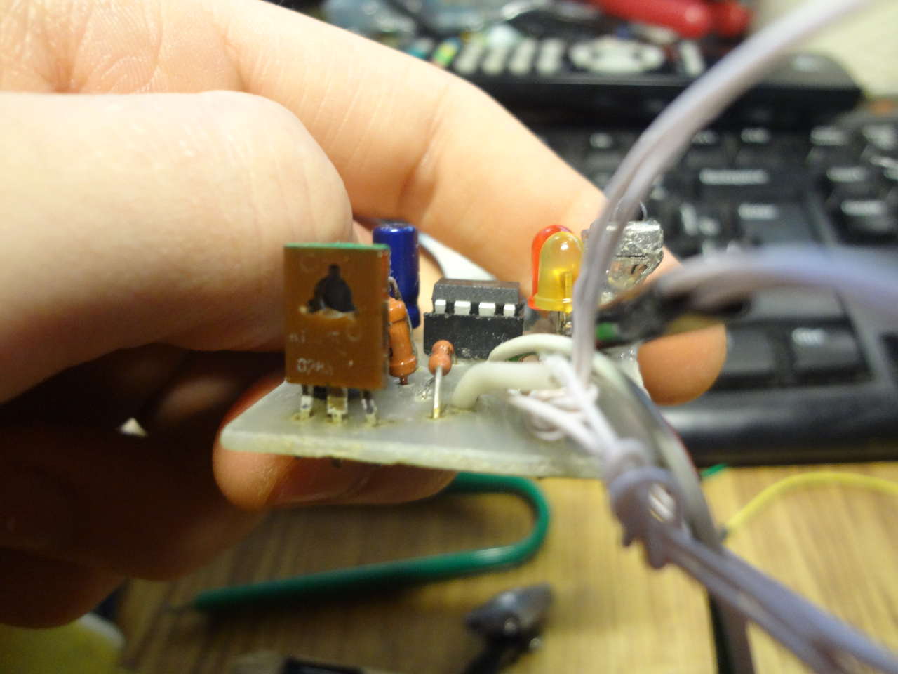
I almost did not take photos, but what is there, that is:
A photo
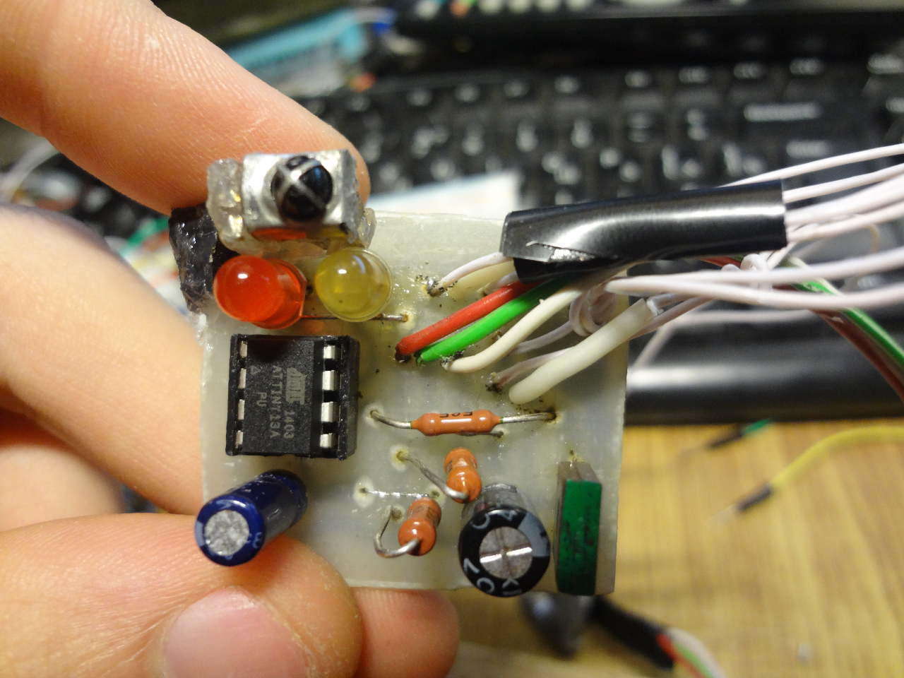
Due to another pinout of the spare TSOP in the second version, I had to transfer it to the wiring and fix it with glue (later I just attached it to the case).
Second board on the side:
Second board on top (IR sensor transferred):
Second board on the bottom:

End device:

Second board on the side:
Second board on top (IR sensor transferred):
Second board on the bottom:
End device:
Sources and firmware on Yandex disk .
Materials used
myrobot.ru/wiki/index.php?n=Components.TSOP All About IR-receiver «TSOP»
www.atmel.com/images/doc2535.pdf Datasheet for the ATtiny13
habrahabr.ru/post/234477 Instructions flashing the ATtiny13
payalo. at.ua/c_fuse/calc.html?part=ATtiny13A fusion calculator for ATtiny13
github.com/nathanchantrell/TinyPCRemote/tree/master/TinyPCRemote_CodeReader , the code for reading the remote control codes that I took as a basis.
// UPD: Updated schemas. Replaced the capacitor on the relay with a diode.