Binary clock with alarm and timer on Arduino Uno
Hello, Habr!
For quite some time now I was interested in the Arduino platform, but my hands didn’t reach it. And now, I recently purchased two Arduino boards and various radio components. Having played enough with a couple of diodes, I decided to collect something useful and interesting. I have long wanted to get a binary watch and quickly realized that the acquisition of Arduino is a great opportunity to make a binary watch to your liking.
From an electronic point of view, assembling a binary clock circuit is not so difficult. I complicated my task and decided not to deny myself the number of buttons and LEDs. According to the initial plan, the project was to go 22 diodes, 6 buttons and 1 piezo buzzer. At first I wanted to assemble a watch on the Arduino Mega, because there are not enough pins on Arduino Uno to manage all this directly, but then I abandoned this idea and decided to purchase several 77HC595 output shift registers, as this is a more rational solution to the problem.
I decided to start by calculating what is needed to build the device on the breadboard. In the end, this is the list:
1 Arduino Uno.
2 Breadboard (full-size, 840 points).
24 LEDs (I took 7 red, 7 green, 6 blue, 2 yellow and 2 white).
25 resistors at 220 ohms.
1 piezo buzzer.
6 clock buttons.
3 output shift registers 74HC595 in DIP-16 package.
Connecting wires and / or jumpers (it took me about 90 pieces).
Grove RTC - Seeed Studio real-time clock module based on the DS1307 RTC chip.
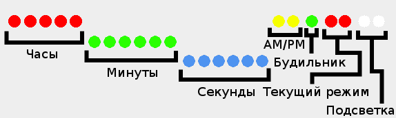
There are 10 types of binary clocks. Some show the time in binary decimal (BCD) representation, the second - in the form of binary numbers. I don’t like BCD watches at all, so I decided to make a pure binary watch. It may be a little more difficult to read than a BCD-clock, but it seems to me that the difference is small, since quickly converting short binary numbers (up to 6 bits) to a decimal number system is not at all difficult. Also, I decided that I would definitely make an indication of the seconds on the clock.
The diode distribution scheme is as follows:
Also, I decided to make 6 buttons:
Set - switch to the clock / alarm / timer setting mode and save the current parameter value in the setup mode.
Mode - switch between the clock, alarm and timer modes.
Up - when setting the clock / alarm / timer, increases the current parameter by one. In the timer and alarm modes, it is responsible for activating and deactivating the corresponding mode. When a signal is triggered - disables the alarm / timer signal.
Down - when setting the clock / alarm / timer, decreases the current parameter by one. In timer mode, pauses the timer without resetting the count to its initial state. When the alarm sounds - the alarm is delayed for 5 minutes (snooze).
24/12 - Toggles between the 24-hour and 12-hour time displays.
Dim - disables / enables the LEDs (with the LEDs turned off, no buttons other than Dim do not work).
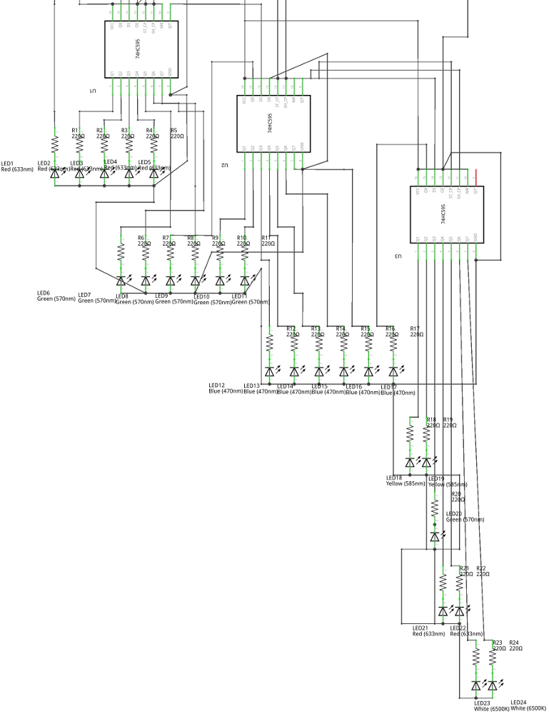
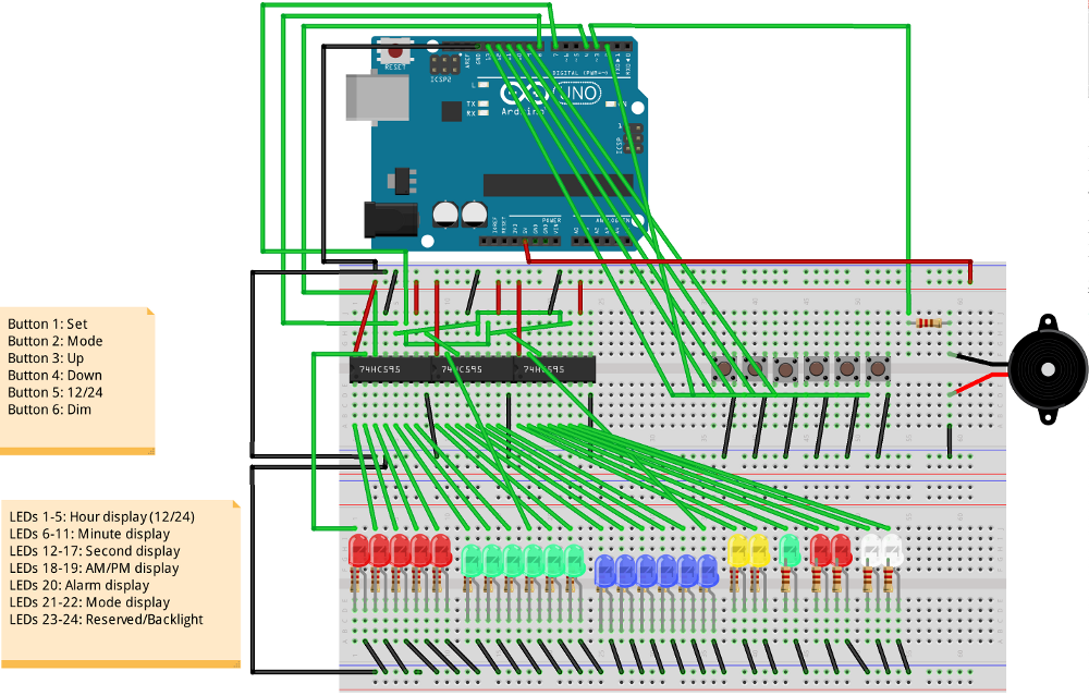
All LEDs must be connected in series with the resistor (I used 220 Ohm resistors), otherwise you can burn not only the diode itself, but also damage the Arduino. The resistor can be connected both to the cathode of the LED and to the anode. We will communicate with diodes through the shift registers 74HC595. This is a chip with 16 pins. They allow you to control a large number of pins using just 3 digital pins on the Arduino.

Pinout 74HC595:
Q0-Q7 - these are the findings of the shift register. We will connect LEDs to them.
Vcc is a pin for power. We apply 5V to it.
GND is the earth. We connect it to the GND on Arduino.
OE - activation of conclusions. This pin is inverted, i.e. to activate the conclusions you need to remove the voltage, and to turn off - on the contrary, apply. In our case, it is not necessary to control this pin, so you can simply close it to the ground.
MR - clear the register. This pin is also inverted and we do not need to control it, so it can be connected to 5V.
ST_CP is the pin responsible for updating the state of the shift register. During recording of a new state, LOW should be applied to this pin, and after recording - HIGH to update the status of the pins. It needs to be connected to a digital pin on Arduino. You can connect all ST_CP on all three registers in parallel.
SH_CP is a pin responsible for register shift by 1 bit. It needs to be connected to a digital pin on Arduino. You can also connect three SH_CP on all chips in parallel.
DS - The pin to which we feed data. It needs to be connected to a digital pin on Arduino.
Q7 '- Pin for cascade connection with other 74HC595. It is necessary to connect Q7 'of the first register with DS of the second and Q7' of the second with DS of the third register. On the third register, Q7 'does not need to be connected anywhere.
It turns out something like this connection scheme:
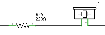
I connected the pie tweezer to the third pin of Arduino in series with a 220-ohm resistor. It should be noted that to work with a piezo tweeter you need a pin that supports PWM (PWM). On Arduino Uno, these are pins 3, 5, 6, 9, 10 and 11.
There were two options with the buttons: either use external resistors, or use the pull-up resistors built into Arduino, which are turned on like this:
The only difference between this approach is that when the button is pressed, LOW will be read, and when released, it will be HIGH, but external resistors will not be required, therefore, I chose just such an option. You just need to connect one side of the buttons to the ground, and the other to the Arduino digital pins.
The final design should have looked something like this:
When I got all the missing parts, I started assembling the device on Breadboard. In principle, the appearance was quite predictable:
Of course, the result was far from what I wanted to get. Still, Breadboard severely limits the freedom to place components. In addition, the bundle of wires hanging over the breadboard does not add aesthetic pleasure. However, the breadboard also exists to collect device mockups on it, and not finished devices.
I decided not to use other people's developments and implement the software part completely independently, from scratch. I started development by writing a subroutine that, when turned on, blinks with all the LEDs and beeps with a piezo tweeter. This allows you to make sure that the chain (not counting the buttons) is assembled correctly and has not collapsed since the last time it was turned on. Many devices do something similar when turned on.
I will not consider in detail the implementation of individual functions, since the sketch turned out to be very voluminous. Therefore, I will briefly review some aspects of the implementation.
Since we communicate with diodes through a shift register, the first thing we had to do was to implement subroutines for convenient work with diodes. The status of all LEDs is stored in the led array of three elements of the unsigned char type and is output through the shift registers at the end of each iteration of the main loop. To simplify the work with diodes, a number of auxiliary functions are implemented, which makes it easy to set the desired bits in led in accordance with the input arguments, for example hours, minutes, etc. I also implemented various effects of diode animation. For example, if the clock is not set, the hour and minute diodes will blink (similar to regular digital clocks, which usually blink “0:00” if they are not set). For second diodes, there is an animation when one diode runs left and right along the strip of second diodes. It is used, for example, in the alarm mode (since second diodes there have no more rational use) or during the clock settings. This gives a more interesting look to the watch.
The main logic of the program, in fact, is a state machine. Depending on the current state, the clock displays the corresponding information, and switches from one state to another when the buttons and timer events are pressed. This is implemented as a large number of nested conditions. At each loop iteration, the state of the buttons and timers and the call of their handlers are checked, after which the state of the diodes is updated.
To process the input, you will need an array containing the state of the buttons (so that when the button is pressed, the handler works only once for each click). When the voltage at the button pin goes to LOW, we set the array element corresponding to the button to true (if it is already true, then we do nothing) and call the click handler. When the voltage returns to HIGH - reset the array element to false. Checking the status of the buttons is implemented as a single subroutine.
The main work is done when the timers are triggered. In the project, I used two timers. One - with a second resolution (for processing the state of the clock, alarm and timer, as well as some animations) and the second - with a resolution of 1/8 second. It is used to display the current time (to increase the speed of the visual response of the clock when changing modes), to animate second LEDs and to give an alarm signal. Both timers are implemented quite simply. Using the value received from millis (), we check whether a certain time interval has passed since the last timer operation, and if the interval has passed, we call the handler and save the new timer operation time. Also, a simple timer adjustment is implemented. If for some reason the timer worked a few milliseconds later,
The full source code for the sketch is available on Github:
From a software point of view, the resulting device worked perfectly (in any case, at first glance). Everything that I wanted to see in the device was implemented and worked stably.
But not without a fly in the ointment. In a practical check, it turned out that the clock is behind by about 1 second per hour, which leads to the accumulation of a very significant error in a short time. A detailed study of the issue showed that the problem was that the original Arduino Uno does not use quartz, but a ceramic resonator for timing, which does not have sufficient accuracy to measure time over long periods of time. The result was a miscalculation - the large quartz resonator on the board is used only for the USB-To-Serial controller and it is not possible to use it for timing. There were several solutions to the problem. The most interesting and convenient option seemed to me to use a real-time clock.
I purchased the Grove RTC module from Seeed Studio. This is a ready-to-use motherboard with a DS1307 real-time clock chip. Also on the board is a clock quartz, three resistors and a battery holder. It looks like this: the

RTC module communicates with the Arduino via the I2C bus. SDA and SCL pins are connected on Arduino Uno to pins A4 and A5, respectively. GND clings to the ground. 5V is already busy with the clock board, so there's nowhere to connect the Vcc RTC module. However, since the RTC module consumes little current (within the permissible load on the digital pins), it can be powered from one of the digital pins, which will be in HIGH permanently.
A ready-made library is available for working with the RTC module on the Seeed Studio website. When implementing work with RTC, the first question arose was how to determine when turned on that it is necessary to read the current time from RTC. For these purposes, it was decided to use the flag in the EEPROM. If the value of the zero byte in the EEPROM is different from zero - we take the time from RTC, if the byte is equal to zero - then we perform the “first run” with the unconfigured clock flashing 0:00. It was also logical to implement at the same time saving the last set alarm time and timer in EEPROM. In order to be able to roll back to the “factory” settings, I expanded the self-test procedure a bit when I turned it on - if you press the SET button while turning on, the EEPROM will be cleared and the device will perform a software reboot (by setting the command counter to 0).
Then I implemented a subset of the necessary functions for working with RTC in the project and it only remained to integrate them correctly into the rest of the code. I transferred from the second timer to a separate second timer, bound to RTC, all time-related handlers. I left the old second timer under tasks that were not critical to accuracy (for example, animation of LED flashing).
Unlike other timers, which are checked at each iteration of the main loop, the RTC timer check is embedded in the timer handler for 1/8 second. Working with I2C is a rather resource-intensive operation and constant polling of RTC in a cycle leads to undesirable effects, such as late timers and distorted sound of a pie tweeter. Checking the RTC timer from the second timer would cause the clock to periodically count down two seconds (because the ceramic resonator of my Arduino is slightly behind real time), and this is extremely undesirable, so processing the RTC in the timer is 1/8 second was the best option.
No matter how good the software part, the appearance of the resulting device still leaves much to be desired. Therefore, I decided to transfer it from Breadboard to a full-fledged printed circuit board. The first thing to do was to make the board layout. For these purposes, I used Fritzing, since I already built a device diagram there and a view of the Breadboard. I did not trust the work of the autorouter and traced the board manually. This process takes some time, but in the end I got a printed circuit board project ready for production:
I decided to order the production of printed circuit boards in China. Seeed Studio has a Fusion PCB manufacturing service. Fritzing can export PCB designs to the Extended Gerber format (RS-274X), which most PCB manufacturers work with (including Seeed Studio). I ordered the production of boards and within two weeks I received a parcel with the boards made: it

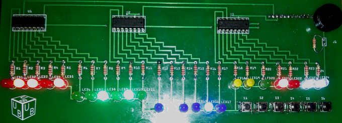
remains only to solder all the components to the board. I’ve never had a chance to solder before, but I quickly got used to it. It seems to me that for the first time it turned out pretty well:

The final result looks much better than the layout on the Breadboard.
I got what I wanted - my own binary clock with an alarm clock and a timer. If you use the battery compartment, you get completely autonomous watches that can stand anywhere. The Arduino platform fully met my expectations and I think that I will use it in my projects more than once.
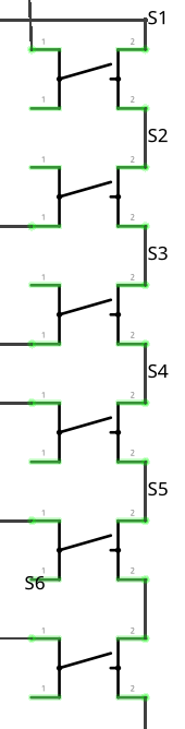
Cascading multiple output shift registers 74HC595
Using built-in pull-up resistors
Binary clock sketch source code
For quite some time now I was interested in the Arduino platform, but my hands didn’t reach it. And now, I recently purchased two Arduino boards and various radio components. Having played enough with a couple of diodes, I decided to collect something useful and interesting. I have long wanted to get a binary watch and quickly realized that the acquisition of Arduino is a great opportunity to make a binary watch to your liking.
From an electronic point of view, assembling a binary clock circuit is not so difficult. I complicated my task and decided not to deny myself the number of buttons and LEDs. According to the initial plan, the project was to go 22 diodes, 6 buttons and 1 piezo buzzer. At first I wanted to assemble a watch on the Arduino Mega, because there are not enough pins on Arduino Uno to manage all this directly, but then I abandoned this idea and decided to purchase several 77HC595 output shift registers, as this is a more rational solution to the problem.
Training
I decided to start by calculating what is needed to build the device on the breadboard. In the end, this is the list:
1 Arduino Uno.
2 Breadboard (full-size, 840 points).
24 LEDs (I took 7 red, 7 green, 6 blue, 2 yellow and 2 white).
25 resistors at 220 ohms.
1 piezo buzzer.
6 clock buttons.
3 output shift registers 74HC595 in DIP-16 package.
Connecting wires and / or jumpers (it took me about 90 pieces).
Grove RTC - Seeed Studio real-time clock module based on the DS1307 RTC chip.
How will it all work
There are 10 types of binary clocks. Some show the time in binary decimal (BCD) representation, the second - in the form of binary numbers. I don’t like BCD watches at all, so I decided to make a pure binary watch. It may be a little more difficult to read than a BCD-clock, but it seems to me that the difference is small, since quickly converting short binary numbers (up to 6 bits) to a decimal number system is not at all difficult. Also, I decided that I would definitely make an indication of the seconds on the clock.
The diode distribution scheme is as follows:
Also, I decided to make 6 buttons:
Set - switch to the clock / alarm / timer setting mode and save the current parameter value in the setup mode.
Mode - switch between the clock, alarm and timer modes.
Up - when setting the clock / alarm / timer, increases the current parameter by one. In the timer and alarm modes, it is responsible for activating and deactivating the corresponding mode. When a signal is triggered - disables the alarm / timer signal.
Down - when setting the clock / alarm / timer, decreases the current parameter by one. In timer mode, pauses the timer without resetting the count to its initial state. When the alarm sounds - the alarm is delayed for 5 minutes (snooze).
24/12 - Toggles between the 24-hour and 12-hour time displays.
Dim - disables / enables the LEDs (with the LEDs turned off, no buttons other than Dim do not work).
Component Connection
All LEDs must be connected in series with the resistor (I used 220 Ohm resistors), otherwise you can burn not only the diode itself, but also damage the Arduino. The resistor can be connected both to the cathode of the LED and to the anode. We will communicate with diodes through the shift registers 74HC595. This is a chip with 16 pins. They allow you to control a large number of pins using just 3 digital pins on the Arduino.
Pinout 74HC595:
Q0-Q7 - these are the findings of the shift register. We will connect LEDs to them.
Vcc is a pin for power. We apply 5V to it.
GND is the earth. We connect it to the GND on Arduino.
OE - activation of conclusions. This pin is inverted, i.e. to activate the conclusions you need to remove the voltage, and to turn off - on the contrary, apply. In our case, it is not necessary to control this pin, so you can simply close it to the ground.
MR - clear the register. This pin is also inverted and we do not need to control it, so it can be connected to 5V.
ST_CP is the pin responsible for updating the state of the shift register. During recording of a new state, LOW should be applied to this pin, and after recording - HIGH to update the status of the pins. It needs to be connected to a digital pin on Arduino. You can connect all ST_CP on all three registers in parallel.
SH_CP is a pin responsible for register shift by 1 bit. It needs to be connected to a digital pin on Arduino. You can also connect three SH_CP on all chips in parallel.
DS - The pin to which we feed data. It needs to be connected to a digital pin on Arduino.
Q7 '- Pin for cascade connection with other 74HC595. It is necessary to connect Q7 'of the first register with DS of the second and Q7' of the second with DS of the third register. On the third register, Q7 'does not need to be connected anywhere.
It turns out something like this connection scheme:
I connected the pie tweezer to the third pin of Arduino in series with a 220-ohm resistor. It should be noted that to work with a piezo tweeter you need a pin that supports PWM (PWM). On Arduino Uno, these are pins 3, 5, 6, 9, 10 and 11.
There were two options with the buttons: either use external resistors, or use the pull-up resistors built into Arduino, which are turned on like this:
pinMode(pin,INPUT_PULLUP);The only difference between this approach is that when the button is pressed, LOW will be read, and when released, it will be HIGH, but external resistors will not be required, therefore, I chose just such an option. You just need to connect one side of the buttons to the ground, and the other to the Arduino digital pins.
The final design should have looked something like this:
Build a device on a breadboard
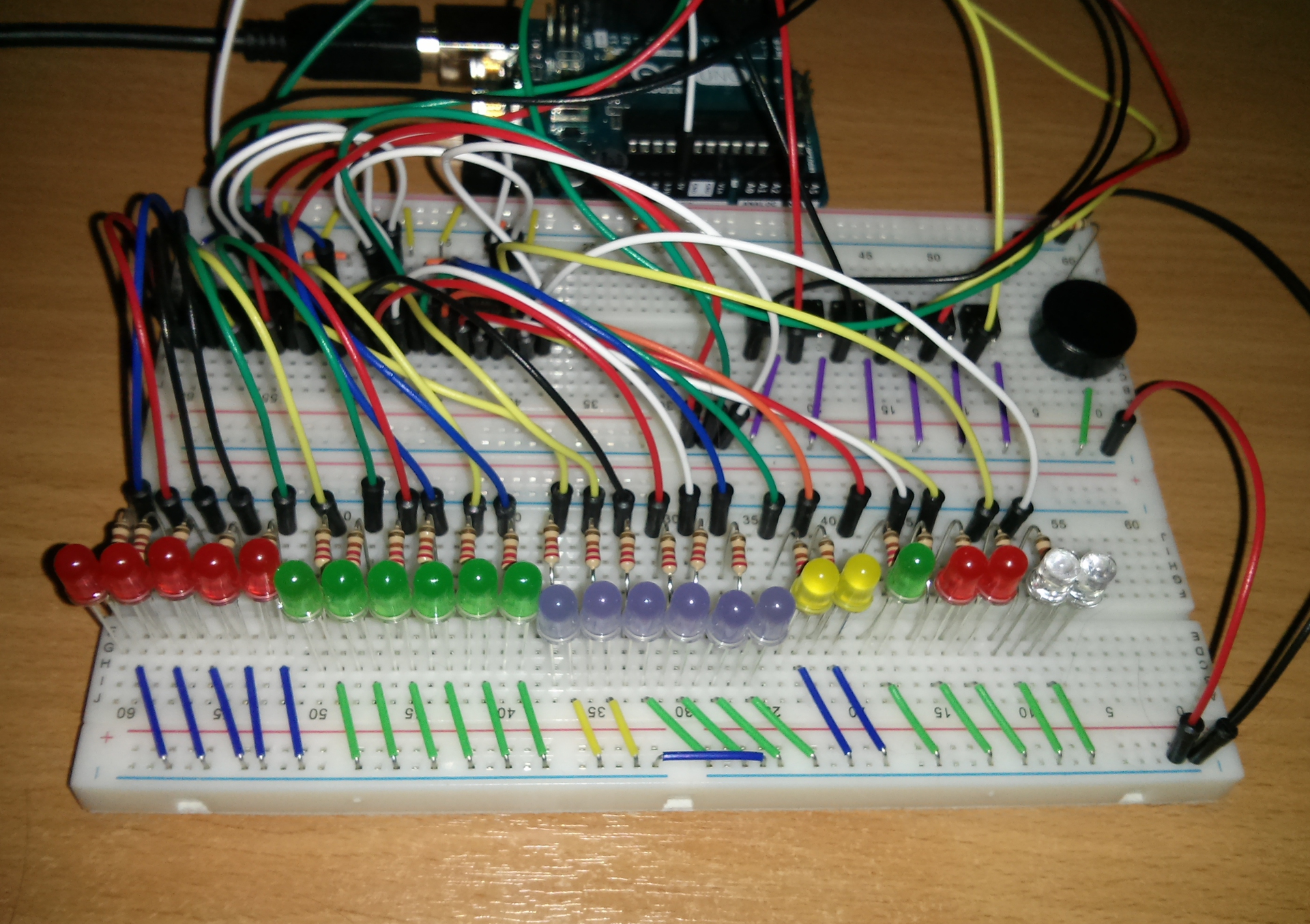
When I got all the missing parts, I started assembling the device on Breadboard. In principle, the appearance was quite predictable:
Of course, the result was far from what I wanted to get. Still, Breadboard severely limits the freedom to place components. In addition, the bundle of wires hanging over the breadboard does not add aesthetic pleasure. However, the breadboard also exists to collect device mockups on it, and not finished devices.
Code writing
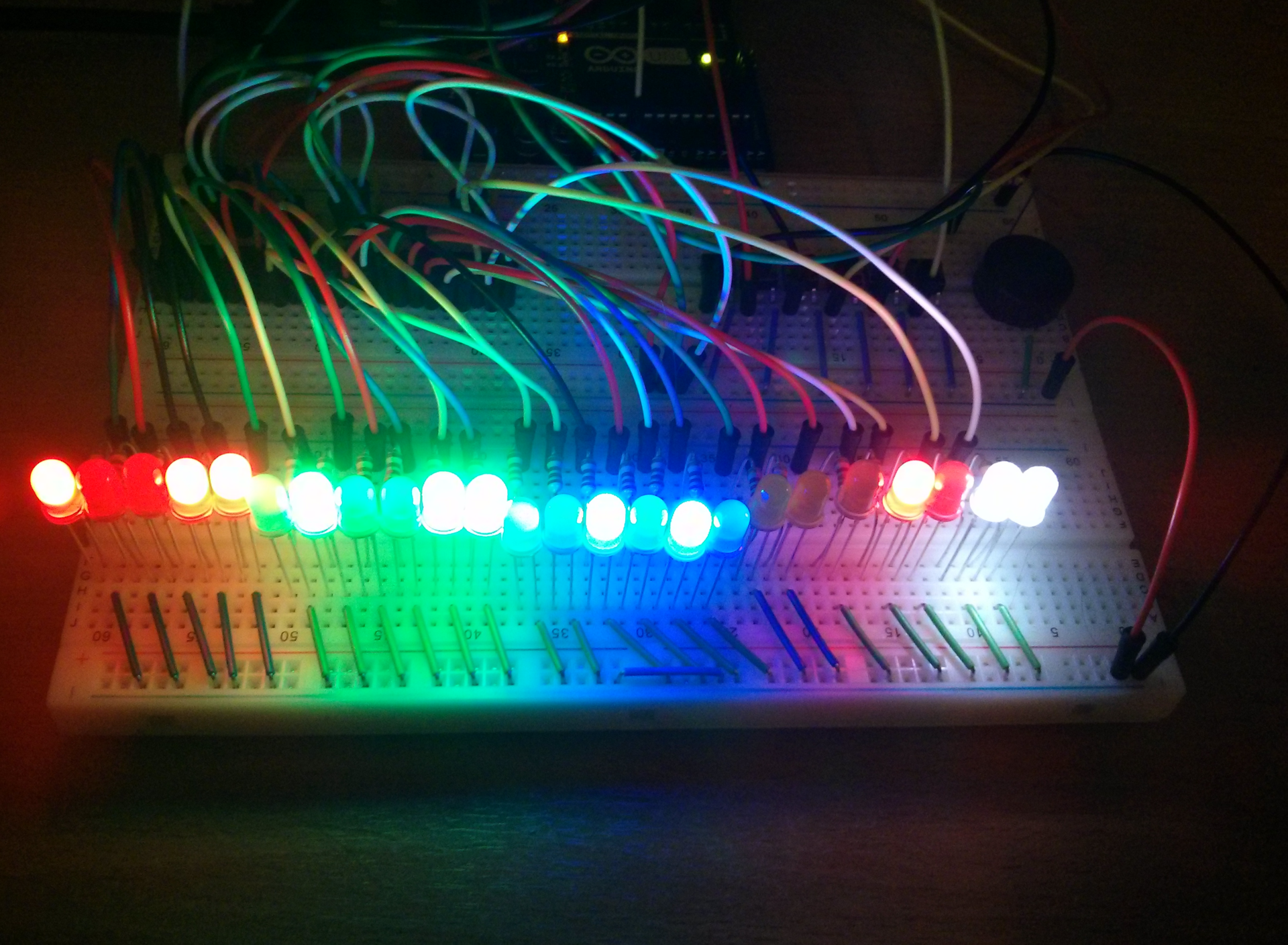
I decided not to use other people's developments and implement the software part completely independently, from scratch. I started development by writing a subroutine that, when turned on, blinks with all the LEDs and beeps with a piezo tweeter. This allows you to make sure that the chain (not counting the buttons) is assembled correctly and has not collapsed since the last time it was turned on. Many devices do something similar when turned on.
I will not consider in detail the implementation of individual functions, since the sketch turned out to be very voluminous. Therefore, I will briefly review some aspects of the implementation.
LED operation
Since we communicate with diodes through a shift register, the first thing we had to do was to implement subroutines for convenient work with diodes. The status of all LEDs is stored in the led array of three elements of the unsigned char type and is output through the shift registers at the end of each iteration of the main loop. To simplify the work with diodes, a number of auxiliary functions are implemented, which makes it easy to set the desired bits in led in accordance with the input arguments, for example hours, minutes, etc. I also implemented various effects of diode animation. For example, if the clock is not set, the hour and minute diodes will blink (similar to regular digital clocks, which usually blink “0:00” if they are not set). For second diodes, there is an animation when one diode runs left and right along the strip of second diodes. It is used, for example, in the alarm mode (since second diodes there have no more rational use) or during the clock settings. This gives a more interesting look to the watch.
Main cycle
The main logic of the program, in fact, is a state machine. Depending on the current state, the clock displays the corresponding information, and switches from one state to another when the buttons and timer events are pressed. This is implemented as a large number of nested conditions. At each loop iteration, the state of the buttons and timers and the call of their handlers are checked, after which the state of the diodes is updated.
Enter
To process the input, you will need an array containing the state of the buttons (so that when the button is pressed, the handler works only once for each click). When the voltage at the button pin goes to LOW, we set the array element corresponding to the button to true (if it is already true, then we do nothing) and call the click handler. When the voltage returns to HIGH - reset the array element to false. Checking the status of the buttons is implemented as a single subroutine.
Timers
The main work is done when the timers are triggered. In the project, I used two timers. One - with a second resolution (for processing the state of the clock, alarm and timer, as well as some animations) and the second - with a resolution of 1/8 second. It is used to display the current time (to increase the speed of the visual response of the clock when changing modes), to animate second LEDs and to give an alarm signal. Both timers are implemented quite simply. Using the value received from millis (), we check whether a certain time interval has passed since the last timer operation, and if the interval has passed, we call the handler and save the new timer operation time. Also, a simple timer adjustment is implemented. If for some reason the timer worked a few milliseconds later,
The full source code for the sketch is available on Github:
We look what happened
From a software point of view, the resulting device worked perfectly (in any case, at first glance). Everything that I wanted to see in the device was implemented and worked stably.
But not without a fly in the ointment. In a practical check, it turned out that the clock is behind by about 1 second per hour, which leads to the accumulation of a very significant error in a short time. A detailed study of the issue showed that the problem was that the original Arduino Uno does not use quartz, but a ceramic resonator for timing, which does not have sufficient accuracy to measure time over long periods of time. The result was a miscalculation - the large quartz resonator on the board is used only for the USB-To-Serial controller and it is not possible to use it for timing. There were several solutions to the problem. The most interesting and convenient option seemed to me to use a real-time clock.
I purchased the Grove RTC module from Seeed Studio. This is a ready-to-use motherboard with a DS1307 real-time clock chip. Also on the board is a clock quartz, three resistors and a battery holder. It looks like this: the
RTC module communicates with the Arduino via the I2C bus. SDA and SCL pins are connected on Arduino Uno to pins A4 and A5, respectively. GND clings to the ground. 5V is already busy with the clock board, so there's nowhere to connect the Vcc RTC module. However, since the RTC module consumes little current (within the permissible load on the digital pins), it can be powered from one of the digital pins, which will be in HIGH permanently.
Code completion
A ready-made library is available for working with the RTC module on the Seeed Studio website. When implementing work with RTC, the first question arose was how to determine when turned on that it is necessary to read the current time from RTC. For these purposes, it was decided to use the flag in the EEPROM. If the value of the zero byte in the EEPROM is different from zero - we take the time from RTC, if the byte is equal to zero - then we perform the “first run” with the unconfigured clock flashing 0:00. It was also logical to implement at the same time saving the last set alarm time and timer in EEPROM. In order to be able to roll back to the “factory” settings, I expanded the self-test procedure a bit when I turned it on - if you press the SET button while turning on, the EEPROM will be cleared and the device will perform a software reboot (by setting the command counter to 0).
Then I implemented a subset of the necessary functions for working with RTC in the project and it only remained to integrate them correctly into the rest of the code. I transferred from the second timer to a separate second timer, bound to RTC, all time-related handlers. I left the old second timer under tasks that were not critical to accuracy (for example, animation of LED flashing).
Unlike other timers, which are checked at each iteration of the main loop, the RTC timer check is embedded in the timer handler for 1/8 second. Working with I2C is a rather resource-intensive operation and constant polling of RTC in a cycle leads to undesirable effects, such as late timers and distorted sound of a pie tweeter. Checking the RTC timer from the second timer would cause the clock to periodically count down two seconds (because the ceramic resonator of my Arduino is slightly behind real time), and this is extremely undesirable, so processing the RTC in the timer is 1/8 second was the best option.
We give the device a complete look
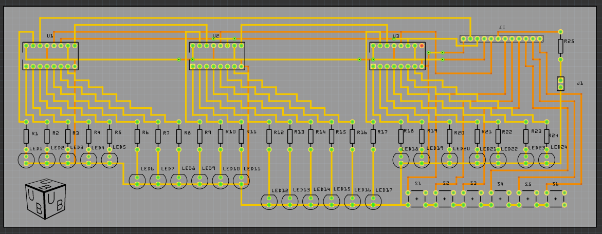
No matter how good the software part, the appearance of the resulting device still leaves much to be desired. Therefore, I decided to transfer it from Breadboard to a full-fledged printed circuit board. The first thing to do was to make the board layout. For these purposes, I used Fritzing, since I already built a device diagram there and a view of the Breadboard. I did not trust the work of the autorouter and traced the board manually. This process takes some time, but in the end I got a printed circuit board project ready for production:
I decided to order the production of printed circuit boards in China. Seeed Studio has a Fusion PCB manufacturing service. Fritzing can export PCB designs to the Extended Gerber format (RS-274X), which most PCB manufacturers work with (including Seeed Studio). I ordered the production of boards and within two weeks I received a parcel with the boards made: it
remains only to solder all the components to the board. I’ve never had a chance to solder before, but I quickly got used to it. It seems to me that for the first time it turned out pretty well:
The final result looks much better than the layout on the Breadboard.
Conclusion
I got what I wanted - my own binary clock with an alarm clock and a timer. If you use the battery compartment, you get completely autonomous watches that can stand anywhere. The Arduino platform fully met my expectations and I think that I will use it in my projects more than once.
References
Cascading multiple output shift registers 74HC595
Using built-in pull-up resistors
Binary clock sketch source code