Developing a hexapod from scratch (part 1) - designing
Hello! Not so long ago, I began to learn programming under microcontrollers. At the beginning, writing simple programs for blinking with an LED and even two was no longer pleasurable and boring. And one evening, sitting in thought over what to occupy his head with, he decided to find more complex projects. On the Internet, I saw a lot of things that people create, but most of all I was surprised by a six-legged robot or a hexapod.
Inspired by the pictures and video decided to test their strength. Development of housing, electronics and software will be conducted from 0.
So, part 1 - the development of a 3D model of the body
Initial materials and components for the future robot:
0. Arduno Due (we will write in Atmel Studio on pure C without Arduino IDE, at the same time I will tell you how to connect a debugger to this board) - 1pc;
1. HLK-RM04 (UART to WIFI converter) - transparent bridge with UART to WIFI - 2pcs;
2. MG996R servo-drivers (from China, as without it) - 18 pieces;
3. LM317D2T-TR for powering servos + small distribution in the form of resistors and capacitors;
4. CAD "COMPAS 3D";
5. 3mm plywood as a material for the body (cheap and it smells delicious);
6. Ability to order laser cutting;
7. Time. A lot of time.
At the very beginning of the journey, the question “What kind of corps do I want?” Arose. In the process of finding the answer to this question, I came across several ready-made solutions. Most liked PhantomX and A-Pod. Looking at the case, I decided to start development already, but no. The following problem appeared: since I didn’t see these robots in my eyes and didn’t hold them in my hands, I had a bad idea about their dimensions. In search of a solution to this problem, I came across one of the articles on the site. The author of the article tomnewmann kindly shared with me the drawings of his project, for which he thanks a lot.
After evaluating the dimensions of the future parts and having thought a little over all the information received, I began to outline the casing drawings. I thought it would be wiser to start with the design of the legs, as they are the most difficult part of the body.
Coxa
After several hours of reflection, the first model “Coxa” appeared (this is the way to designate the knot connecting the leg to the body). The node tried to make as compact as possible. The servo will be completely inside, respectively, do not forget (as I did the first time) about the hole for the output wires.
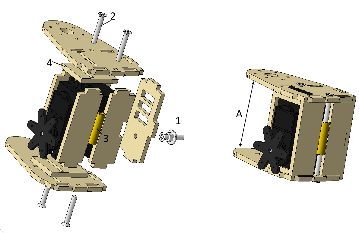
Detail 1 - The axis on which Femur will be mounted (second leg). Assembled from M3x15 screws, M3 washers and nuts.
Part 2 - Screw M3x20.
Part 3 - Rack for printed circuit boards M3x20.
Part 4 - They are a kind of servo-locks to prevent it from moving vertically.
The height (A) of this node must be done in such a way that a servo that fits on the frame can fit inside.
Femur
Next you need to do "Femur". The detail turned out to be the simplest of all, and I think it does not need comments.
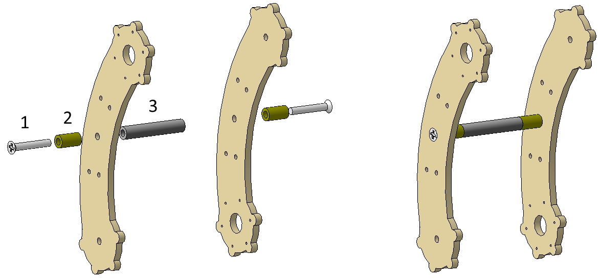
Detail 1 - Screw M3x20
Detail 2 - Plastic sleeve 3x10 (I did not find a long rack, I had to look for other solutions)
Detail 3 - Rack for printed circuit boards M3x30
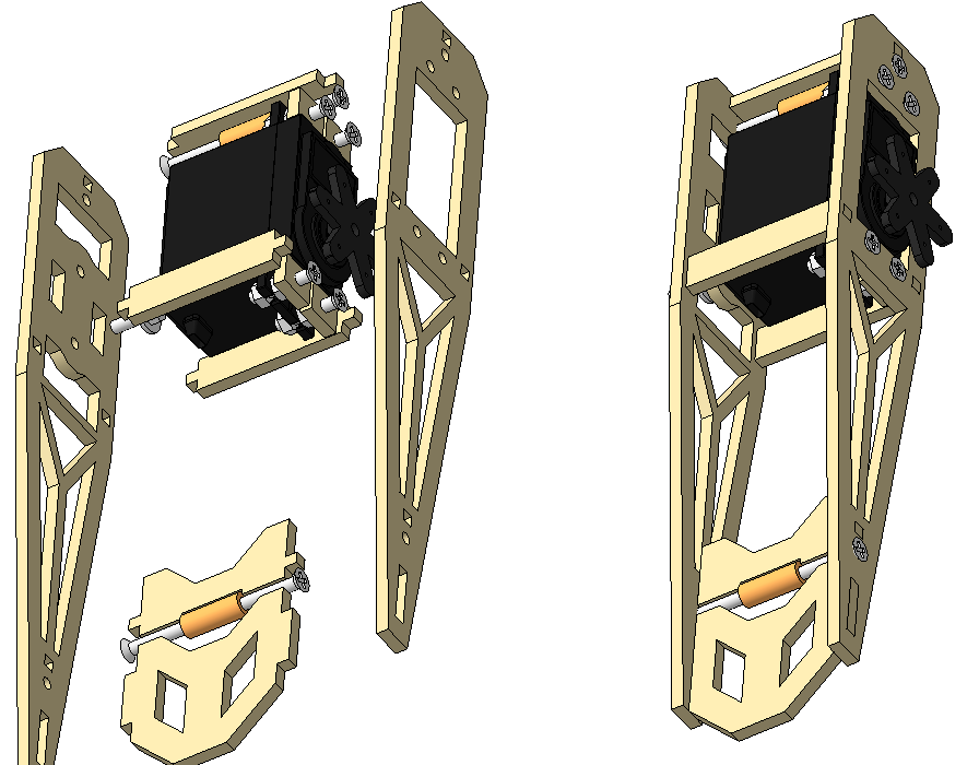
Tibia
The next part is Tibia, the last part of the leg. There should be no problems with it and its length depends on the height at which it is planned to understand the robot. I have it 130mm from the servo axis, I didn’t do any more, because with increasing length, the load on the servo drives also increases, especially on the servo drive in “Coxa”. On the second side, I made a second hole for the axle so that the servo could be turned over and the lever length was reduced, if suddenly the servo would be hard.
Frame
Next in line is the frame - the largest part. That it determines the configuration of the legs of the future robot. There are several options for the location of the legs, but I settled on the version of the letter F (when viewed from above it looks like).
At the first stages of the design, the question arose: “And how far apart should the legs be from each other?”. In search of an answer to this question, I realized that there were no recommendations on this issue. Studying other people's projects and gait options, I concluded that the distance is selected based on the desired maximum angle of rotation of the limb. The greater the distance between the legs, the greater the angle can reach the limb while walking.
The tomnewmann drawings helped to resolve this issue ., of which I took the distance between the legs, since the dimensions of the robots were quite similar (mine is a bit smaller). A few hours later, the upper and lower parts of the frame were born:
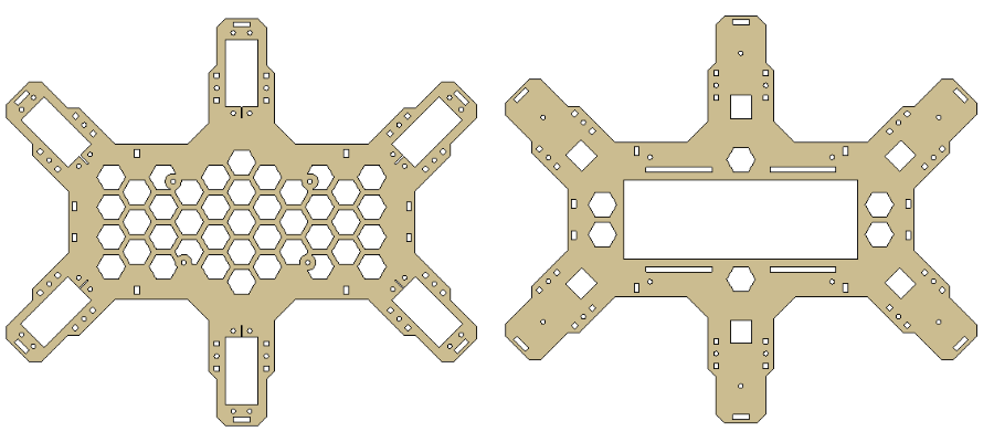
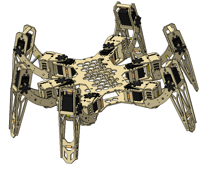
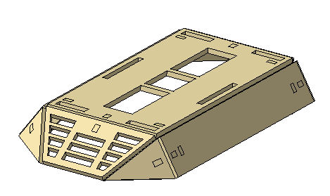
In the lower part of the frame, a cutout was made for the battery and its fastenings. By the way, it will be mounted on velcro, which are used on quadrics when attaching batteries to them. The frame turned out pretty big. After sitting 1 more evening and making the intermediate parts in the form of supports between the parts, I decided it was time to assemble the frame with the installed servo drives. The result did not take long to wait:
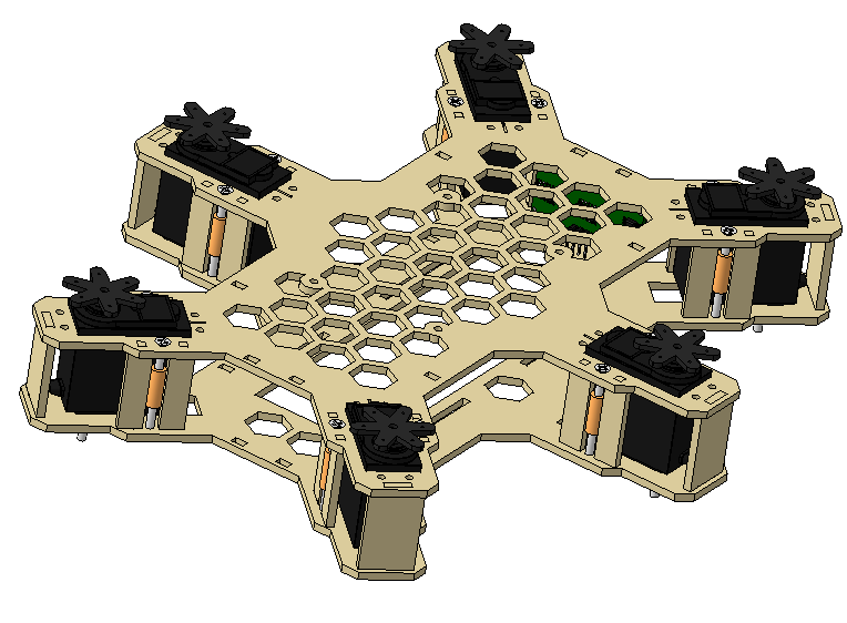
Since we already have all the necessary components, we can make a complete assembly of the case:
In the center of the case between the plates was planned to be located the power supply for the servos, the bottom of the 3S Li-po battery, and the top control board (Arduino Due). In accordance with this, I changed the frame assembly: The
board on top is the Arduino Mega model with some kind of shield. It is used simply for the view and has the same dimensions as the Due.
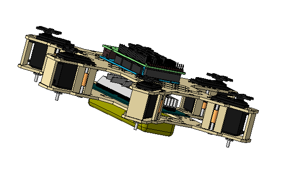
It looks not very nice, but taking into account the wires that will stick out it will be even worse. In addition, the body seemed to me very thin. I decided to cover the electronics as much as possible without affecting the appearance and come up with a name for my brainchild.
The solution to the first task was the top and bottom covers covering the batteries and control electronics. These are the only parts that will be assembled with glue. Later in the evening, the bottom cover model was born.
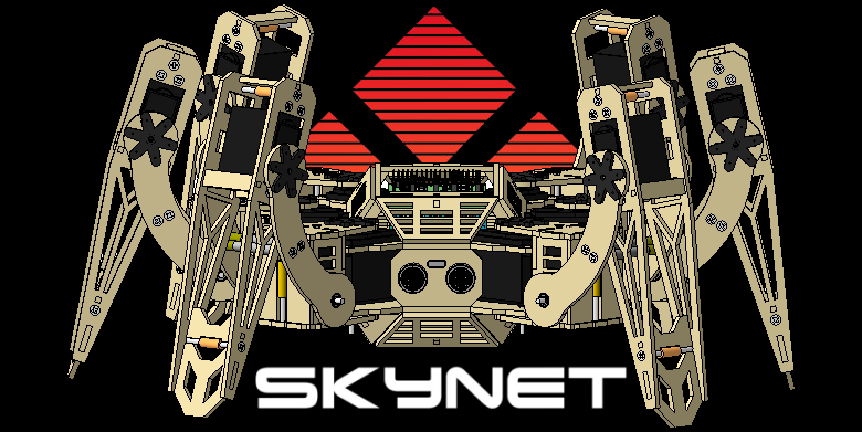
If with the first task there were no problems, then with the second task there were difficulties for 2 days. Yes, it took me so long to just think of his name. Accidentally recalling the movie "Terminator" decided to call it "Skynet" and cut out the name on the top cover. Also added cutouts for HC-SR04.
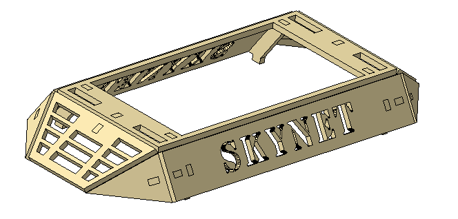
As a result of adding only two roofs, the hull significantly changed the appearance for the better:

The result I was very impressed with and the appearance is quite attractive. In the second part I will talk about the assembly of the hull and the rake, which I attacked.
PS
- Drawings: drive.google.com/open?id=1KHteI6MK5aWlVP0mCM4DmjNJArnF98Ur .
- I will be glad to any criticism and ready to answer any questions within this material.
Links to other development stages
Part 2 - assembly
Part 3 - kinematics
Part 4 - trajectory mathematics and sequences
Part 5 - electronics