Expansion of network capabilities of a programmable relay using WI-FI
How it all began
It all started with the development of algorithms for the PR200 programmable relay, and often required visualization or input of information from a computer, for this it is necessary to use operator panels or SCADA systems, but this is not always convenient, and is it necessary for simple systems. The solution was found quickly, and over time I tried to improve and facilitate my work in this direction as much as possible, what came out of it read further.
It's about the WI-FI network card and its capabilities.
Since this board is used for debugging various projects, the interaction interface is constantly modified for more convenient and quick setup. The first modification was a simple RS-485 to TCP converter with output to WEB, with ready-made firmware known in the ESP8266 community. More than 2 years have passed since then, it took archives to analyze the processes stretched in time, and since I wanted to combine all this in one device without additional equipment, it was decided to build in support for microSD, which greatly simplified the analysis of processes with the ability to quickly access archives. The second modification of the board had a slot, with the ability to remove the microSD card to save the recorded files on the computer. It seemed to me not very convenient, and a version appeared with the ability to download files via WI-FI. Sometimes downloading does not happen to the end and a repeated download operation is required, but considering that at this time the equipment remains in operation and archiving can also work, I think this is not a very big problem. Also tested version with a memory chip of 16 mB instead of a microSD card. Faster downloading, but there is no possibility to save a lot of files, the recording goes sequentially until the entire memory is full.
Purpose and capabilities of the interface board
The board is designed to expand access to the internal variables of the logic of the programmable relay PR200, and provides access to both read and write variables.
Thanks to the wireless WI-FI interface, access to the device is provided without the need to connect additional equipment. First of all, the solution is focused on projects of simple home automation in places with the presence of WI-FI networks. These include automation solutions for lighting both internal and external, management and monitoring of pumping stations, greenhouses, etc. Due to the built-in WEB server in the board, there is no need to purchase additional equipment for those cases when access to the system is needed infrequently. Basic input output is carried out using a smartphone / tablet or PC located in the same network.
The interface board can operate in various modes. When connected to a router with Internet access, it allows you to remotely monitor the status of variables in the logic of the PR200, as well as to control the algorithm through network variables in formats supported by the PR200 in the Slave mode.
Communication with the programmed algorithm in the device is carried out through network variables, while the interface board can act as a Master or Slave. The standard speeds and settings of the PR200 network interface are supported. The exchange via the Modbus TCP protocol is supported; for this, a memory area of 100 cells is allocated, which can be accessed from both the WEB interface and the Modbus RTU protocol from the PR200.
The choice of the network card mode is similar to the choice when working with graphic panels; working in the Master mode allows you to more flexibly control the exchange of variables; for registers whose value is to be received more often than the others, it is possible to set the polling period less. The following commands are available for the Modbus protocol:
03 (0x03) Read Holding Registers Read.
04 (0x04) Read Input Registers Read
06 (0x06) Preset Single Register Record
16 (0x10) Preset Multiple Registers Record
Variables obtained from the relay are available for writing to a file (archive), which is placed on the micro SD card, recording is carried out in text format. After downloading, you can view on a computer in a simple text editor. The values recorded in the file can be displayed on a historical chart. Using the options of scaling and selecting a specific period on the timeline, as well as the individual showing / hiding lines of the graph, the analysis of historical data is carried out.
Files created by the archiver remain on the microSD card and can be downloaded to a computer, only one file is available at any time, it can be recorded archive data, reading information to build a historical graph or reading information to save to PC .
For archiving, variables from the address space of the network board are available, in which you need to write data received via Modbus RTU from the PR200 or Modbus TCP from other devices supporting the Modbus TCP protocol in the master mode.
The interface board can be configured both in the access point mode (Access Point) and in the client mode - the workstation (Station), and maybe in both modes simultaneously. Most often, the access point has Internet access and works as a bridge between the device and the network.
A wireless connection can be protected with a password, there is also the ability to hide the access point.
Variables received via the RS485 interface from the PR200 can be analyzed by presenting them in graphical form, in this mode, the values will be displayed in real time with a period of ~ 1 sec.
There are 10 variables available for plotting in integer format, floating point or in bitwise representation of 16/32 bits. The number, type, addresses of variables and output format are taken from the archive settings.
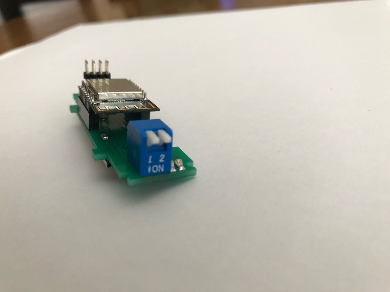
For quick and convenient work, it was decided to repeat the form of the device’s “native” network board.

The board is installed in the device.
Network card can be installed in the first or second slot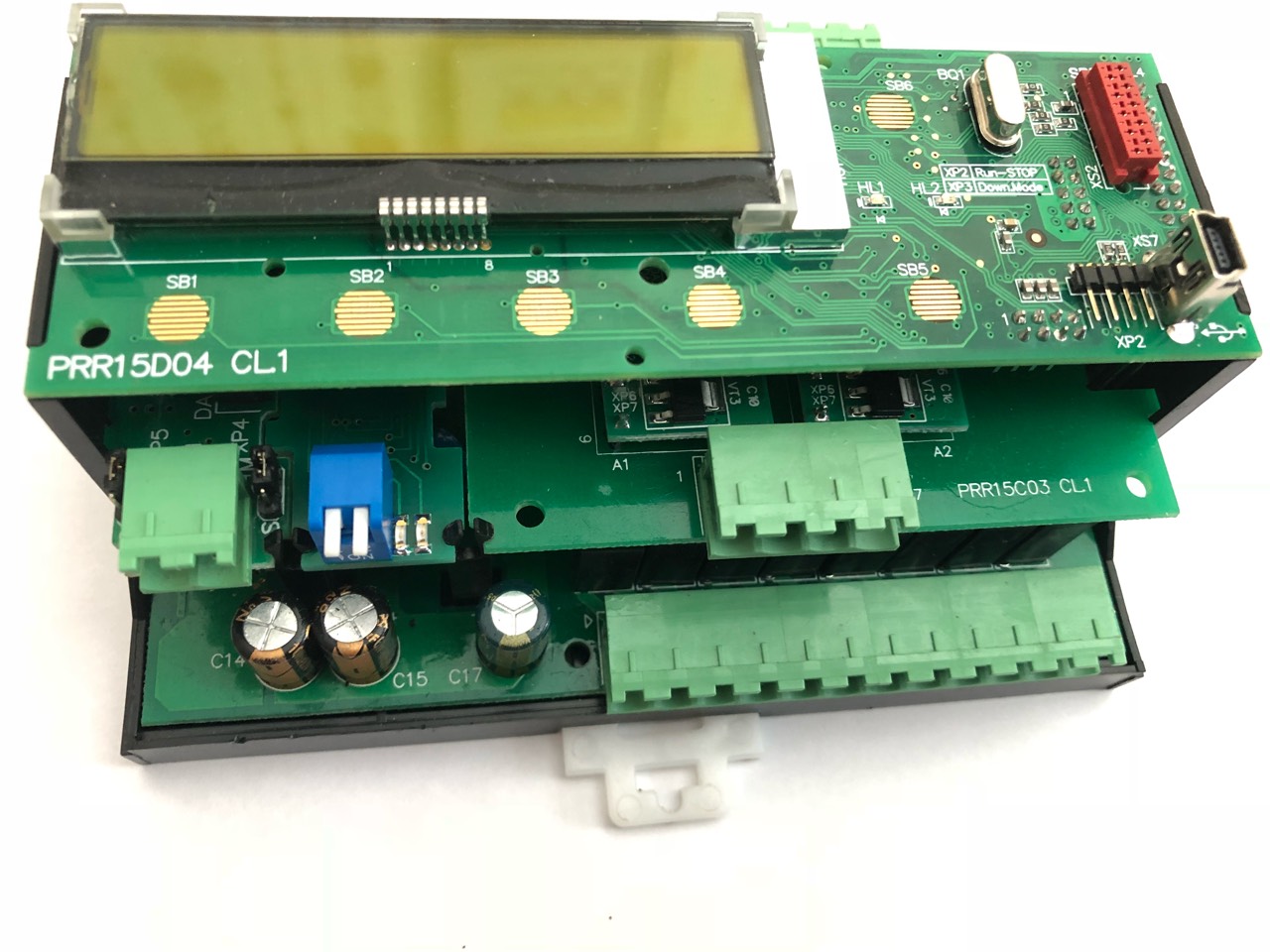
The board has two switches, one serves to reset the network board (does not affect the operation of the program in the PR200), the second switch can be programmed to enable archiving (selected via settings from the board's WEB interface). There are also 2 informational LEDs:
1-blue briefly lights up when exchanging data over the RS-485 interface with the PR200
2-red briefly lights up when data is written to the micro SD card, and it is turned on permanently if there is no card or it is impossible to read the data on the card.
The following are the main menus when working in different modes:
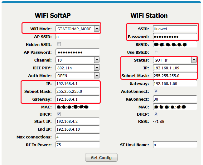
Basic network settings for connecting via WEB.
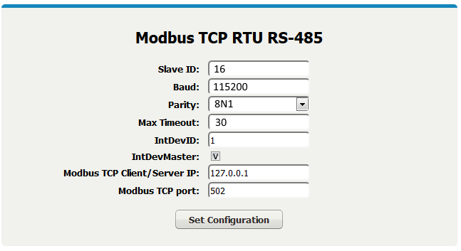
Settings for connecting to the PR200 network interface and settings for connecting via Modbus TCP via WI-FI
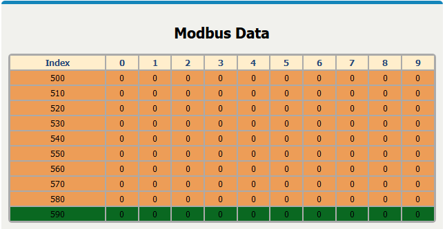
Map of internal registers common to Web, Modbus RTU and Modbus TCP
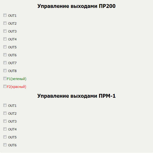
A test WEB page for controlling and monitoring the I / O states of the PR200 with the PRM-1 expansion module connected.
Pages for input / output of values from the PR200 and data transfer to the control outputs of the device.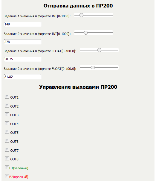
When connecting a network card to a router with Internet access and port forwarding, remote work with the card through a browser is possible.
How it works
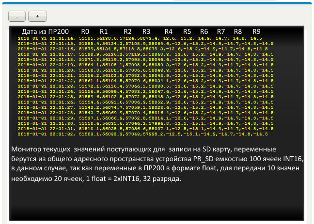
Below are screenshots of the PR200 on a real project, with data archiving. A project is loaded into the PR200, which reads the values of 4 analog channels to which NTC sensors are connected and converts these values to temperature via a second network interface configured in Master mode, and the PR200 polls the MB110-8A module to which 2 DTs Pt1000 are connected. Thus, data is collected on 4 resistance values from the analog inputs of the PR200, 4 temperature values obtained using the NTC macro, and 2 temperature values received from the MB110-8A module via RS-485. All 10 registers in the float format on the first network interface configured in the Master mode are read for writing to the archive and WEB visualization.
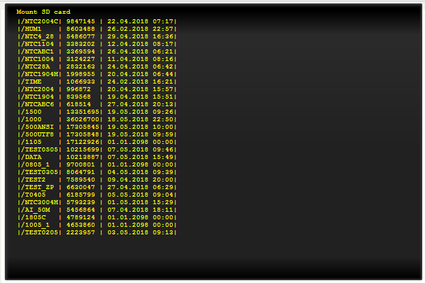
The menu for working with the SD card, with archiving turned off, displays a list of files on the card, while archiving is enabled, displays a log of the recording on the card.
Archive management menu.
The time stamps for archiving are read from the real-time clock registers of the PR200; in this example, the clock is not synchronized with real time.
Archive file downloaded via WI-FI with micro SD installed on the board and opened with a text editor. Ready for plotting.
A page opened in the browser for plotting a graph from a downloaded file.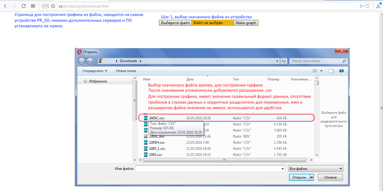
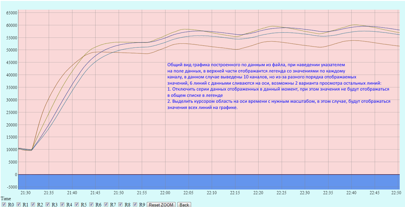
Formed graph according to data from the archive file.
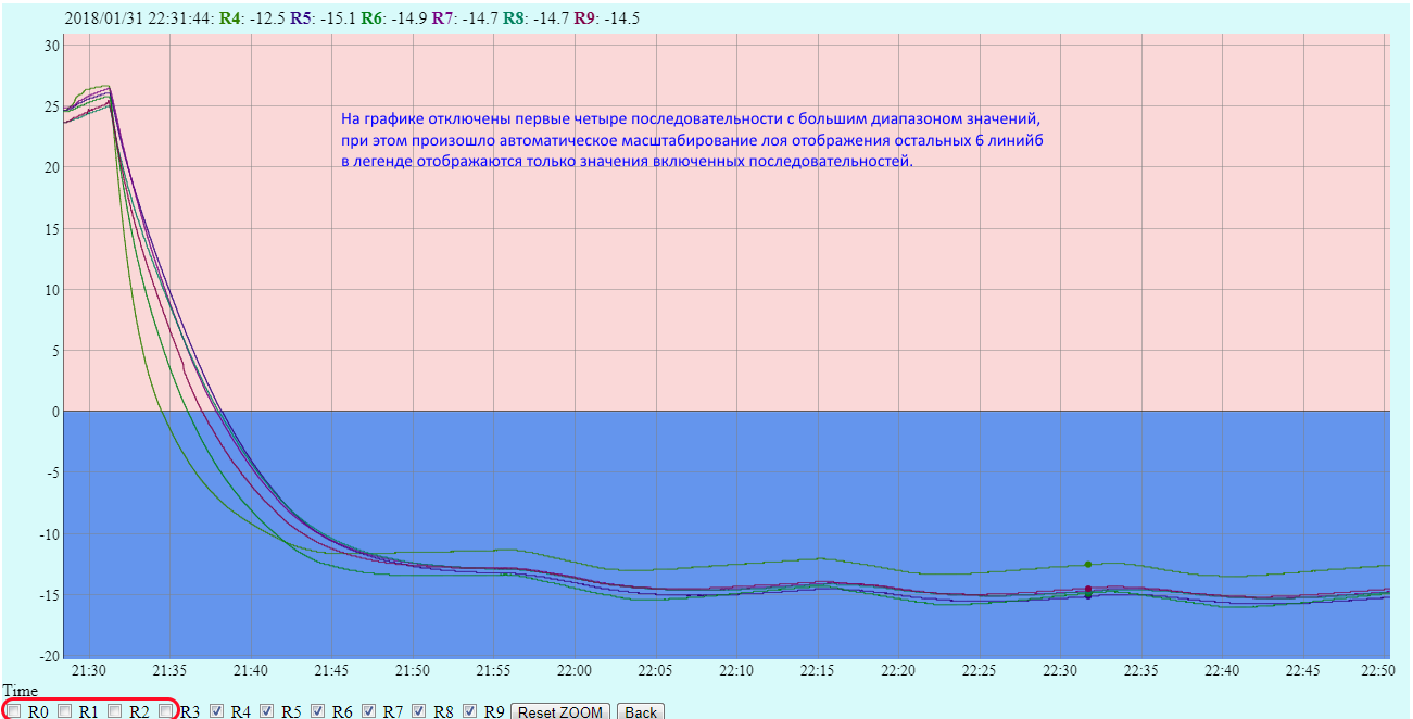
Manage the visibility of graphs through the legend
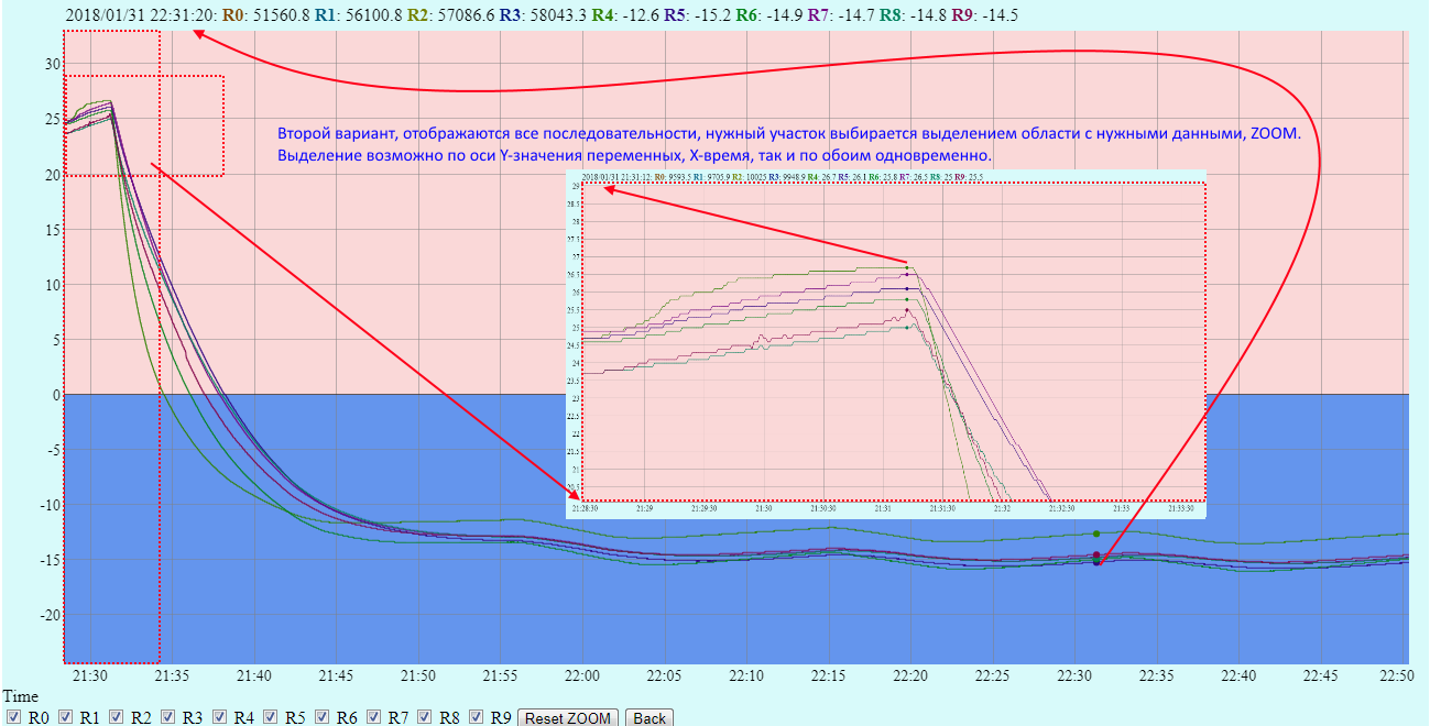
Detailing the necessary areas on the graph.
Access to registers via Modbus TCP (WI-FI)
If the WEB capabilities are not enough to build visualization, then using access via Modbus TCP, you can organize communication with SCADA systems and quickly create the necessary visualization from ready-made blocks. Using various network monitors, you can monitor the status of the internal registers of both the network card and the embedded registers of the PR200. An example of a survey using the program Modbus Poll.
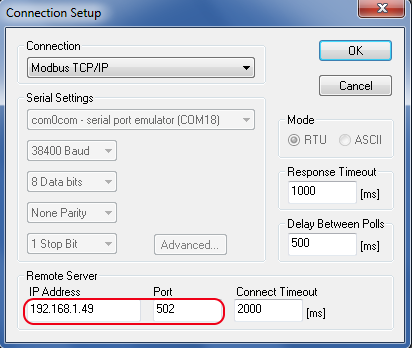
Connection via ModBus TCP using Modbus Poll.
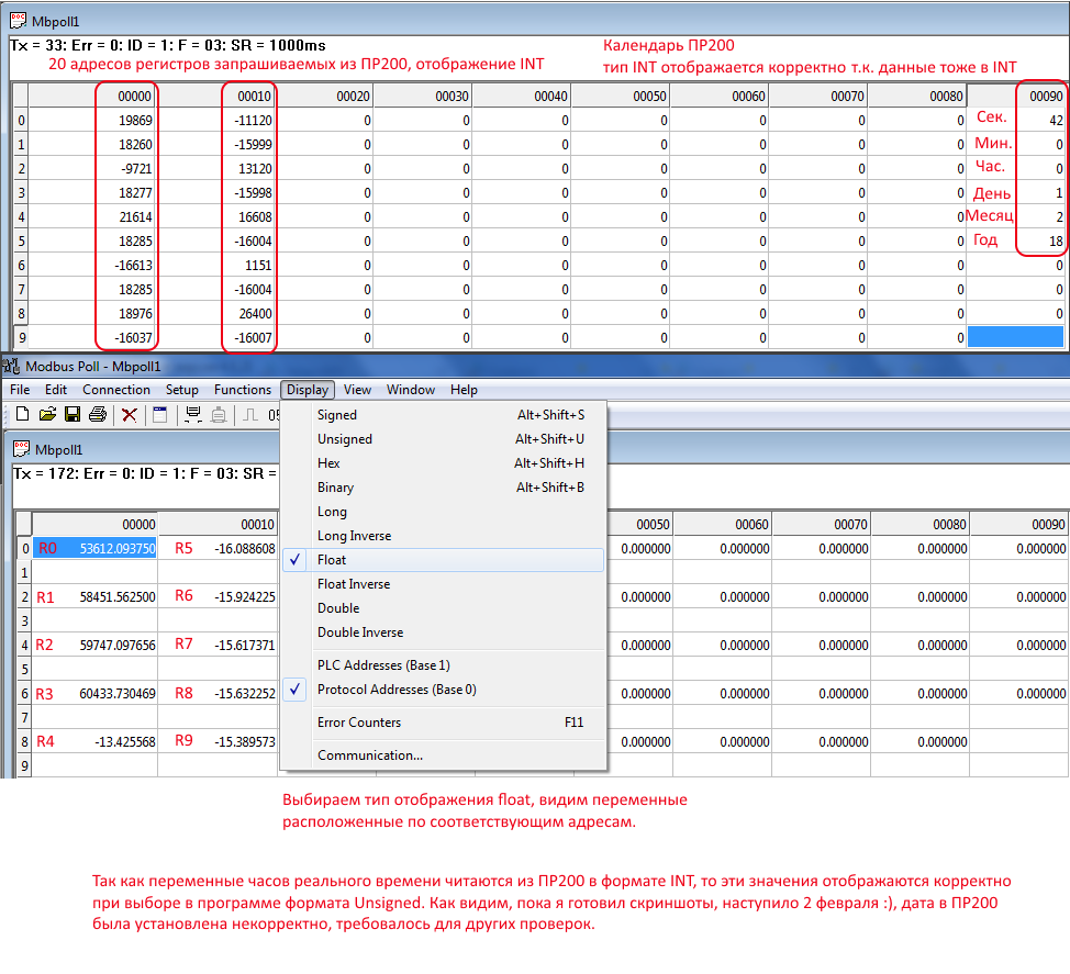
Reading registers, and presenting them in various formats.
findings
After installing the network board in the device, additional features and tools appear in the work with the programmable relay PR200. Different usage scenarios are possible both individually and in combination mode.
One example, the recording of archived events in the PR200, currently has various macros for recording archived events in the device, but they occupy a lot of resources in the device and have limited capabilities both in information output and in depth of archiving using an external drive. more flexibility to configure and record the desired events. To facilitate the analysis, a register recording mode in bit mode has been added, so a 16 or 32 bit number decomposed into bits falls into the archive. Various modes of starting archiving are supported, through a switch on the board, a WEB interface, a ModBus register. Using the ModBus register, the device itself determines the moment of recording, by writing a number different from “0” in the cell, the setpoint is exceeded, we write to the register “1” and the logs are written until the value is written to the register “0” similar to triggering input signals. Separately, you can select a record with a certain period of different data on temperature, pressure, humidity for subsequent analysis in a graphical representation. To convert data into a graphical form embedded web page in the device.
The second scenario is remote control, or monitoring of the state of internal variables, change of operating modes. This option can be divided into local, within the internal network, and through the Internet.
The remaining options are auxiliary, debugging, outputting the variables of interest to the current visualization, viewing network variables, etc.
It is interesting to hear the opinion of the community on this topic, who can solve similar problems in what ways?