Wrapping. Technology
Previously, in order to debug the electronic circuit, I used breadboards , hung the nozzles , used the wiring wire and resistor terminal trim for connections . Tracing was done on the fly, often with errors, which sometimes rendered parts unusable. Such installation has many problems: it is difficult to change the circuit, the wires fall off from vibration, it is difficult to reduce several wires at one point, etc.
There are other ways of prototyping, but today I will remind you about wraparound editing [ 1 , 2] - time-tested technology, convenient and reliable for prototyping and prototyping. Moreover, using this technology, it is possible to create end devices that will work reliably for many years.

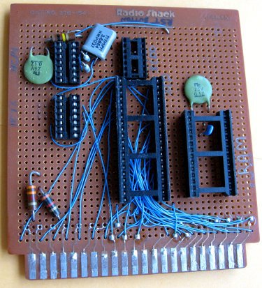
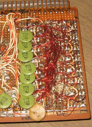
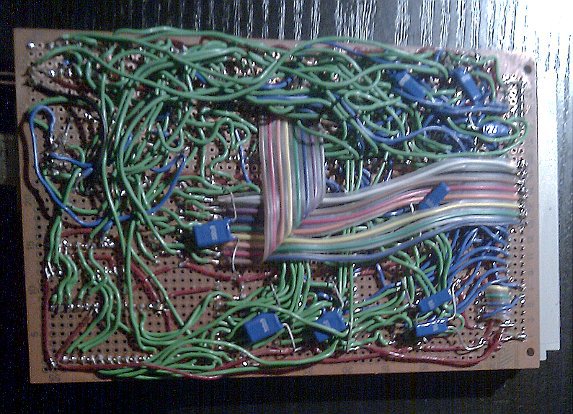
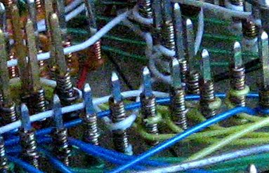
Examples of how NOT to make breadboards
That's what prototyping on a breadboard with a wiring wire can lead to. Is it worth talking about the reliability of such boards?

Wire wrap
Wrapping is a technology for building electronic circuit boards without making a printed circuit board . Wires are wrapped manually or using machines, and the connections can later be changed manually afterwards. The method was popular in mass production in the 60s and early 70s and continues to be used for small batches and prototypes.

PC compatible with IBM PC / XT - Neuron I9.66 - 1987
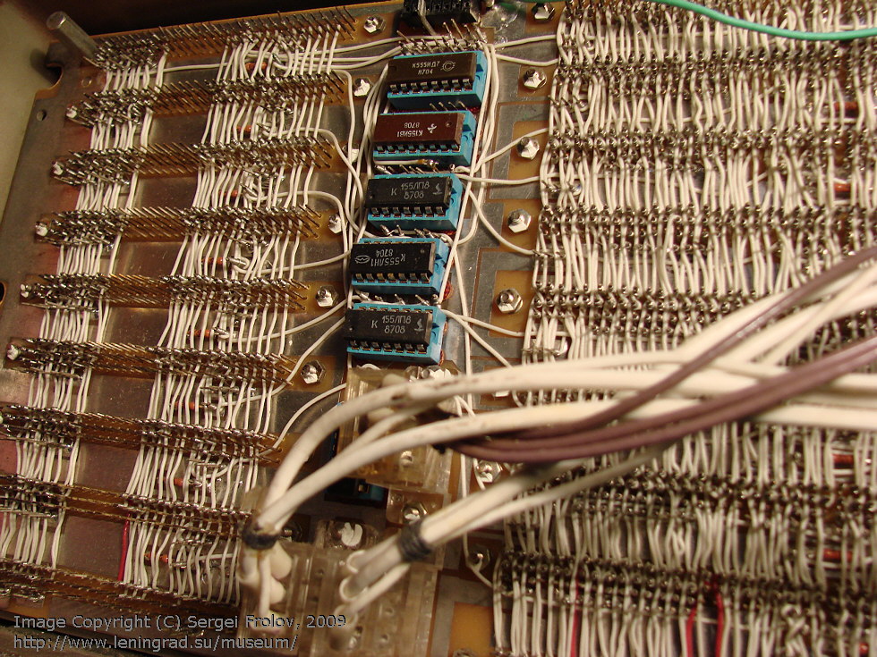
The method is popular and now
project BMOW (clickable) project Symbolics 3600 Project 6502 and many other modern hardware projects prototipiruyutsya via Wire Wrap

FAQ
Q: Is wrapping reliable?
A: Yes, if everything is done correctly (the connection points must not be touched). From Wikipedia: a properly wired wire connection is seven turns of the wire (4 × 7 = 28 contact zones), and a half turn of an insulated wire to weaken possible mechanical stress . The idea is that by tightly wrapping a clean wire over a clean pin contact, we do chemical welding at each edge of the pin contact. The quality of the electrical connection does not depend on the oxidation on the outside of the resulting spiral, although over time it will not look beautiful. Also, the connection is not afraid of vibration. If you dismantle the wound wire and try to touch it, you will understand what it is about.
Q:Do I need to solder wire wrapping?
A: This is not necessary, the boards work for decades. If problems arise, then this is the result of sloppy work. An exception is the wrap around the contacts of round-section radioelements - they need to be soldered.
Q: Where is wrap-around editing applied and to what frequencies does it work?
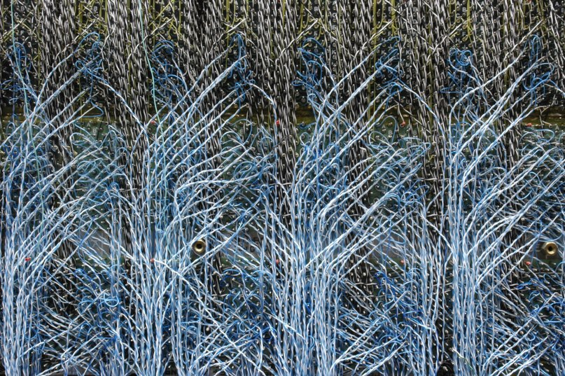
A: Wrapping method was used to build prototypes of high-frequency circuits and circuits of small circulations; including gigahertz microwave circuits and supercomputers . The method is unique in that the connection length can be precisely controlled, and twisted pairs or magnetically shielded fours (four wires) can be laid together. Installation of the Apollo spacecraft onboard control computerwas produced by just such a method ( photo [ 5 ]).
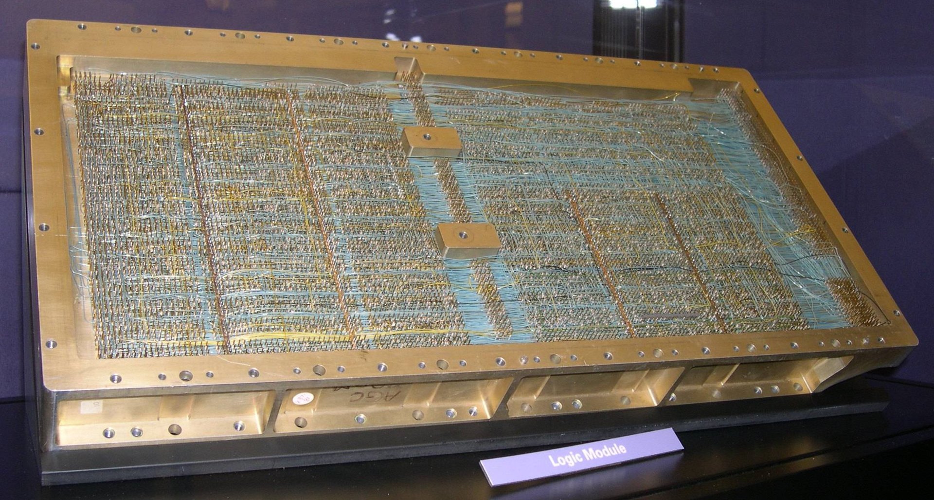
Q: What tool is used for installation?
A: There were fully automatic mounting systems. Semiautomatic devices, when the contact is wound with one click. Completely hand tools. We will talk about a hand tool.

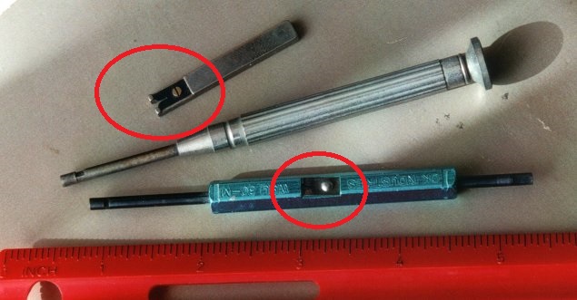
The tools shown in the figure are used for each wire diameter, they wind the wire with one end, the other is used for dismantling. The handle has a hole and a knife for stripping the wire from insulation.
Q: If the tool is not universal, then what diameter can the conductor be used?
A: On ebay you can find tools for diameters 19, 22 , 28, 30- AWG (this is an American caliber, respectively 0.9, 0.6, 0.32, 0.25 mm)
Q: Will any copper wire work?
A: I can’t say for sure, it looks like the wire has a special coating. On ebay, wire is called Wire-Wrapping Wire 30AWG . Although I saw designs with copper wire.
Q: How to make a wrapping?
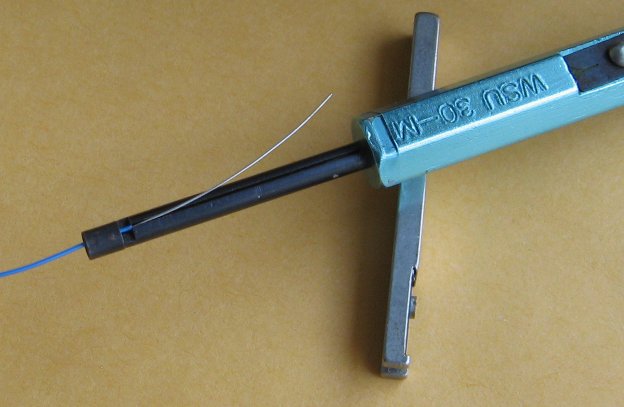
A: First, we strip the wire a couple of centimeters with a tool. Do not touch the stripped wire with your hands!
We insert the wire into the hole with the edge, and not only the stripped part, but also about 4 mm with insulation
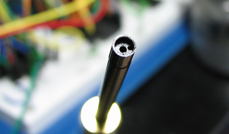
Next, set the tool with the central hole on the contact and make several revolutions. Skill comes quickly with experience. It should get 1.5 turns with insulation and 7 turns of stripped wire. For most instruments, the direction of rotation (clockwise or counterclockwise) does not matter.
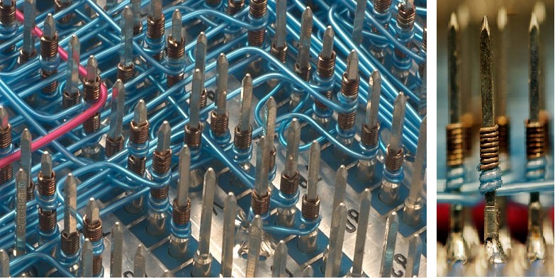
In the end, it should look something like this:
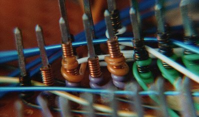
As you can see in the photographs, the silver-plated wire oxidizes and darkens, like copper. But the area where the wire connects to the pin is oxidation resistant.
Own experience
In my small projects, I always use breadboards, although there is iron chloride, textolite, and a micro machine. Unfortunately, I can’t find the time to trace the boards, as well as for the LUT or the photo method. The technology of wrapping seemed to me convenient in order to take universal breadboards, contacts, wire and without thinking about tracing, to execute any circuit that interests me. In the process of debugging the circuit, you may need to reconnect something and the wrapping method allows you to do this an unlimited number of times: the removed wire can be thrown out, and the conductors on the printed circuit board will not fall off from multiple soldering. And in general, the prospect of making a circuit without a soldering iron seemed very tempting - sit and go.
But in order to have everything you need to create any board, you need to consider the components that will be required. For myself, I decided that I had enough stock of printed breadboards and long pin contacts. The pin contacts can be soldered to the board, soldered discrete elements to these contacts on the one hand, and circuit wiring on the other side of the board already.
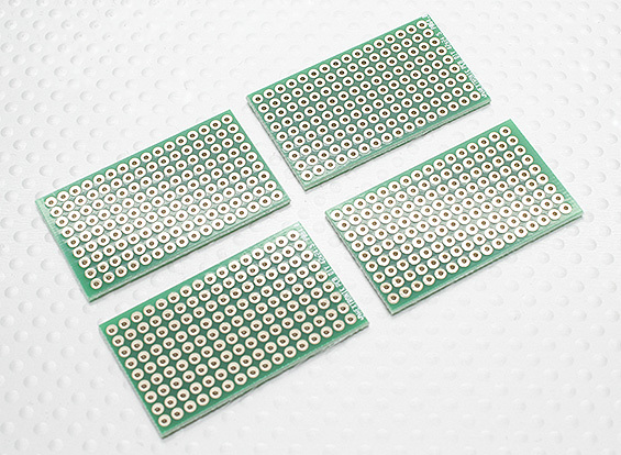
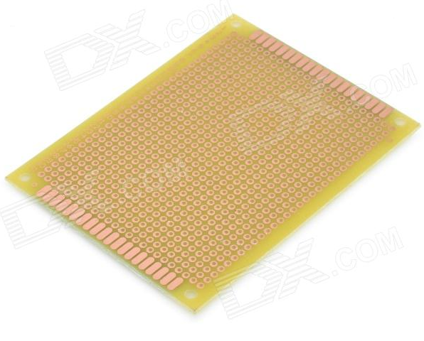
I ordered boards similar to these: on DX.COM or ebay
Pin contacts . The contact length is 2.54mm.
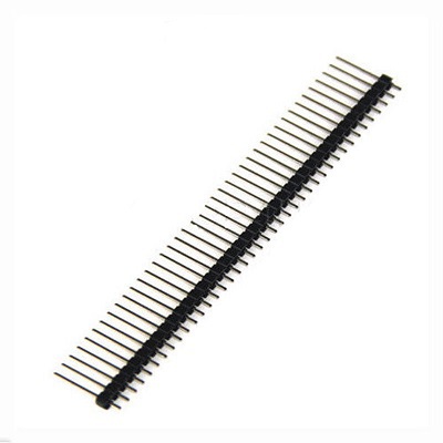
And so far I have decided to do this. Still, in fact, we need a tool for wrapping itself. It seems simple, it turned out to be not so cheap - about 600 rubles on ebay, and in Russia it is even more expensive. Therefore, from the entire set of possible diameters, I chose 30 AWG (0.25 mm) andtool for him . In my opinion, the most suitable diameter for building boards with DIP packages.
For aesthetes, there are connectors with gold pins ( 6 , 8 or 10 contacts). There is easier .
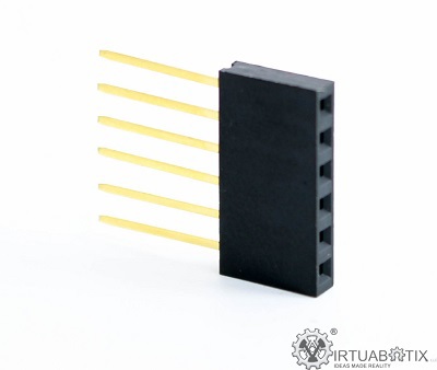
and sockets for microcircuits.

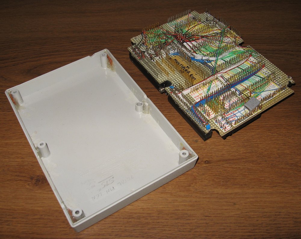
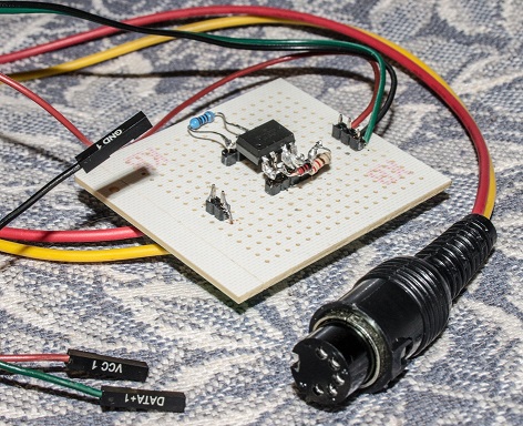
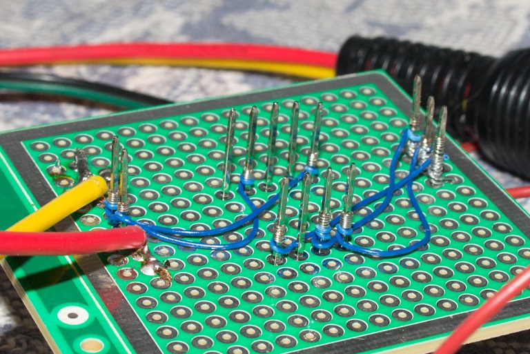
As part of my synthesizer project on FPGAs, I needed to make a MIDI-IN module. It essentially consists of an optocoupler and two mounted elements.

In principle, cheating here is an unnecessary complexity, but I wanted to test the technology. Here's what happened.
conclusions
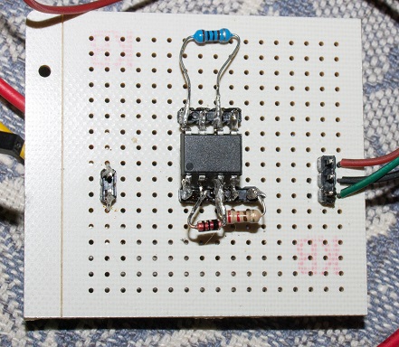
It was not possible to completely get rid of the soldering iron. In the process of creating the circuit, I made a mistake: I did not turn on the KD522 correctly (thanks to our for marking!), Which required a soldering. Another mistake was that I basically soldered the elements one on top of the other. If I soldered all the elements (microcircuit, resistor and diode) individually, to my pin contacts, then I would not need a soldering iron at all to correct errors. All connections would be made over the wire and corrections too.
However, in the process of working, I changed the circuit several times, until I realized why it did not work and appreciated the convenience of quick installation and dismantling of conductors. It was not always possible to wind it right the first time, but when the connection is correct, it can be seen right away. If the connection is not correct or a piece of wire is shorter than necessary, then removing the wire is a matter of a few seconds. In this case, without harm to compounds that have already been completed. Only moments when a soldering iron were required slowed down greatly. We can conclude that the technology is convenient and I will use it further!
I read a short video from me here:
List of sources used
1. http://en.wikipedia.org/wiki/Wire_wrap
2. http://ru.wikipedia.org/wiki/Montazh_nakrutkoy
3. http://wilsonminesco.com/6502primer/WireWrap.html
4. http: / /www.tecratools.com/pages/tecalert/wirewrap_guide.html
5. http://www.ibiblio.org/apollo/yaAGC.html - Virtual AGC
6. “Network Solutions Log / LAN”, No. 11, 2002 - Installation wrap- around
7. Solderless methods of indivisible connections: wrap
8. Neuron I9.66 - Personal computer compatible with IBM PC / XT . There is a wrap board .
9. FPGA VGA Resistor DAC - wire-wrap prototype design!
Other technologies:
10. Layout on the Veroboard stripboard and on simple stripboard and CAD for this