Another CI traffic light. This time attiny2313 and Node.js
Inspired by such a great idea as a traffic light reflecting the state of the build, I decided that our team needed the same. I did not want to be guided by the articles I read, since they use solutions that are too expensive for me. Therefore, armed with an idea, I outlined a very rough work plan for the team, and kept in my head simple principles that I want to follow.
Under the cut, a traffic light from color music and plastic bottles, a USB traffic light control module at attiny2313 for a dollar, as well as software for polling Jenkins and a USB module control on Node.js.
They decided to make a traffic light from the old color music, an even body and good glass - this is what you need. Visors were cut out of plastic bottles and painted black with the body. We got rid of the internal filling, because it worked from the mains voltage, and we need to redo it to 5v from USB.
Instead of lamps, I used LEDs that had previously been removed from the LED strip. For greater brightness, I decided to make assemblies of 4 LEDs connected in parallel and limited the current flowing through them with 100 ohm resistors, attiny2313 ports normally cope with a load of about 20 mA.
In order for the traffic lights to be fully illuminated, reflectors had to be made; for this, the upper part was cut off from plastic bottles and covered with aluminum tape from the inside. The glasses are mounted on the outside, so we had to cut the bottle so that the diameter of the cutoff circle was slightly larger than the diameter of the glass hole, so the resulting reflector could be inserted from the outside and clamped with glass, which eliminated the need to think of fixing reflectors.
I attached LED assemblies to the bottle caps with the help of M3 bolts and tubes with an inner diameter of 2 mm, this was done so that it was possible to adjust the distance for greater brightness.
I had two AVR microcontrollers available: a cheaper attiny13 with 1kB of memory and a little more expensive attiny2313 with 2kB of memory. In order for the device to work with the USB protocol, I was not going to complicate the scheme with additional USB modules, as this can be done directly on MK using the excellent V-USB library .
The minimum memory size required for this library is about 1.3kB - so the choice fell on attiny2313. The price of this microcontroller is 1-2 dollars, it will not be difficult to buy it either, since this is a very popular model.
The circuit diagram of the device is very simple, I will show my own for clarity, but I advise you to study possible options , since 3 variants of circuits are offered here, their advantages and disadvantages are described:

The main part of the circuit is the binding necessary for the computer to correctly determine the device as USB. It is necessary to change the voltage at the D + and D- USB contacts. The fact is that the voltage on the USB power contacts and the power of my circuit is 5V, but for signals on D + and D- the voltage should be 3.3V, for this they have zener diodes. The connection of the LEDs is so located only because I soldered without preliminary tracing, for the same reason I do not upload the board drawings. There is also a speaker on the diagram, it is necessary to play a melody fromof this article when the build falls.
The USB module can do just a little bit. Either shine with one LED, or blink one of them. The sound of the melody on the fallen build was not originally conceived, but was added to the already working device by updating the firmware.
After connecting the USB memory library to implement the necessary functionality, there was very little left, so I decided to simplify the logic on the MK side as much as possible and lay the responsibility for the correct operation of the device on the shoulders of computer software. So I came to the following form of the protocol: the device will receive messages consisting of a two-digit number, where the first digit is the port pin, and the second is a flag indicating whether the LED should light up or blink.
The melody starts only when the build falls, in general I have a hardcode there, I did not plan configurations for it.
I always write the firmware code in C in Eclipse, the gcc compiler from the WinAVR suite, upload the firmware with the USBasp programmer, which I bought for aliexpress for $ 4.5, and flash the fuzy with the Khazama program.
You should start with the firmware fuses. The circuit uses 12MHz quartz and for its use, fuses must be installed on quartz with a frequency greater than 8MHz (CKSEL = 1110). In addition, you must not forget to remove the frequency division by 8 (CKDIV8 = 1), if I am not mistaken, in attiny2313 the divider is set by default, I repeat, it needs to be disabled (set to one). Quartz at 12 MHz is not the only option; read about the options below at the bottom of this page . With such a small amount of memory, I should have chosen 16MHz, but I decided to stop at 12MHz.
First of all, you need to use the template code of the USB library. The usbdrv library folder should be in the project folder.
This code is required for the USB library to work. In addition to this code, you must also configure several parameters, for this you need to rename the usbconfig-prototype.h file in the usbdrv folder to usbconfig.h and tweak the necessary parameters, in my case it is:
It is worth noting here that it is possible to use any MK legs, but USB_CFG_DPLUS_BIT should point to a leg that supports external interrupts, since signals from the USB port will come along that leg.
The method that processes the received data looks like this:
This method works when the device receives data via USB, here I change the state variables depending on the received data. Further these variables will be used in the main program loop.
Reading data comes from the value of wValue, not the most correct option for transmitting data, but I found it quite appropriate in my case.
In my scheme, port D is used for the green traffic light, and port B is used for the yellow and red, so I had to declare a pointer to the port being used and add a condition for using port D if a signal came about a successful build. If for all signals to use different pins of one port, then this condition can be waived.
In addition to initializing the USB library, you must configure the ports to output, in my case, you can not configure the entire port D, because port D will be used by the USB library. I set the ones only on the pins, which I will use:
The main cycle starts with the USB required for operation:
Next is the logic responsible for the glow / blinking of one of the LEDs:
If the blink flag is not set, then just one is written in the required bit
Next is the unit responsible for playing the melody:
Only arrays of frequencies and length of notes were taken from the publication “Star Wars-style Musical Doorbell on Arduino” , as I already mentioned, there was very little memory left, so the melody playback process is integrated into the general loop so as not to disrupt the USB library. I decided not to make custom delays to set the desired frequency and length of the notes.
I will try to describe the process as detailed as possible. In order to apply the desired tone and duration to the speaker, it is necessary to switch the pin state with the frequency of the given note and do this for the duration of the specified note. For me, this process takes place in the main loop and runs in parallel with other tasks. To do this, I consider the duration of the current note and its frequency (the constants here depend on the delay at the end of the main cycle and were selected manually):
Until the duration is reached, I switch the state of the pin, but not for each tick, but provided that the current tick is divided without a remainder by frequency, that is, in this way I set the right frequency to achieve the desired key. Here I cheated a little, I admit the remainder after division in the code, I did this because some notes will sound the same because of the low accuracy of such calculations, which greatly spoils the melody, and the tolerance on the remainder makes such notes different.
After the circuit is assembled, and the microcontroller is flashed (how and what to look for, look up the Internet in your city), you can go to computer software.
There are plenty of options here. For working with DIY USB, a virtual COM port is very popular, the same Arduino creates a virtual COM port, which is quite simple to work with, you can work with it even with a regular bat file. But I really wanted to try working with USB, so my firmware was configured as a HID device, and the software should be able to work with USB.
After a little investigation, it turned out that one of the easiest options is the USB package for Node.js. In order to send a signal about a fallen build, just write 4 lines:
Here, the number 30 is sent by the wValue parameter to the device, otherwise it will supply voltage to the third pin of port B and start playing the melody.
Node.js is also no problem with Jenkins polling, we plug in the jenkins-api package and write:
In the console we will see: SUCCESS, FAILURE or null (during the build process).
To work with the USB module, you need to install the libUSB driver, this can be done either manually or use the zadig program , taken from the USB package page from the Installation item; for details - there, there are instructions for Linux and OSX.
Short video:
Full sources are here .
Thanks for attention.
Under the cut, a traffic light from color music and plastic bottles, a USB traffic light control module at attiny2313 for a dollar, as well as software for polling Jenkins and a USB module control on Node.js.
The project was divided into 3 parts
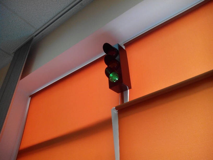
- Traffic light. We were not going to remove the traffic light from the intersection or try to buy it. We did not set ourselves the goal of hanging a real traffic light in the office, we are quite capable of making it from improvised materials.
- Electronics. I immediately discarded the Rasbery Pi and Arduino as redundant and expensive solutions. I needed access to the device via USB, I planned to use the USB power voltage as a power source for traffic lights, that is, to save the circuit from additional power.
- Software for working with USB on the computer side. Task: polling Jenkins current status of a specific build and sending the appropriate message via USB.
Traffic light
They decided to make a traffic light from the old color music, an even body and good glass - this is what you need. Visors were cut out of plastic bottles and painted black with the body. We got rid of the internal filling, because it worked from the mains voltage, and we need to redo it to 5v from USB.
Instead of lamps, I used LEDs that had previously been removed from the LED strip. For greater brightness, I decided to make assemblies of 4 LEDs connected in parallel and limited the current flowing through them with 100 ohm resistors, attiny2313 ports normally cope with a load of about 20 mA.
Picture
In order for the traffic lights to be fully illuminated, reflectors had to be made; for this, the upper part was cut off from plastic bottles and covered with aluminum tape from the inside. The glasses are mounted on the outside, so we had to cut the bottle so that the diameter of the cutoff circle was slightly larger than the diameter of the glass hole, so the resulting reflector could be inserted from the outside and clamped with glass, which eliminated the need to think of fixing reflectors.
Picture
I attached LED assemblies to the bottle caps with the help of M3 bolts and tubes with an inner diameter of 2 mm, this was done so that it was possible to adjust the distance for greater brightness.
Picture
More pictures

Electronics
I had two AVR microcontrollers available: a cheaper attiny13 with 1kB of memory and a little more expensive attiny2313 with 2kB of memory. In order for the device to work with the USB protocol, I was not going to complicate the scheme with additional USB modules, as this can be done directly on MK using the excellent V-USB library .
The minimum memory size required for this library is about 1.3kB - so the choice fell on attiny2313. The price of this microcontroller is 1-2 dollars, it will not be difficult to buy it either, since this is a very popular model.
Electronics circuit
The circuit diagram of the device is very simple, I will show my own for clarity, but I advise you to study possible options , since 3 variants of circuits are offered here, their advantages and disadvantages are described:
The main part of the circuit is the binding necessary for the computer to correctly determine the device as USB. It is necessary to change the voltage at the D + and D- USB contacts. The fact is that the voltage on the USB power contacts and the power of my circuit is 5V, but for signals on D + and D- the voltage should be 3.3V, for this they have zener diodes. The connection of the LEDs is so located only because I soldered without preliminary tracing, for the same reason I do not upload the board drawings. There is also a speaker on the diagram, it is necessary to play a melody fromof this article when the build falls.
Ready USB module

Principle of operation:
The USB module can do just a little bit. Either shine with one LED, or blink one of them. The sound of the melody on the fallen build was not originally conceived, but was added to the already working device by updating the firmware.
After connecting the USB memory library to implement the necessary functionality, there was very little left, so I decided to simplify the logic on the MK side as much as possible and lay the responsibility for the correct operation of the device on the shoulders of computer software. So I came to the following form of the protocol: the device will receive messages consisting of a two-digit number, where the first digit is the port pin, and the second is a flag indicating whether the LED should light up or blink.
The melody starts only when the build falls, in general I have a hardcode there, I did not plan configurations for it.
Firmware
I always write the firmware code in C in Eclipse, the gcc compiler from the WinAVR suite, upload the firmware with the USBasp programmer, which I bought for aliexpress for $ 4.5, and flash the fuzy with the Khazama program.
You should start with the firmware fuses. The circuit uses 12MHz quartz and for its use, fuses must be installed on quartz with a frequency greater than 8MHz (CKSEL = 1110). In addition, you must not forget to remove the frequency division by 8 (CKDIV8 = 1), if I am not mistaken, in attiny2313 the divider is set by default, I repeat, it needs to be disabled (set to one). Quartz at 12 MHz is not the only option; read about the options below at the bottom of this page . With such a small amount of memory, I should have chosen 16MHz, but I decided to stop at 12MHz.
First of all, you need to use the template code of the USB library. The usbdrv library folder should be in the project folder.
#include
#include
#include
#include
#include
#include "usbdrv/usbconfig.h"
#include "usbdrv/usbdrv.h"
PROGMEM const char usbHidReportDescriptor[22] = {
    0x06, 0x00, 0xff,
    0x09, 0x01,
    0xa1, 0x01,
    0x15, 0x00,
    0x26, 0xff, 0x00,
    0x75, 0x08,
    0x95, sizeof(uchar),
    0x09, 0x00,
    0xb2, 0x02, 0x01,
    0xc0
};
int main(void) {
    wdt_enable(WDTO_1S);
    usbInit();
    usbDeviceDisconnect();
    for(uchar i = 0; i<250; i++) { // wait 500 ms
        wdt_reset();
        _delay_ms(2);
    }
    usbDeviceConnect();
    sei();
    while(1) {
        wdt_reset();
        usbPoll();
        _delay_us(100);
    }
    return 0;
}
This code is required for the USB library to work. In addition to this code, you must also configure several parameters, for this you need to rename the usbconfig-prototype.h file in the usbdrv folder to usbconfig.h and tweak the necessary parameters, in my case it is:
#define USB_CFG_IOPORTNAME      D
#define USB_CFG_DMINUS_BIT      3
#define USB_CFG_DPLUS_BIT       2
#define USB_CFG_INTERFACE_CLASS     3
#define USB_CFG_HID_REPORT_DESCRIPTOR_LENGTH    22
It is worth noting here that it is possible to use any MK legs, but USB_CFG_DPLUS_BIT should point to a leg that supports external interrupts, since signals from the USB port will come along that leg.
The method that processes the received data looks like this:
#define PORT_D_THRESHOLD 40 // с какого числа начинать использование порта D
#define SERIALIZE_DEVIDER 10 // 51 / 10 = пин 5 и моргание 1
#define PLAY_ON_STATUS 30 // 30 - это горящий красный, начать воспроизведение мелодии
volatile uint8_t *blinkPort = &PORTB;
uint8_t pin;
uint8_t isBlink;
uint8_t play;
USB_PUBLIC uchar usbFunctionSetup(uchar data[8]) {
    usbRequest_t *rq = (void *)data; // cast data to correct type
    uint8_t status = rq->wValue.bytes[0]; //40/41 - 20/21 - 30/31 (возможные значения)
    // пишу 0 во все используемые мною пины очищая предыдущие состояния
    // чтобы избежать одновременного свечения нескольких светодиодов
    PORTD &=~ ((1 << PD5) | (1 << PD4));
    PORTB &=~ ((1 << PD2) | (1 << PD3));
    // если в сообщении пины 4 или 5, то работать будем с портом D
    // иначе с портом B
    if(status < PORT_D_THRESHOLD) {
        blinkPort = &PORTB;
    } else {
         blinkPort = &PORTD;
    }
    // десериализация
    isBlink = status % SERIALIZE_DEVIDER;
    pin = status / SERIALIZE_DEVIDER;
    play = status % PLAY_ON_STATUS == 0;
    return 0;
}
This method works when the device receives data via USB, here I change the state variables depending on the received data. Further these variables will be used in the main program loop.
Reading data comes from the value of wValue, not the most correct option for transmitting data, but I found it quite appropriate in my case.
In my scheme, port D is used for the green traffic light, and port B is used for the yellow and red, so I had to declare a pointer to the port being used and add a condition for using port D if a signal came about a successful build. If for all signals to use different pins of one port, then this condition can be waived.
Main () method:
In addition to initializing the USB library, you must configure the ports to output, in my case, you can not configure the entire port D, because port D will be used by the USB library. I set the ones only on the pins, which I will use:
DDRD = 0x30; //пины 5 и 4 порта D
DDRB = 0xC; //пины 2 и 3 порта B
Main loop:
The main cycle starts with the USB required for operation:
wdt_reset();
usbPoll();
Next is the logic responsible for the glow / blinking of one of the LEDs:
blinkDelay++;
if(blinkDelay > BLINK_DELAY) {
    blinkDelay = -BLINK_DELAY;
}
if(isBlink == 0) {
    *blinkPort |= (1 << pin);
} else {
    if(blinkDelay == 0) {
        *blinkPort ^= (1 << pin);
    }
}
If the blink flag is not set, then just one is written in the required bit
*blinkPort |= (1 << pin)*blinkPort ^= (1 << pin)Next is the unit responsible for playing the melody:
if(play == 1) {
    if(soundDelay < duration) {
        if(soundDelay % frequency <= FREQUECY_EDGE) {
            PORTD ^= (1 << PD5);
        }
    } else {
        soundDelay = 0;
        if(note == NOTES_COUNT) {
            note = 0;
            play = 0;
        }
        duration = pgm_read_word_near(durations + note) * DURATION_MULTIPLIER;
        frequency = FREQUENCY_DEV / pgm_read_word_near(frequences + note);
        note++;
    }
    soundDelay++;
}
Only arrays of frequencies and length of notes were taken from the publication “Star Wars-style Musical Doorbell on Arduino” , as I already mentioned, there was very little memory left, so the melody playback process is integrated into the general loop so as not to disrupt the USB library. I decided not to make custom delays to set the desired frequency and length of the notes.
I will try to describe the process as detailed as possible. In order to apply the desired tone and duration to the speaker, it is necessary to switch the pin state with the frequency of the given note and do this for the duration of the specified note. For me, this process takes place in the main loop and runs in parallel with other tasks. To do this, I consider the duration of the current note and its frequency (the constants here depend on the delay at the end of the main cycle and were selected manually):
duration = pgm_read_word_near(durations + note) * DURATION_MULTIPLIER;
frequency = FREQUENCY_DEV / pgm_read_word_near(frequences + note);
Until the duration is reached, I switch the state of the pin, but not for each tick, but provided that the current tick is divided without a remainder by frequency, that is, in this way I set the right frequency to achieve the desired key. Here I cheated a little, I admit the remainder after division in the code, I did this because some notes will sound the same because of the low accuracy of such calculations, which greatly spoils the melody, and the tolerance on the remainder makes such notes different.
Software
After the circuit is assembled, and the microcontroller is flashed (how and what to look for, look up the Internet in your city), you can go to computer software.
There are plenty of options here. For working with DIY USB, a virtual COM port is very popular, the same Arduino creates a virtual COM port, which is quite simple to work with, you can work with it even with a regular bat file. But I really wanted to try working with USB, so my firmware was configured as a HID device, and the software should be able to work with USB.
Writing to USB
After a little investigation, it turned out that one of the easiest options is the USB package for Node.js. In order to send a signal about a fallen build, just write 4 lines:
var usb = require('usb');
var device = usb.findByIds(5824, 1500); // VID и PID нашего устройства (эти стоят по умолчанию в V-USB конфиге)
device.open();
device.controlTransfer(usb.LIBUSB_REQUEST_TYPE_RESERVED, usb.LIBUSB_TRANSFER_TYPE_CONTROL, 30, 0, new Buffer(0), function(error, data){});
Here, the number 30 is sent by the wValue parameter to the device, otherwise it will supply voltage to the third pin of port B and start playing the melody.
Check Job's Job Status
Node.js is also no problem with Jenkins polling, we plug in the jenkins-api package and write:
var jenkinsapi = require('jenkins-api');
var JOB_NAME = 'JOB';
var JENKINS_URL = 'URL';
var jenkins = jenkinsapi.init(JENKINS_URL);
jenkins.last_build_info(JOB_NAME, function(err, data){
    console.log('Статус билда', data.result);
});
In the console we will see: SUCCESS, FAILURE or null (during the build process).
Driver for windows
To work with the USB module, you need to install the libUSB driver, this can be done either manually or use the zadig program , taken from the USB package page from the Installation item; for details - there, there are instructions for Linux and OSX.
Together
Short video:
Full sources are here .
Thanks for attention.