Cards from hexagons in Unity: bumps, rivers and roads
- Transfer
Parts 1-3: mesh, colors and height of cells
Parts 4-7: bumps, rivers and roads
Parts 8-11: water, objects of relief and walls of
Parts 12-15: preservation and loading, textures, distances
Parts 16-19: search paths, player squads, animations
Parts 20-23: fog of war, exploration map, procedural generation
Parts 24-27: water cycle, erosion, biomes, cylindrical map
Part 4: Irregularities
Table of contents
- Sample the noise texture.
- Move the vertices.
- Keep the cells flat.
- We subdivide the edges of the cells.
While our grid was a strict pattern of honeycombs. In this part, we will add bumps to make the map look more natural.
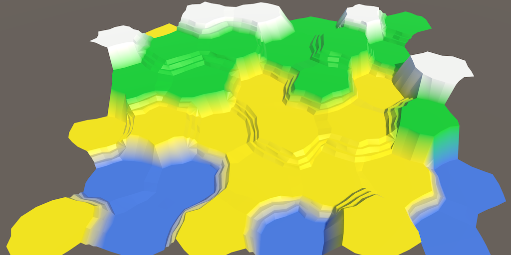
No more flat hexagons.
Noise
To add bumps, we need randomization, but not true randomness. We want everything to remain consistent when changing the map. Otherwise, when you make any changes, the objects will jump. That is, we need some form of reproducible pseudo-random noise.
A good candidate is Perlin's noise. It is reproducible at any point. When combining several frequencies, it also creates noise, which can vary greatly over long distances, but remains almost the same at short distances. This makes it possible to create relatively smooth distortion. Nearby points usually stay close together and are not scattered in opposite directions.
We can generate Perlin noise programmatically. In the tutorial NoiseI explain how to do this. But we can also sample from the pre-generated noise texture. The advantage of using a texture is that it is simpler and much faster than the calculation of the multi-frequency Perlin noise. Its disadvantage is that the texture takes up more memory and covers only a small area of noise. Therefore, it must be seamlessly connected and large enough so that the repetitions are not conspicuous.
Noise texture
We will use the texture, so you will not need to study the Noise tutorial . So we need a texture. Here she is:
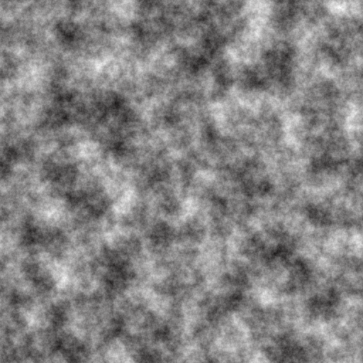
Seamlessly connected texture of Perlin noise.
The texture shown above contains Perlin's seamlessly interconnected multi-frequency noise. This is a grayscale image. Its average value is 0.5, and the extreme values tend to 0 and 1.
But wait, each point has only one value. If we need three-dimensional distortion, then we need at least three pseudo-random samples! Therefore, we need two more textures with different noise.
We can create them or store different noise values in each of the color channels. This will allow us to store up to four noise patterns in one texture. Here is the texture.
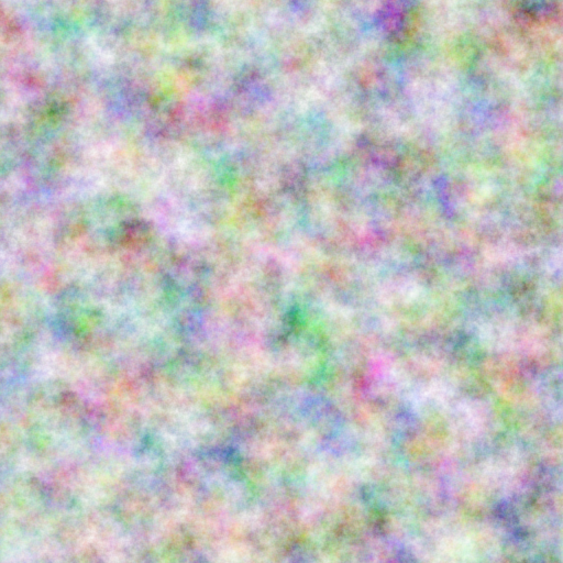
Four in one.
How to create such a texture?
Я использовал NumberFlow. Это созданный мной редактор процедурных текстур для Unity.
Download this texture and import it into the Unity project. Since we are going to sample the texture through the code, it should be readable. Switch Texture Type to Advanced and enable Read / Write Enabled . This will save the texture data in memory and can be accessed from C # code. Set the Format to Automatic Truecolor , otherwise it will not work. We don't want texture compression to destroy our noise pattern.
You can disable Generate Mip Maps , because we do not need them. Also enable Bypass sRGB Sampling. We will not need this, but it will be right. This parameter means that the texture does not contain color data in gamma space.
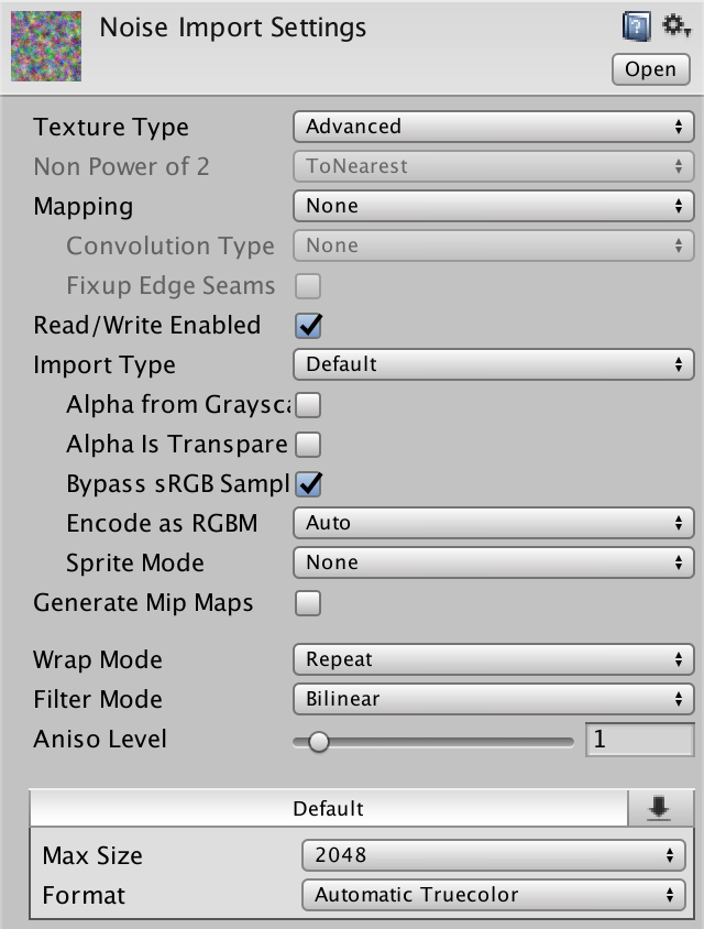
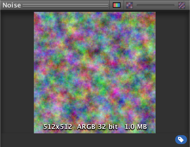
Imported noise texture.
When is sRGB sampling important?
Если бы мы хотели использовать текстуру в шейдере, то это имело бы значение. При использовании режиме Linear rendering сэмплирование текстуры автоматически преобразует цветовые данные из гаммы в линейное цветовое пространство. В случае нашей текстуры шума это приведёт к неверным результатам, поэтому нам этого не нужно.
Why do my texture import settings look different?
Их изменили после того, как был написан этот туториал. Нужно использовать настройки 2D-текстуры по умолчанию, sRGB (Color Texture) должно быть отключено, а для Compression должно быть задано значение None.
Noise sampling
Let's add noise sampling functionality
HexMetricsso that you can use it anywhere. This means that it HexMetricsmust contain a reference to the noise texture.publicstatic Texture2D noiseSource;Since this is not a component, we cannot assign a texture to it through the editor. Therefore, as an intermediary we use
HexGrid. Since it HexGridwill act first, it will be quite normal if we pass the texture at the beginning of its method Awake.public Texture2D noiseSource;
voidAwake () {
HexMetrics.noiseSource = noiseSource;
…
}However, this approach will not survive the replay in Play mode. Static variables are not serialized by the Unity engine. To solve this problem, reassign the texture in the event method
OnEnable. This method will be called after recompilation.voidOnEnable () {
HexMetrics.noiseSource = noiseSource;
}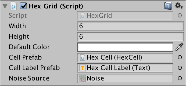
Assign a noise texture.
Now that you
HexMetricshave access to the texture, let's add a convenient noise sampling method to it. This method gains a position in the world and creates a 4D vector containing four noise samples.publicstatic Vector4 SampleNoise (Vector3 position) {
}Samples are created by texture sampling using bilinear filtering, in which the X and Z world coordinates were used as UV coordinates. Since our noise source is two-dimensional, we ignore the third coordinate of the world. If the noise source were three-dimensional, we would use the Y coordinate.
As a result, we get a color that can be converted into a 4D vector. Such a cast may be indirect, that is, we can return the color directly, not including explicitly
(Vector4).publicstatic Vector4 SampleNoise (Vector3 position) {
return noiseSource.GetPixelBilinear(position.x, position.z);
}How does bilinear filtering work?
Объяснения UV-координат и фильтрации текстур см. в туториале Rendering 2, Shader Fundamentals.
unitypackage
Moving vertices
We will distort our flat grid of cells, individually moving each of the vertices. To do this, let's add to the
HexMeshmethod Perturb. It takes the unplaced point and returns the displaced. To do this, it uses the unbiased point when sampling noise.Vector3 Perturb (Vector3 position) {
Vector4 sample = HexMetrics.SampleNoise(position);
}Let's just add samples of noise X, Y and Z directly with the corresponding coordinates of the point and use this as a result.
Vector3 Perturb (Vector3 position) {
		Vector4 sample = HexMetrics.SampleNoise(position);
		position.x += sample.x;
		position.y += sample.y;
		position.z += sample.z;
		return position;
	}
How do we quickly change
HexMeshto move all the vertices? By changing each vertex when adding to the list of vertices in the AddTriangleand methods AddQuad. Let's do it.voidAddTriangle (Vector3 v1, Vector3 v2, Vector3 v3) {
int vertexIndex = vertices.Count;
vertices.Add(Perturb(v1));
vertices.Add(Perturb(v2));
vertices.Add(Perturb(v3));
…
}
voidAddQuad (Vector3 v1, Vector3 v2, Vector3 v3, Vector3 v4) {
int vertexIndex = vertices.Count;
vertices.Add(Perturb(v1));
vertices.Add(Perturb(v2));
vertices.Add(Perturb(v3));
vertices.Add(Perturb(v4));
…
}Will quadrangles remain flat after moving their vertices?
Скорее всего нет. Они состоят из двух треугольников, которые больше не будут лежать в одной плоскости. Однако поскольку эти треугольники имеют две общих вершины, нормали этих вершин будут сглажены. Это значит, что у нас не будет резких переходов между двумя треугольниками. Если искажение не слишком велико, то мы по-прежнему будем воспринимать четырёхугольники плоскими.
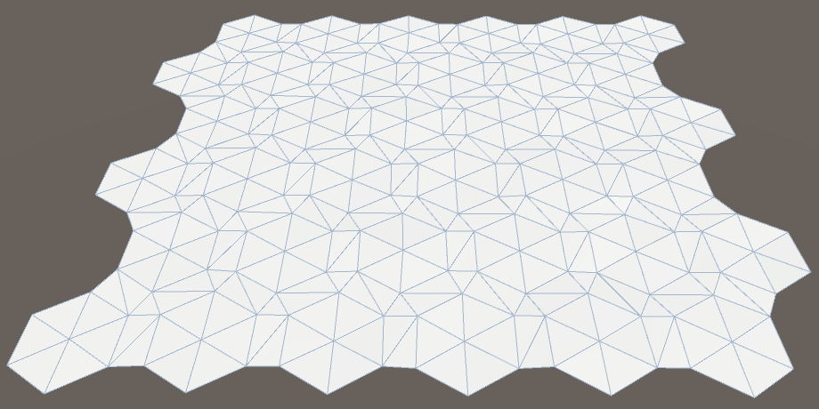
Vertices either moved or not.
While the changes are not very noticeable, only the labels of the cells have disappeared. This happened because we added noise to samples, and they are always positive. Therefore, as a result, all the triangles have risen above their marks, closing them. We need to center the changes so that they occur in both directions. Change the interval of the noise sample from 0–1 to −1–1.
Vector3 Perturb (Vector3 position) {
		Vector4 sample = HexMetrics.SampleNoise(position);
		position.x += sample.x * 2f - 1f;
		position.y += sample.y * 2f - 1f;
		position.z += sample.z * 2f - 1f;
		return position;
	}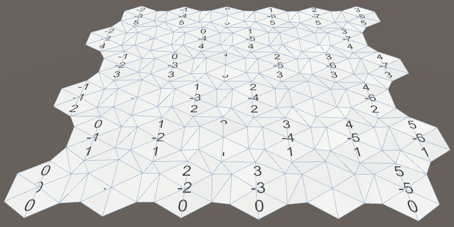
Centered displacement.
The magnitude (force) of movement
Now it is obvious that we have distorted the grid, but the effect is barely noticeable. The change in each dimension is no more than 1 unit. That is, the theoretical maximum displacement is √3 ≈ 1.73 units, which will occur extremely rarely, if at all. Since the outer radius of the cells is 10 units, the displacements are relatively small.
The solution is to add
HexMetricsforce to the parameter so that the displacements can be scaled. Let's try using force 5. At the same time, the theoretical maximum offset will be √75 ≈ 8.66 units, which is much more noticeable.publicconstfloat cellPerturbStrength = 5f;We apply force by multiplying it into samples in
HexMesh.Perturb.Vector3 Perturb (Vector3 position) {
Vector4 sample = HexMetrics.SampleNoise(position);
position.x += (sample.x * 2f - 1f) * HexMetrics.cellPerturbStrength;
position.y += (sample.y * 2f - 1f) * HexMetrics.cellPerturbStrength;
position.z += (sample.z * 2f - 1f) * HexMetrics.cellPerturbStrength;
return position;
}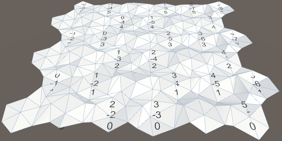
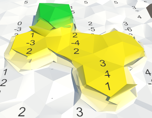
Increased strength.
Noise scale
Although the grid looks good before the change, things can go wrong after the steps appear. Their tops can be distorted in unpredictably different directions, creating chaos. When using Perlin noise, this should not happen.
The problem arises because we directly use the coordinates of the world to sample the noise. Because of this, the texture is hidden through each unit, and the cells are much larger than this value. In fact, the texture is sampled at arbitrary points, destroying the integrity it has.
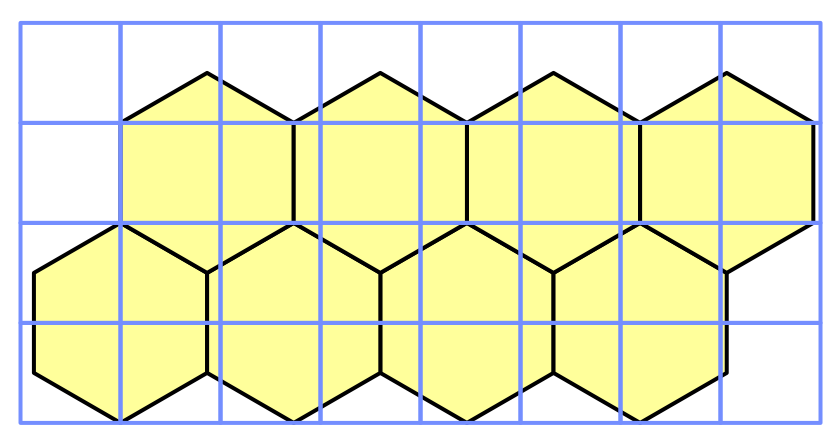
Grid rows 10 by 10 overlap cells.
We will have to scale the noise sampling so that the texture covers a much larger area. Let's add this scale to
HexMetricsand assign it a value of 0.003, and then scale the coordinates of the samples by this factor.publicconstfloat noiseScale = 0.003f;
publicstatic Vector4 SampleNoise (Vector3 position) {
return noiseSource.GetPixelBilinear(
position.x * noiseScale,
position.z * noiseScale
);
}Suddenly, it turns out that our texture covers 333 & frac13; square units, and its local integrity becomes apparent.
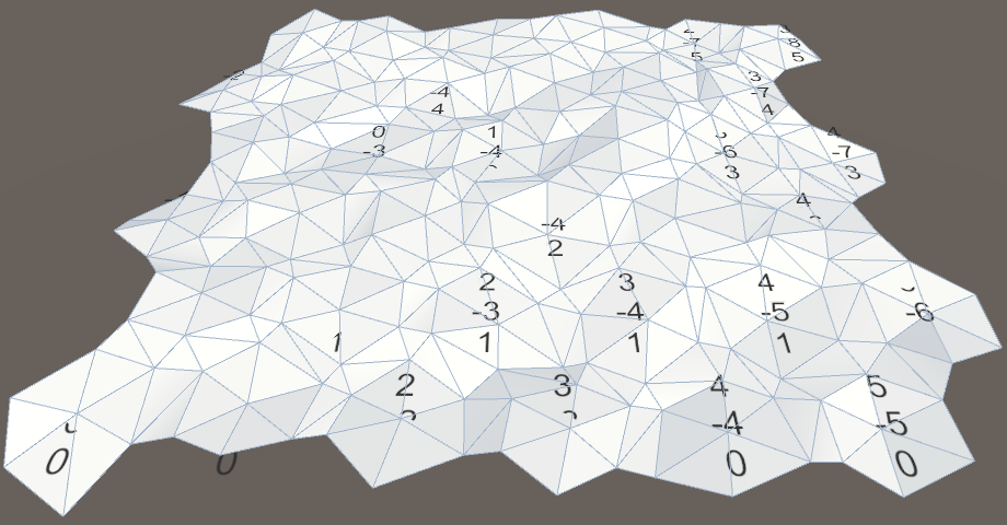
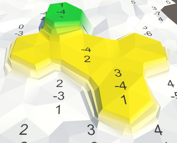
Scaled noise.
In addition, the new scale increases the distance between the noise junctions. In fact, since the cells have an inner diameter of 10√3 units, it will never exactly hide in dimension X. However, due to the local integrity of the noise, on a larger scale we will still be able to recognize repeating patterns, approximately every 20 cells, even if the details do not match. But they will be obvious only on the map without other features.
unitypackage
Align Cell Centers
Moving all the vertices gives the map a more natural look, but several problems arise. Since the cells are now uneven, their labels intersect with the mesh. And in the joints of the ledges with cliffs cracks occur. We will leave the cracks for later, and now we will concentrate on the surfaces of the cells.
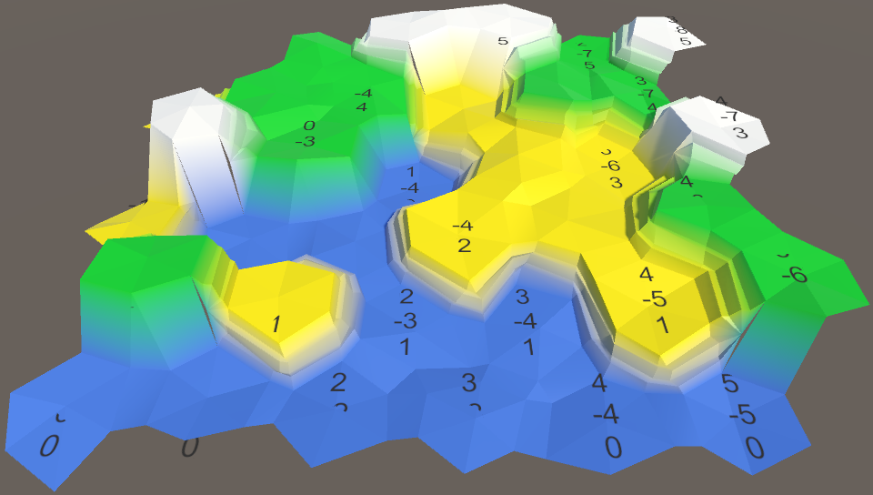
The map has become less strict, but more problems have appeared.
The easiest way to solve the intersection problem is to make the centers of the cells flat. Let's just not change the Y coordinate in
HexMesh.Perturb.Vector3 Perturb (Vector3 position) {
Vector4 sample = HexMetrics.SampleNoise(position);
position.x += (sample.x * 2f - 1f) * HexMetrics.cellPerturbStrength;
// position.y += (sample.y * 2f - 1f) * HexMetrics.cellPerturbStrength;
position.z += (sample.z * 2f - 1f) * HexMetrics.cellPerturbStrength;
return position;
}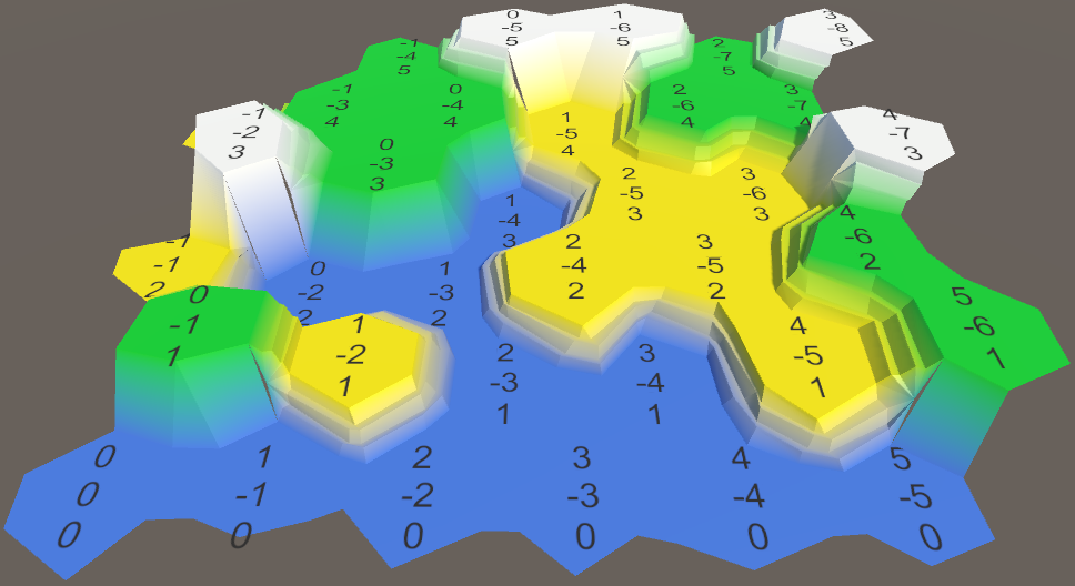
Aligned cells.
With this change, all vertical positions will remain unchanged, both at the centers of the cells and at the steps of the ledges. It should be noted that this reduces the maximum displacement to √50 ≈ 7.07 only in the XZ plane.
This is a nice change, because it simplifies the identification of individual cells and prevents the ledges from becoming too chaotic. But it would still be nice to add a small vertical movement.
Moving cell height
Instead of applying vertical movement to each vertex, we can apply it to the cell. In this case, each cell will remain flat, but the variation between the cells will still remain. It would also be logical to use another scale for moving the height, so we will add it to
HexMetrics. The strength of 1.5 units creates a small variation, approximately equal to the height of one step of the ledge.publicconstfloat elevationPerturbStrength = 1.5f;Change the property
HexCell.Elevationso that it applies this move to the vertical position of the cell.publicint Elevation {
get {
return elevation;
}
set {
elevation = value;
Vector3 position = transform.localPosition;
position.y = value * HexMetrics.elevationStep;
position.y +=
(HexMetrics.SampleNoise(position).y * 2f - 1f) *
HexMetrics.elevationPerturbStrength;
transform.localPosition = position;
Vector3 uiPosition = uiRect.localPosition;
uiPosition.z = -position.y;
uiRect.localPosition = uiPosition;
}
}In order for the movement to be applied immediately, we need to explicitly set the height of each cell in
HexGrid.CreateCell. Otherwise, the mesh will initially be flat. We do this at the end, after creating the UI.voidCreateCell (int x, int z, int i) {
…
cell.Elevation = 0;
}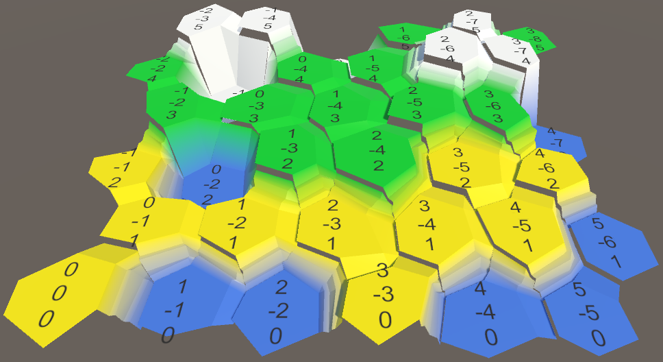
Moved heights with cracks.
Use the same heights
Many cracks appeared in the mesh, because we do not use the same cell heights during the mesh triangulation. Let's add a
HexCellproperty to get its position so that you can use it anywhere.public Vector3 Position {
get {
return transform.localPosition;
}
}Now we can use this property in
HexMesh.Triangulateto determine the center of the cell.voidTriangulate (HexDirection direction, HexCell cell) {
Vector3 center = cell.Position;
…
}And we can use it in
TriangulateConnectiondetermining the vertical positions of neighboring cells.voidTriangulateConnection (
HexDirection direction, HexCell cell, Vector3 v1, Vector3 v2
) {
…
Vector3 bridge = HexMetrics.GetBridge(direction);
Vector3 v3 = v1 + bridge;
Vector3 v4 = v2 + bridge;
v3.y = v4.y = neighbor.Position.y;
…
HexCell nextNeighbor = cell.GetNeighbor(direction.Next());
if (direction <= HexDirection.E && nextNeighbor != null) {
Vector3 v5 = v2 + HexMetrics.GetBridge(direction.Next());
v5.y = nextNeighbor.Position.y;
…
}
}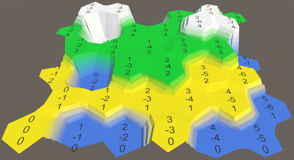
Consistent use of cell heights.
unitypackage
Cell Edge Division
Although cells have beautiful variability, they still look like obvious hexagons. This in itself is not a problem, but we can improve their appearance.
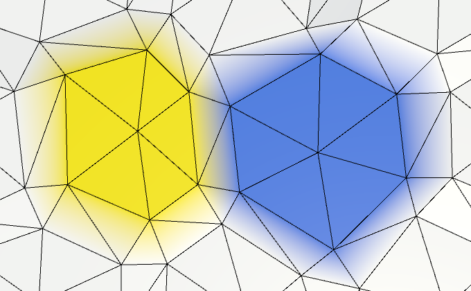
Clearly visible hexagonal cells.
If we had more vertices, then there would be more local variation. So let's split each edge of a cell into two parts, adding the top of the edge in the middle between each pair of corners. This means that you
HexMesh.Triangulatemust add not one, but two triangles.voidTriangulate (HexDirection direction, HexCell cell) {
Vector3 center = cell.Position;
Vector3 v1 = center + HexMetrics.GetFirstSolidCorner(direction);
Vector3 v2 = center + HexMetrics.GetSecondSolidCorner(direction);
Vector3 e1 = Vector3.Lerp(v1, v2, 0.5f);
AddTriangle(center, v1, e1);
AddTriangleColor(cell.color);
AddTriangle(center, e1, v2);
AddTriangleColor(cell.color);
if (direction <= HexDirection.SE) {
TriangulateConnection(direction, cell, v1, v2);
}
}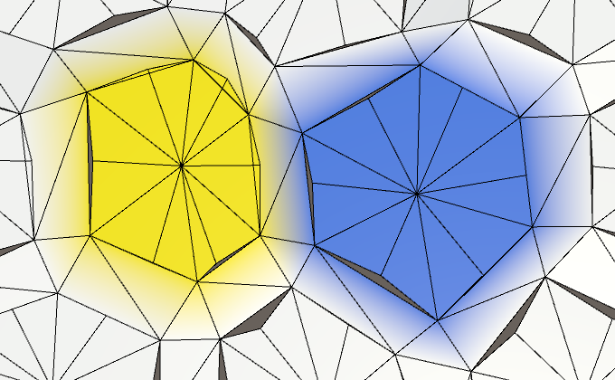
Twelve sides instead of six.
Doubling vertices and triangles adds more variation to the edges of the cell. Let's make them even more irregular by tripling the number of vertices.
		Vector3 e1 = Vector3.Lerp(v1, v2, 1f / 3f);
		Vector3 e2 = Vector3.Lerp(v1, v2, 2f / 3f);
		AddTriangle(center, v1, e1);
		AddTriangleColor(cell.color);
		AddTriangle(center, e1, e2);
		AddTriangleColor(cell.color);
		AddTriangle(center, e2, v2);
		AddTriangleColor(cell.color);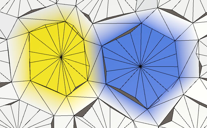
18 sides.
Rib connection division
Of course, we also need to subdivide rib connections. Therefore, pass the new vertices of the edges in
TriangulateConnection.if (direction <= HexDirection.SE) {
TriangulateConnection(direction, cell, v1, e1, e2, v2);
}Add the appropriate parameters in
TriangulateConnection, so that it can work with additional vertices.voidTriangulateConnection (
HexDirection direction, HexCell cell,
Vector3 v1, Vector3 e1, Vector3 e2, Vector3 v2
) {
…
}We also need to compute the additional vertices of the edges for neighboring cells. We can calculate them after connecting the bridge to the other side.
		Vector3 bridge = HexMetrics.GetBridge(direction);
		Vector3 v3 = v1 + bridge;
		Vector3 v4 = v2 + bridge;
		v3.y = v4.y = neighbor.Position.y;
		Vector3 e3 = Vector3.Lerp(v3, v4, 1f / 3f);
		Vector3 e4 = Vector3.Lerp(v3, v4, 2f / 3f);
Next, we need to change the edge triangulation. While we ignore the slopes with ledges, we simply add three instead of one quad.
if (cell.GetEdgeType(direction) == HexEdgeType.Slope) {
			TriangulateEdgeTerraces(v1, v2, cell, v3, v4, neighbor);
		}
		else {
			AddQuad(v1, e1, v3, e3);
			AddQuadColor(cell.color, neighbor.color);
			AddQuad(e1, e2, e3, e4);
			AddQuadColor(cell.color, neighbor.color);
			AddQuad(e2, v2, e4, v4);
			AddQuadColor(cell.color, neighbor.color);
		}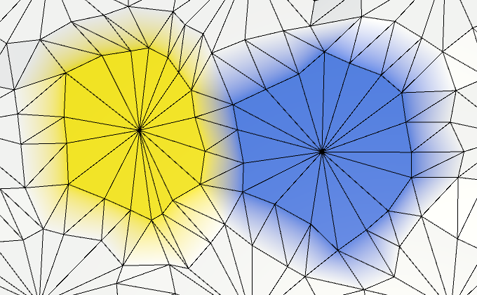
Subdivided connections.
Edge vertex union
Since we now need four vertices to describe the edge, it would be logical to combine them into a set. This is more convenient than working with four independent vertices. Create a simple structure for this
EdgeVertices. It should contain four vertices, going in clockwise order along the edge of the cell.using UnityEngine;
publicstruct EdgeVertices {
public Vector3 v1, v2, v3, v4;
}Shouldn't they be serializable?
Мы будем использовать эту структуру только при триангуляции. На этом этапе нам не нужно хранить вершины рёбер, поэтому сериализуемыми их делать необязательно.
Add a convenient constructor method to it, which will calculate the intermediate points of the edge.
publicEdgeVertices (Vector3 corner1, Vector3 corner2) {
		v1 = corner1;
		v2 = Vector3.Lerp(corner1, corner2, 1f / 3f);
		v3 = Vector3.Lerp(corner1, corner2, 2f / 3f);
		v4 = corner2;
	}
Now we can add
HexMeshtriangulation to a separate method to create a fan of triangles between the center of the cell and one of its edges.voidTriangulateEdgeFan (Vector3 center, EdgeVertices edge, Color color) {
AddTriangle(center, edge.v1, edge.v2);
AddTriangleColor(color);
AddTriangle(center, edge.v2, edge.v3);
AddTriangleColor(color);
AddTriangle(center, edge.v3, edge.v4);
AddTriangleColor(color);
}And a method for triangulating a strip of quadrilaterals between two edges.
voidTriangulateEdgeStrip (
		EdgeVertices e1, Color c1,
		EdgeVertices e2, Color c2
	) {
		AddQuad(e1.v1, e1.v2, e2.v1, e2.v2);
		AddQuadColor(c1, c2);
		AddQuad(e1.v2, e1.v3, e2.v2, e2.v3);
		AddQuadColor(c1, c2);
		AddQuad(e1.v3, e1.v4, e2.v3, e2.v4);
		AddQuadColor(c1, c2);
	}
This will allow us to simplify the method
Triangulate.voidTriangulate (HexDirection direction, HexCell cell) {
Vector3 center = cell.Position;
EdgeVertices e = new EdgeVertices(
center + HexMetrics.GetFirstSolidCorner(direction),
center + HexMetrics.GetSecondSolidCorner(direction)
);
TriangulateEdgeFan(center, e, cell.color);
if (direction <= HexDirection.SE) {
TriangulateConnection(direction, cell, e);
}
}Let's go to
TriangulateConnection. Now we can use TriangulateEdgeStrip, but other changes need to be made. Where we used before v1, we need to use e1.v1. Similarly, v2becomes e1.v4, v3becomes e2.v1, and v4becomes e2.v4.voidTriangulateConnection (
HexDirection direction, HexCell cell, EdgeVertices e1
) {
HexCell neighbor = cell.GetNeighbor(direction);
if (neighbor == null) {
return;
}
Vector3 bridge = HexMetrics.GetBridge(direction);
bridge.y = neighbor.Position.y - cell.Position.y;
EdgeVertices e2 = new EdgeVertices(
e1.v1 + bridge,
e1.v4 + bridge
);
if (cell.GetEdgeType(direction) == HexEdgeType.Slope) {
TriangulateEdgeTerraces(e1.v1, e1.v4, cell, e2.v1, e2.v4, neighbor);
}
else {
TriangulateEdgeStrip(e1, cell.color, e2, neighbor.color);
}
HexCell nextNeighbor = cell.GetNeighbor(direction.Next());
if (direction <= HexDirection.E && nextNeighbor != null) {
Vector3 v5 = e1.v4 + HexMetrics.GetBridge(direction.Next());
v5.y = nextNeighbor.Position.y;
if (cell.Elevation <= neighbor.Elevation) {
if (cell.Elevation <= nextNeighbor.Elevation) {
TriangulateCorner(
e1.v4, cell, e2.v4, neighbor, v5, nextNeighbor
);
}
else {
TriangulateCorner(
v5, nextNeighbor, e1.v4, cell, e2.v4, neighbor
);
}
}
elseif (neighbor.Elevation <= nextNeighbor.Elevation) {
TriangulateCorner(
e2.v4, neighbor, v5, nextNeighbor, e1.v4, cell
);
}
else {
TriangulateCorner(
v5, nextNeighbor, e1.v4, cell, e2.v4, neighbor
);
}
}Ledge division
We need to subdivide and ledges. Therefore, we pass the edges
TriangulateEdgeTerraces.if (cell.GetEdgeType(direction) == HexEdgeType.Slope) {
TriangulateEdgeTerraces(e1, cell, e2, neighbor);
}Now we have to change it
TriangulateEdgeTerracesso that it interpolates between edges, and not between pairs of vertices. Let's assume that you EdgeVerticeshave a convenient static method for this. This will allow us to simplify TriangulateEdgeTerraces, and not complicate it.voidTriangulateEdgeTerraces (
EdgeVertices begin, HexCell beginCell,
EdgeVertices end, HexCell endCell
) {
EdgeVertices e2 = EdgeVertices.TerraceLerp(begin, end, 1);
Color c2 = HexMetrics.TerraceLerp(beginCell.color, endCell.color, 1);
TriangulateEdgeStrip(begin, beginCell.color, e2, c2);
for (int i = 2; i < HexMetrics.terraceSteps; i++) {
EdgeVertices e1 = e2;
Color c1 = c2;
e2 = EdgeVertices.TerraceLerp(begin, end, i);
c2 = HexMetrics.TerraceLerp(beginCell.color, endCell.color, i);
TriangulateEdgeStrip(e1, c1, e2, c2);
}
TriangulateEdgeStrip(e2, c2, end, endCell.color);
}The method
EdgeVertices.TerraceLerpsimply interpolates the ledges between all four pairs of vertices of two edges.publicstatic EdgeVertices TerraceLerp (
EdgeVertices a, EdgeVertices b, int step)
{
EdgeVertices result;
result.v1 = HexMetrics.TerraceLerp(a.v1, b.v1, step);
result.v2 = HexMetrics.TerraceLerp(a.v2, b.v2, step);
result.v3 = HexMetrics.TerraceLerp(a.v3, b.v3, step);
result.v4 = HexMetrics.TerraceLerp(a.v4, b.v4, step);
return result;
}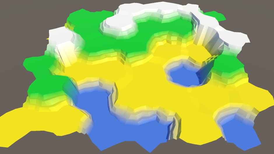
Subdivided ledges.
unitypackage
Reconnect the cliffs and ledges
While we ignored the cracks in the joints of cliffs and ledges. It is time to solve this problem. Let's first consider the cases of "precipice-slope-slope" (OSS) and "slope-precipice-slope" (SOS).
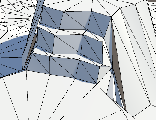
Holes in meshe.
The problem arises because the vertices of the borders have moved. This means that now they do not lie flat on the side of the cliff, which leads to a crack. Sometimes these holes are invisible, and sometimes striking.
The solution is to not move the top of the border. This means that we need to control whether the point will be moved. The easiest way is to create an alternative
AddTrianglethat does not move the vertices at all.voidAddTriangleUnperturbed (Vector3 v1, Vector3 v2, Vector3 v3) {
int vertexIndex = vertices.Count;
vertices.Add(v1);
vertices.Add(v2);
vertices.Add(v3);
triangles.Add(vertexIndex);
triangles.Add(vertexIndex + 1);
triangles.Add(vertexIndex + 2);
}Change it
TriangulateBoundaryTriangleso that it uses this method. This means that it will have to explicitly move all the vertices, except for the boundary ones.voidTriangulateBoundaryTriangle (
Vector3 begin, HexCell beginCell,
Vector3 left, HexCell leftCell,
Vector3 boundary, Color boundaryColor
) {
Vector3 v2 = HexMetrics.TerraceLerp(begin, left, 1);
Color c2 = HexMetrics.TerraceLerp(beginCell.color, leftCell.color, 1);
AddTriangleUnperturbed(Perturb(begin), Perturb(v2), boundary);
AddTriangleColor(beginCell.color, c2, boundaryColor);
for (int i = 2; i < HexMetrics.terraceSteps; i++) {
Vector3 v1 = v2;
Color c1 = c2;
v2 = HexMetrics.TerraceLerp(begin, left, i);
c2 = HexMetrics.TerraceLerp(beginCell.color, leftCell.color, i);
AddTriangleUnperturbed(Perturb(v1), Perturb(v2), boundary);
AddTriangleColor(c1, c2, boundaryColor);
}
AddTriangleUnperturbed(Perturb(v2), Perturb(left), boundary);
AddTriangleColor(c2, leftCell.color, boundaryColor);
}It is worth noting the following: since we do not use
v2to get some other point, we can move it immediately. This is a simple optimization and it reduces the amount of code, so let's add it.voidTriangulateBoundaryTriangle (
Vector3 begin, HexCell beginCell,
Vector3 left, HexCell leftCell,
Vector3 boundary, Color boundaryColor
) {
Vector3 v2 = Perturb(HexMetrics.TerraceLerp(begin, left, 1));
Color c2 = HexMetrics.TerraceLerp(beginCell.color, leftCell.color, 1);
AddTriangleUnperturbed(Perturb(begin), v2, boundary);
AddTriangleColor(beginCell.color, c2, boundaryColor);
for (int i = 2; i < HexMetrics.terraceSteps; i++) {
Vector3 v1 = v2;
Color c1 = c2;
v2 = Perturb(HexMetrics.TerraceLerp(begin, left, i));
c2 = HexMetrics.TerraceLerp(beginCell.color, leftCell.color, i);
AddTriangleUnperturbed(v1, v2, boundary);
AddTriangleColor(c1, c2, boundaryColor);
}
AddTriangleUnperturbed(v2, Perturb(left), boundary);
AddTriangleColor(c2, leftCell.color, boundaryColor);
}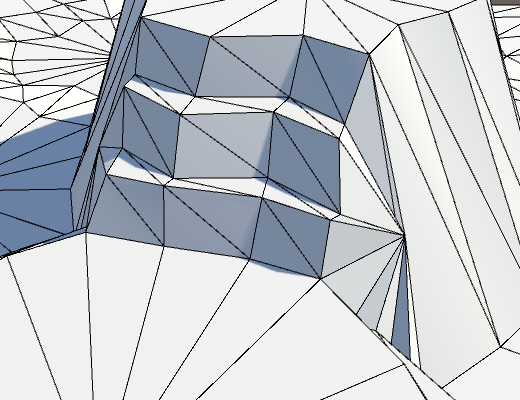
Unmoved boundaries.
It looks better, but we have not finished yet. Inside the method, the
TriangulateCornerTerracesCliffboundary point is found by interpolation between the left and right points. However, these points have not yet been moved. To match the boundary point to the resulting break, we need to interpolate between the displaced points. Vector3 boundary = Vector3.Lerp(Perturb(begin), Perturb(right), b);The same is true for the method
TriangulateCornerCliffTerraces. Vector3 boundary = Vector3.Lerp(Perturb(begin), Perturb(left), b);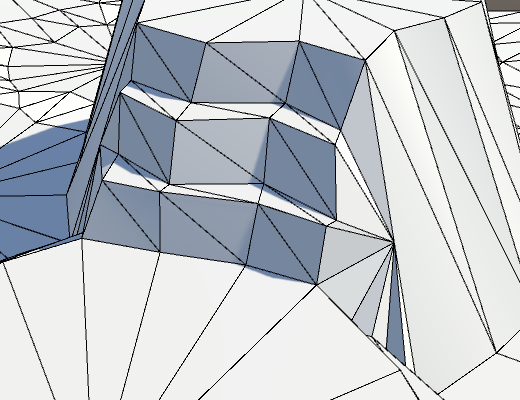
Holes are gone.
Double cliffs and slope
In all the remaining problem cases, there are two cliffs and one slope.

A big hole because of a single triangle.
This problem is eliminated by manually moving a single triangle in the block
elseat the end TriangulateCornerTerracesCliff.else {
AddTriangleUnperturbed(Perturb(left), Perturb(right), boundary);
AddTriangleColor(leftCell.color, rightCell.color, boundaryColor);
}The same applies to
TriangulateCornerCliffTerraces.else {
AddTriangleUnperturbed(Perturb(left), Perturb(right), boundary);
AddTriangleColor(leftCell.color, rightCell.color, boundaryColor);
}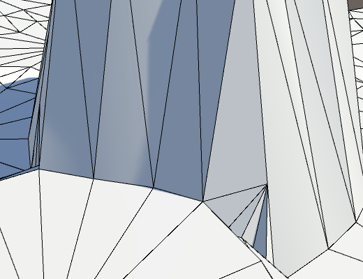
Get rid of the last cracks.
unitypackage
Revision
Now we have a completely correct distorted mesh. Its appearance depends on the specific noise, its scale and the forces of distortion. In our case, the distortion may seem too strong. Although this irregularity looks beautiful, we do not want the cells to deviate too far from a flat grid. In the end, we still use it to define a variable cell. And if the cell size will vary too much, then it will be more difficult for us to place the content in them.
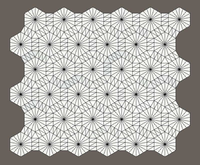
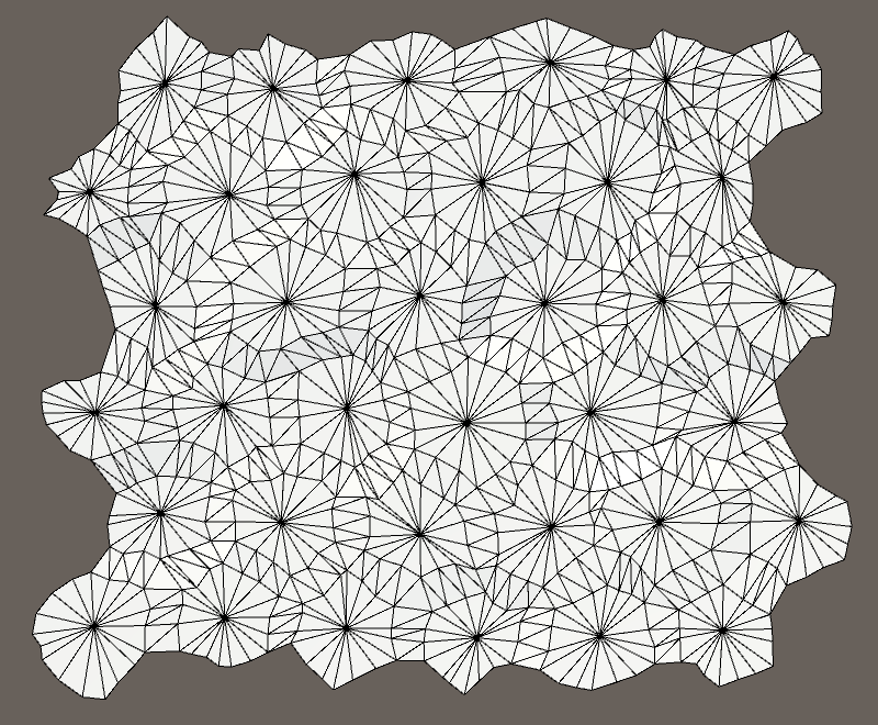
Undistorted and distorted mesh.
It seems that the power of 5 to distort the cells is too great.
Cell distortion from 0 to 5.
Let's reduce it to 4 in order to increase the convenience of the grid without making it too correct. This ensures that the maximum offset in XZ will be √32 ≈ 5.66 units.
publicconstfloat cellPerturbStrength = 4f;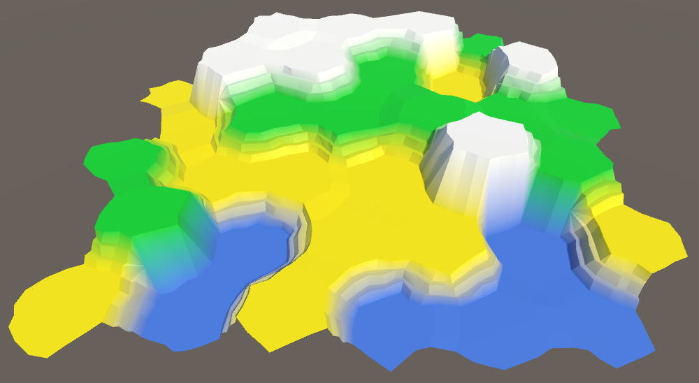
Cell distortion force 4.
Another value that can be changed is the coefficient of wholeness. If we increase it, the flat centers of the cells will become larger, that is, there will be more space for future content. Of course, with this they will become more hexagonal.
Integrity factor from 0.75 to 0.95.
A small increase in the coefficient of integrity up to 0.8 will slightly simplify our life in the future.
publicconstfloat solidFactor = 0.8f;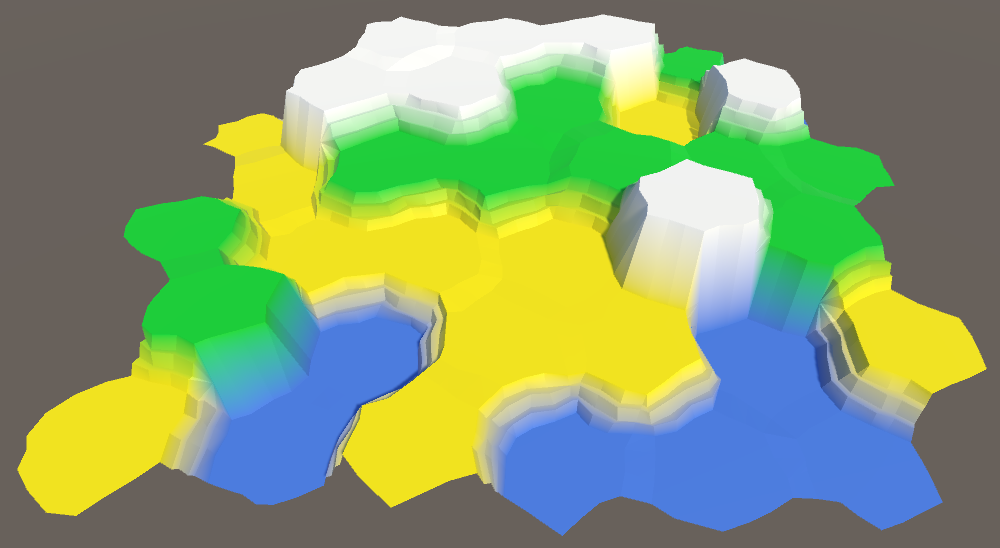
Integrity coefficient 0.8.
Finally, you can see that the differences between the levels of heights are too sharp. This is useful when you need to make sure that the mesh is correctly generated, but we are already done with it. Let's reduce it to 1 unit per step of the ledge, that is, to 3.
publicconstfloat elevationStep = 3f;
The pitch is reduced to 3.
Also we can change the height distortion force. But now it has a value of 1.5, which is equal to half the height step, which suits us.
Small steps of heights make it more logical to use all seven levels of height. This increases the variability of the map.
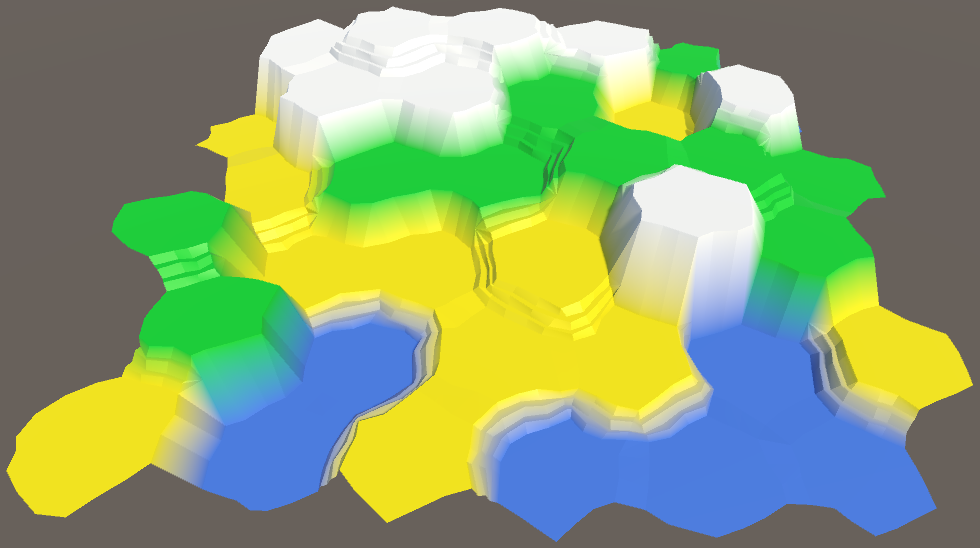
Use seven levels of heights.
unitypackage
Part 5: Larger Cards
- Divide the grid into fragments.
- We control the camera.
- We color the colors and heights separately.
- Use the enlarged brush cells.
So far we have been working with a very small map. It is time to increase it.
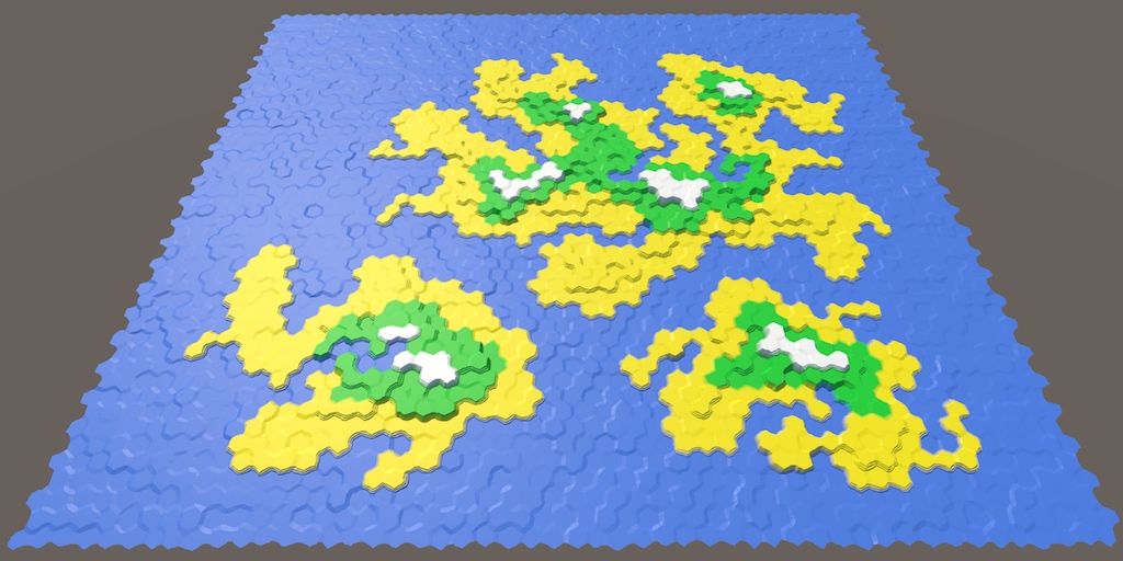
It's time to zoom.
Grid Fragments
We cannot make the grid too large, because we will rest on the limits of what can fit in one mesh. How to solve this problem? Use multiple meshes. For this we need to divide our grid into several fragments. We use rectangular fragments of constant size.
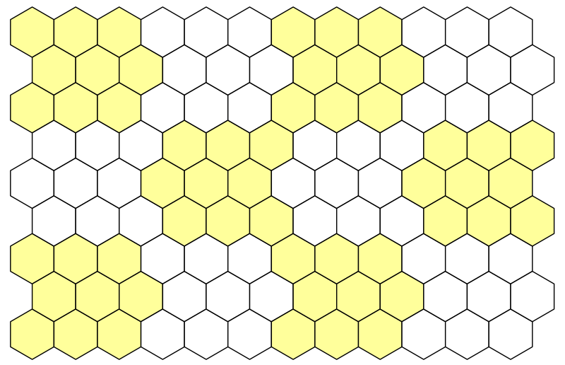
Breaking the grid into 3 by 3 segments.
Let's use blocks 5 by 5, that is, 25 cells per fragment. We define them in
HexMetrics.publicconstint chunkSizeX = 5, chunkSizeZ = 5;What fragment size can be considered appropriate?
Сложно сказать. При использовании больших фрагментов мешей нужно меньше, но их размер будет больше. При этом снижается количество вызовов отрисовки. Но чем меньше фрагменты по размерам, тем лучше они отсекаются пирамидой видимости (frustum culling), что приводит к отрисовке меньшего количества треугольников. Логичнее будет просто выбрать размер и при необходимости подстроить его в дальнейшем.
Now we can not use any size for the grid, it must be a multiple of the fragment size. Therefore, let's change it
HexGridso that it sets its size not in separate cells, but in fragments. Set the default size to 4 for 3 fragments, that is, a total of 12 fragments or 300 cells. So we get a convenient test card.publicint chunkCountX = 4, chunkCountZ = 3;We still use
widthand height, but now they have to become private. And rename them to cellCountXand cellCountZ. Use the editor to rename all occurrences of these variables at once. Now it will be clear when we are dealing with the number of fragments or cells.// public int width = 6;// public int height = 6;int cellCountX, cellCountZ;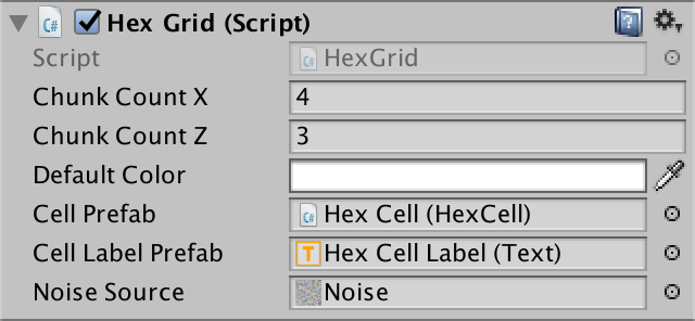
Specify the size in fragments.
Let's change
Awakeso that if necessary from the number of fragments the number of cells was calculated. Select the creation of cells in a separate method, so as not to litter Awake.voidAwake () {
HexMetrics.noiseSource = noiseSource;
gridCanvas = GetComponentInChildren<Canvas>();
hexMesh = GetComponentInChildren<HexMesh>();
cellCountX = chunkCountX * HexMetrics.chunkSizeX;
cellCountZ = chunkCountZ * HexMetrics.chunkSizeZ;
CreateCells();
}
voidCreateCells () {
cells = new HexCell[cellCountZ * cellCountX];
for (int z = 0, i = 0; z < cellCountZ; z++) {
for (int x = 0; x < cellCountX; x++) {
CreateCell(x, z, i++);
}
}
}Fragment prefab
To describe the mesh fragments, we need a new type of components.
using UnityEngine;
using UnityEngine.UI;
publicclassHexGridChunk : MonoBehaviour {
}
Next we will create a prefab fragment. We do this by duplicating a Hex Grid object and renaming it to Hex Grid Chunk . Remove its component
HexGridand add a component instead HexGridChunk. Then turn it into a prefab and remove the object from the scene.

Prefab fragment with its own canvas and mesh.
Since the copies of these fragments will be created
HexGrid, we will give him a link to the fragment prefab.public HexGridChunk chunkPrefab;
Now with the fragments.
Creating instances of fragments is a lot like creating instances of cells. We will track them using an array, and to fill it we will use a double loop.
	HexGridChunk[] chunks;
	voidAwake () {
		…
		CreateChunks();
		CreateCells();
	}
	voidCreateChunks () {
		chunks = new HexGridChunk[chunkCountX * chunkCountZ];
		for (int z = 0, i = 0; z < chunkCountZ; z++) {
			for (int x = 0; x < chunkCountX; x++) {
				HexGridChunk chunk = chunks[i++] = Instantiate(chunkPrefab);
				chunk.transform.SetParent(transform);
			}
		}
	}
The initialization of the fragment is similar to how we initialized the grid of hexagons. It sets everything in
Awakeand performs triangulation in Start. It requires a reference to its canvas and mesh, as well as an array for the cells. However, the fragment will not create these cells. This will still be done by the grid.publicclassHexGridChunk : MonoBehaviour {
HexCell[] cells;
HexMesh hexMesh;
Canvas gridCanvas;
voidAwake () {
gridCanvas = GetComponentInChildren<Canvas>();
hexMesh = GetComponentInChildren<HexMesh>();
cells = new HexCell[HexMetrics.chunkSizeX * HexMetrics.chunkSizeZ];
}
voidStart () {
hexMesh.Triangulate(cells);
}
}Assigning cells to fragments
HexGridstill creates all the cells. This is normal, but now we need to add each cell to the appropriate fragment, and not specify them using our own mesh and canvas.voidCreateCell (int x, int z, int i) {
…
HexCell cell = cells[i] = Instantiate<HexCell>(cellPrefab);
// cell.transform.SetParent(transform, false);
cell.transform.localPosition = position;
cell.coordinates = HexCoordinates.FromOffsetCoordinates(x, z);
cell.color = defaultColor;
…
Text label = Instantiate<Text>(cellLabelPrefab);
// label.rectTransform.SetParent(gridCanvas.transform, false);
label.rectTransform.anchoredPosition =
new Vector2(position.x, position.z);
label.text = cell.coordinates.ToStringOnSeparateLines();
cell.uiRect = label.rectTransform;
cell.Elevation = 0;
AddCellToChunk(x, z, cell);
}
voidAddCellToChunk (int x, int z, HexCell cell) {
}We can find the correct fragment using integer division
xand zthe size of the fragment.voidAddCellToChunk (int x, int z, HexCell cell) {
int chunkX = x / HexMetrics.chunkSizeX;
int chunkZ = z / HexMetrics.chunkSizeZ;
HexGridChunk chunk = chunks[chunkX + chunkZ * chunkCountX];
}Using intermediate results, we can also determine the local cell index in this fragment. After that you can add a cell to the fragment.
voidAddCellToChunk (int x, int z, HexCell cell) {
		int chunkX = x / HexMetrics.chunkSizeX;
		int chunkZ = z / HexMetrics.chunkSizeZ;
		HexGridChunk chunk = chunks[chunkX + chunkZ * chunkCountX];
		int localX = x - chunkX * HexMetrics.chunkSizeX;
		int localZ = z - chunkZ * HexMetrics.chunkSizeZ;
		chunk.AddCell(localX + localZ * HexMetrics.chunkSizeX, cell);
	}
Then it
HexGridChunk.AddCellputs the cell in its own array, and then it sets the parent elements for the cell and its UI.publicvoidAddCell (int index, HexCell cell) {
cells[index] = cell;
cell.transform.SetParent(transform, false);
cell.uiRect.SetParent(gridCanvas.transform, false);
}Cleaning up
At this stage, it
HexGridcan get rid of its child elements of the canvas and the mesh of hexagons, as well as code.// Canvas gridCanvas;// HexMesh hexMesh;voidAwake () {
HexMetrics.noiseSource = noiseSource;
// gridCanvas = GetComponentInChildren<Canvas>();// hexMesh = GetComponentInChildren<HexMesh>();
…
}
// void Start () {// hexMesh.Triangulate(cells);// }// public void Refresh () {// hexMesh.Triangulate(cells);// }Since we got rid of
Refresh, then should HexMapEditorno longer use it.voidEditCell (HexCell cell) {
cell.color = activeColor;
cell.Elevation = activeElevation;
// hexGrid.Refresh();
}
Cleared hexagon grid.
After starting the Play mode, the map still looks the same. But the hierarchy of objects will be different. Hex Grid now creates child objects of fragments that contain cells, as well as their mesh and canvas.

Child fragments in Play mode.
Perhaps we have some problems with the labels of the cells. Initially, we set the width of the label 5. This was enough to display two characters, which we had enough on a small map. But now we can have coordinates such as −10, in which there are three characters. They will not fit and will be trimmed. To fix this, increase the width of the cell label to 10, or even more.


Extended Cell Labels.
Now we can create much larger cards! Since we generate the entire grid at launch, it may take a long time to create large maps. But after completion we will have a huge space for experiments.
Correct cell editing
At the current stage, editing does not seem to work, because we are no longer updating the grid. We need to update individual fragments, so we add a method
Refreshto HexGridChunk.publicvoidRefresh () {
hexMesh.Triangulate(cells);
}When do we call this method? We updated the whole mesh every time, because we only had one mesh. But now we have a lot of fragments. Instead of updating all of them every time, it will be much more efficient to update the changed fragments. Otherwise, changing large cards will become a very brake operation.
But how do you know which fragment we update? The easiest way is to make each cell know which fragment it belongs to. Then the cell will be able to update its fragment when this cell changes. So let's give a
HexCelllink to its fragment.public HexGridChunk chunk;HexGridChunk may, when added, assign itself to the cell.publicvoidAddCell (int index, HexCell cell) {
cells[index] = cell;
cell.chunk = this;
cell.transform.SetParent(transform, false);
cell.uiRect.SetParent(gridCanvas.transform, false);
}Combining them, we add to the
HexCellmethod Refresh. Each time a cell is updated, it will simply update its fragment.voidRefresh () {
chunk.Refresh();
}We don’t have to be
HexCell.Refreshshared, because the cell itself knows better when it was changed. For example, after its height has been changed.publicint Elevation {
get {
return elevation;
}
set {
…
Refresh();
}
}In fact, we need to update it only when its height has changed to another value. She doesn't even need to re-calculate anything if we assign her the same height as before. Therefore, we can get out of the beginning of the setter.
publicint Elevation {
		get {
			return elevation;
		}
		set {
			if (elevation == value) {
				return;
			}
			…
		}
	}
However, we will also skip the calculations for the first time when the height is set to 0, because this is the default value of the grid height. To avoid this, let us make sure that the initial value is such that we never use.
int elevation = int.MinValue;What is int.MinValue?
Это наименьшее значение, которое может иметь integer. Так как в C# integer —
это 32-битное число, то существует 232 возможных integer, разделённых на положительные значения, отрицательные значения и ноль. Для обозначения отрицательности числа используется один бит.
Минимум — это −231 = −2 147 483 648. Мы никогда не будем использовать такой уровень высоты!
Максимум равен 231 − 1 = 2 147 483 647. Это на единицу меньше 231 из-за нуля.
To recognize the color change of a cell, we also need to turn it into a property. Rename it
Colorwith a capital letter, and then turn it into a property with a private variable color. The default color value is transparent black, which suits us.public Color Color {
get {
return color;
}
set {
if (color == value) {
return;
}
color = value;
Refresh();
}
}
Color color;Now when we start Play mode, we get null-reference exceptions. This is because we assigned default values to color and height before assigning the cell to its fragment. It is normal that at this stage we do not update the fragments, because we triangulate them after the completion of the entire initialization. In other words, we update the fragment only if it is assigned.
voidRefresh () {
		if (chunk) {
			chunk.Refresh();
		}
	}
We can finally change the cells again! However, a problem arises. When drawing along the edges of the fragments appear seams.

Errors on the boundaries of the fragments.
This is logical, because when a single cell changes, all connections with its neighbors also change. And these neighbors may be in other fragments. The simplest solution is to update all neighboring cells, if they are different.
voidRefresh () {
		if (chunk) {
			chunk.Refresh();
			for (int i = 0; i < neighbors.Length; i++) {
				HexCell neighbor = neighbors[i];
				if (neighbor != null && neighbor.chunk != chunk) {
					neighbor.chunk.Refresh();
				}
			}
		}
	}
Although this works, it may turn out that we update one fragment several times. And when we start painting a few cells at a time, everything will get worse.
But we are not obliged to immediately triangulate after updating the fragment. Instead, we simply write down what needs to be updated, and triangulate after the change is complete.
Since
HexGridChunknothing else does, we can use its enabled state to signal the need for an update. When updating it, we enable the component. Turning it on several times will not change anything. Later, the component is updated. We will perform triangulation at this stage and disable the component again. We use
LateUpdateinsteadUpdateto ensure that triangulation occurs after the completion of a change for the current frame.publicvoidRefresh () {
// hexMesh.Triangulate(cells);
enabled = true;
}
voidLateUpdate () {
hexMesh.Triangulate(cells);
enabled = false;
}What is the difference between Update and LateUpdate?
В каждом кадре методы
Update включённых компонентов на каком-то этапе вызываются в произвольном порядке. После их завершения то же самое происходит с методами LateUpdate. То есть существует два этапа обновления, ранний и поздний.Since our component is enabled by default by default, we no longer need to explicitly triangulate to
Start. Therefore, this method can be removed.// void Start () {// hexMesh.Triangulate(cells);// }
Fragments 20 by 20 containing 10,000 cells.
Generalized lists
Although we have significantly changed the way the grid is triangulated, it
HexMeshstill remains the same. All he needs to work is an array of cells. He does not care whether one mesh of hexagons, or several. But we have not yet considered the use of several meshes. Perhaps something can be improved here? Used
HexMeshlists are essentially temporary buffers. They are used only with triangulation. And the fragments are triangulated one at a time. Therefore, in reality, we need only one set of lists, and not one set for each object of the mesh of hexagons. This can be achieved by making the lists static.static List<Vector3> vertices = new List<Vector3>();
static List<Color> colors = new List<Color>();
static List<int> triangles = new List<int>();
voidAwake () {
GetComponent<MeshFilter>().mesh = hexMesh = new Mesh();
meshCollider = gameObject.AddComponent<MeshCollider>();
hexMesh.name = "Hex Mesh";
// vertices = new List<Vector3>();// colors = new List<Color>();// triangles = new List<int>();
}Are static lists really that important?
Это изменение внести очень просто и оно отражает способ использования списков. Поэтому стоит это сделать, несмотря на то, что пока нас не очень беспокоит производительность.
Это немного увеличивает эффективность кода, потому что при использовании обобщённых списков необходимо намного меньше выделяемой памяти. В случае карты 20 на 20 фрагментов это экономит больше 100МБ.
Это немного увеличивает эффективность кода, потому что при использовании обобщённых списков необходимо намного меньше выделяемой памяти. В случае карты 20 на 20 фрагментов это экономит больше 100МБ.
unitypackage
Camera control
A big camera is great, but it is useless if we cannot see it. To view the entire map, we need to move the camera. Also useful zoom. So let's create a camera that allows you to perform these actions.
Create a dummy object and name it Hex Map Camera . Drop its transform component so that it moves to the origin without changing its rotation and scale. Add a child object called Swivel to it , and add a child Stick object to it . Let's make the main camera a child element of the Stick, and reset its transform component.

The hierarchy of the camera.
The task of the camera hinge (Swivel) is to control the angle at which the camera looks at the map. Let him turn (45, 0, 0). The stick controls the distance at which the cameras are located. We assign it a position (0, 0, -45).
Now we need a component to manage this system. Assign this component to the root of the camera hierarchy. Give him a link to the hinge and handle, getting them in
Awake.using UnityEngine;
publicclassHexMapCamera : MonoBehaviour {
Transform swivel, stick;
voidAwake () {
swivel = transform.GetChild(0);
stick = swivel.GetChild(0);
}
}
Camera cards of hexagons.
Zoom
The first function we create is zooming (zoom). We can control the current zoom level with the variable float. A value of 0 means that we are completely distant, and a value of 1 means that we are completely close. Let's start with the maximum zoom.
float zoom = 1f;Zoom will usually be performed by mouse wheel or analog control. We can implement it using the default Mouse ScrollWheel input axis . Add a method
Updatethat checks for the presence of an input delta, and if there is one, it calls the method for changing the zoom.voidUpdate () {
float zoomDelta = Input.GetAxis("Mouse ScrollWheel");
if (zoomDelta != 0f) {
AdjustZoom(zoomDelta);
}
}
voidAdjustZoom (float delta) {
}To change the zoom level, we will simply add a delta to it, and then limit the value (clamp) to remain in the range of 0–1.
voidAdjustZoom (float delta) {
		zoom = Mathf.Clamp01(zoom + delta);
	}
When you zoom in and zoom out, the distance to the camera should change accordingly. This can be done by changing the position of the knob in Z. We add two common float variables to adjust the position of the knob with the minimum and maximum zoom. Since we are developing a relatively small map, let's set the values to -250 and -45.
publicfloat stickMinZoom, stickMaxZoom;After changing the zoom, we perform linear interpolation between these two values based on the new zoom value. Then update the pen position.
voidAdjustZoom (float delta) {
		zoom = Mathf.Clamp01(zoom + delta);
		float distance = Mathf.Lerp(stickMinZoom, stickMaxZoom, zoom);
		stick.localPosition = new Vector3(0f, 0f, distance);
	}
The minimum and maximum value of the stick.
Now the zoom works, but so far it is not very useful. Usually at a distance of the zoom, the camera turns into a top view. We can do this by turning the hinge. Therefore, we add the variables min and max for the hinge. Give them the values of 90 and 45.
publicfloat swivelMinZoom, swivelMaxZoom;As in the case with the handle position, we interpolate to find a suitable zoom angle. Then we set the rotation of the hinge.
voidAdjustZoom (float delta) {
		zoom = Mathf.Clamp01(zoom + delta);
		float distance = Mathf.Lerp(stickMinZoom, stickMaxZoom, zoom);
		stick.localPosition = new Vector3(0f, 0f, distance);
		float angle = Mathf.Lerp(swivelMinZoom, swivelMaxZoom, zoom);
		swivel.localRotation = Quaternion.Euler(angle, 0f, 0f);
	}
The minimum and maximum Swivel values.
The rate of change of the zoom can be adjusted by changing the sensitivity of the input parameters of the mouse wheel. They can be found in Edit / Project Settings / Input . For example, changing them from 0.1 to 0.025, we get a slower and smoother zoom.

Mouse wheel input options.
Move
Now let's move on to moving the camera. The movement in the direction of X and Z we must implement in
Update, as is the case with the zoom. We can use for this input axis Horizontal and Vertical . This will allow us to move the camera with the arrows and WASD keys.voidUpdate () {
float zoomDelta = Input.GetAxis("Mouse ScrollWheel");
if (zoomDelta != 0f) {
AdjustZoom(zoomDelta);
}
float xDelta = Input.GetAxis("Horizontal");
float zDelta = Input.GetAxis("Vertical");
if (xDelta != 0f || zDelta != 0f) {
AdjustPosition(xDelta, zDelta);
}
}
voidAdjustPosition (float xDelta, float zDelta) {
}The simplest approach is to get the current position of the camera system, add the deltas X and Z to it, and assign the result to the system position.
voidAdjustPosition (float xDelta, float zDelta) {
		Vector3 position = transform.localPosition;
		position += new Vector3(xDelta, 0f, zDelta);
		transform.localPosition = position;
	}
Due to this, the camera will move while holding the arrows or WASD, but not at a constant speed. It will depend on the frame rate. To determine the distance to move, we use the time delta, as well as the desired speed of movement. Therefore, we add a common variable
moveSpeedand set it to 100, and then multiply it by the time delta to get the delta position.publicfloat moveSpeed;
voidAdjustPosition (float xDelta, float zDelta) {
float distance = moveSpeed * Time.deltaTime;
Vector3 position = transform.localPosition;
position += new Vector3(xDelta, 0f, zDelta) * distance;
transform.localPosition = position;
}
Moving speed
Now we can move at a constant speed along the X or Z axes. But when moving along both axes at the same time (diagonally), the movement will be faster. To fix this, we need to normalize the delta vector. This will use it as a referral.
voidAdjustPosition (float xDelta, float zDelta) {
		Vector3 direction = new Vector3(xDelta, 0f, zDelta).normalized;
		float distance = moveSpeed * Time.deltaTime;
		Vector3 position = transform.localPosition;
		position += direction * distance;
		transform.localPosition = position;
	}
The diagonal movement is now implemented correctly, but suddenly it turns out that the camera continues to move for quite a long time even after all the keys are released. This happens because the input axes do not instantly jump to the limit values immediately after pressing the keys. They need some time for this. The same is true for releasing keys. It takes time to return to zero axis values. However, since we normalized the input values, the maximum speed is kept constant.
We can adjust the input parameters to get rid of delays, but they give a feeling of smoothness that is worth saving. We can apply the most extreme value of the axes as the attenuation coefficient of the motion.
		Vector3 direction = new Vector3(xDelta, 0f, zDelta).normalized;
		float damping = Mathf.Max(Mathf.Abs(xDelta), Mathf.Abs(zDelta));
		float distance = moveSpeed * damping * Time.deltaTime;
Motion with damping.
Now the movement works well, at least with the zoom. But at a distance it turns out to be too slow. With a reduced zoom, we need to speed up. This can be done by replacing one variable
moveSpeedwith two for the minimum and maximum zoom, and then performing the interpolation. Assign them the values 400 and 100.// public float moveSpeed;publicfloat moveSpeedMinZoom, moveSpeedMaxZoom;
voidAdjustPosition (float xDelta, float zDelta) {
Vector3 direction = new Vector3(xDelta, 0f, zDelta).normalized;
float damping = Mathf.Max(Mathf.Abs(xDelta), Mathf.Abs(zDelta));
float distance =
Mathf.Lerp(moveSpeedMinZoom, moveSpeedMaxZoom, zoom) *
damping * Time.deltaTime;
Vector3 position = transform.localPosition;
position += direction * distance;
transform.localPosition = position;
}
Movement speed varies with zoom level.
Now we can quickly navigate the map! In fact, we can move far beyond the map, but this is undesirable. The camera must remain inside the card. To ensure this, we need to know the boundaries of the map, so we need a reference to the grid. Add and connect it.
public HexGrid grid;
You need to request the size of the grid.
After moving to a new position, we will limit it with the help of a new method.
voidAdjustPosition (float xDelta, float zDelta) {
		…
		transform.localPosition = ClampPosition(position);
	}
	Vector3 ClampPosition (Vector3 position) {
		return position;
	}
Position X has a minimum value of 0, and the maximum is determined by the size of the map.
Vector3 ClampPosition (Vector3 position) {
		float xMax =
			grid.chunkCountX * HexMetrics.chunkSizeX *
			(2f * HexMetrics.innerRadius);
		position.x = Mathf.Clamp(position.x, 0f, xMax);
		return position;
	}
The same applies to position Z.
Vector3 ClampPosition (Vector3 position) {
		float xMax =
			grid.chunkCountX * HexMetrics.chunkSizeX *
			(2f * HexMetrics.innerRadius);
		position.x = Mathf.Clamp(position.x, 0f, xMax);
		float zMax =
			grid.chunkCountZ * HexMetrics.chunkSizeZ *
			(1.5f * HexMetrics.outerRadius);
		position.z = Mathf.Clamp(position.z, 0f, zMax);
		return position;
	}
In fact, this is a bit inaccurate. The origin is in the center of the cell, not on the left. Therefore, we want the camera to stop at the center of the rightmost cells. To do this, subtract half the cell from the maximum X.
float xMax =
			(grid.chunkCountX * HexMetrics.chunkSizeX - 0.5f) *
			(2f * HexMetrics.innerRadius);
		position.x = Mathf.Clamp(position.x, 0f, xMax);
For the same reason, you need to reduce the maximum of Z. Since the metrics are slightly different, we need to subtract the full cell.
float zMax =
			(grid.chunkCountZ * HexMetrics.chunkSizeZ - 1) *
			(1.5f * HexMetrics.outerRadius);
		position.z = Mathf.Clamp(position.z, 0f, zMax);
With the movement we finished, only a small detail remained. Sometimes the UI responds to the arrow keys, and this causes the slider to move as the camera moves. This happens when the UI considers itself active after you have pressed it and the cursor continues to be above it.
You can disable UI from listening to keyboard input. This can be done by ordering the EventSystem object not to execute Send Navigation Events .

No more navigation events.
Turn
Want to see what is behind the cliff? It would be convenient to be able to rotate the camera! Let's add this feature.
The zoom level is not important for rotation, only speed is enough. Add a common variable
rotationSpeedand set it to a value of 180 degrees. Check the turn delta in Update, sampling the Rotation axis and changing the turn if necessary.publicfloat rotationSpeed;
voidUpdate () {
float zoomDelta = Input.GetAxis("Mouse ScrollWheel");
if (zoomDelta != 0f) {
AdjustZoom(zoomDelta);
}
float rotationDelta = Input.GetAxis("Rotation");
if (rotationDelta != 0f) {
AdjustRotation(rotationDelta);
}
float xDelta = Input.GetAxis("Horizontal");
float zDelta = Input.GetAxis("Vertical");
if (xDelta != 0f || zDelta != 0f) {
AdjustPosition(xDelta, zDelta);
}
}
voidAdjustRotation (float delta) {
}
Turning speed.
In fact, there is no default Rotation axis . We have to create it ourselves. Let's go over the input parameters and duplicate the topmost Vertical entry . Change the duplicate name to Rotation and change the keys to QE and a comma (,) with a period (.).

The axis of the input rotation.
I downloaded unitypackage, why do I not have this input?
Параметры ввода распространяются на проект. Поэтому они не включаются в пакеты Unity. К счастью, их легко можно добавить самостоятельно. Если этого не сделать, то вы получите исключение, сообщающее об отсутствующей оси ввода.
Angle of rotation we will track and change c
AdjustRotation. After which we will rotate the entire camera system.float rotationAngle;
voidAdjustRotation (float delta) {
rotationAngle += delta * rotationSpeed * Time.deltaTime;
transform.localRotation = Quaternion.Euler(0f, rotationAngle, 0f);
}Since the full circle is equal to 360 degrees, we turn the rotation angle so that it is in the range from 0 to 360.
voidAdjustRotation (float delta) {
		rotationAngle += delta * rotationSpeed * Time.deltaTime;
		if (rotationAngle < 0f) {
			rotationAngle += 360f;
		}
		elseif (rotationAngle >= 360f) {
			rotationAngle -= 360f;
		}
		transform.localRotation = Quaternion.Euler(0f, rotationAngle, 0f);
	}
Turn in action.
Now the turn is working. If you check it, you can see that the movement is absolutely. Therefore, after turning 180 degrees, the movement will be opposite to what was expected. For the user, it would be much more convenient for the movement to be performed relative to the camera angle of view. We can do this by multiplying the current turn by the direction of travel.
voidAdjustPosition (float xDelta, float zDelta) {
		Vector3 direction =
			transform.localRotation *
			new Vector3(xDelta, 0f, zDelta).normalized;
		…
	}
Relative movement
unitypackage
Advanced Editing
Now that we have a larger map, we can improve the map editing tools. Changing one cell at a time is too long, so it would be nice to create a larger brush. It will also be convenient if you could choose to draw a color or change the height, leaving everything else the same.
Optional color and height
We can make colors optional by adding an empty selection to the toggle group. Duplicate one of the color switches and replace its label with --- or something like that to indicate that it is not a color. Then we change the argument of its event On Value Changed to −1.

Invalid color index.
Of course, this index is invalid for an array of colors. We can use it to determine whether color should be applied to cells.
bool applyColor;
	publicvoidSelectColor (int index) {
		applyColor = index >= 0;
		if (applyColor) {
			activeColor = colors[index];
		}
	}
	voidEditCell (HexCell cell) {
		if (applyColor) {
			cell.Color = activeColor;
		}
		cell.Elevation = activeElevation;
	}
The height is controlled by a slider, so we cannot add a switch to it. Instead, we can use a separate switch to enable and disable height editing. By default, it will be enabled.
bool applyElevation = true;
	voidEditCell (HexCell cell) {
		if (applyColor) {
			cell.Color = activeColor;
		}
		if (applyElevation) {
			cell.Elevation = activeElevation;
		}
	}
Add a new height switch to the UI. I will also put everything on a new panel, and make the height slider horizontal so that the UI is more beautiful.

Optional color and height.
To enable height, we need a new method that we connect to the UI.
publicvoidSetApplyElevation (bool toggle) {
		applyElevation = toggle;
	}
By connecting it to the height switch, make sure that the bool dynamic method is used at the top of the list of methods. Correct versions do not display a check box in the inspector.

Pass the state of the altitude switch.
Now we can choose only coloring with flowers or only height. Or both, as usual. We can even choose not to change one or the other, but for now this is not particularly useful for us.
Switch between color and height.
Why is the height off when choosing a color?
Такое бывает, когда все переключатели принадлежат к одной toggle group. Вероятно, вы дублировали один из переключателей выбора цвета и изменяете его, но не убрали его toggle group.
Brush size
To support the resizable brush, we add an integer variable
brushSizeand a method for setting it via UI. We will use the slider, so again we will have to convert the value from float to int.int brushSize;
publicvoidSetBrushSize (float size) {
brushSize = (int)size;
}
Brush size slider.
You can create a new slider by duplicating the height slider. Change its maximum value to 4 and attach it to the appropriate method. I also added a tag to him.

Brush size slider settings.
Now that we can edit several cells at the same time, we need to use the method
EditCells. This method will call EditCellfor all cells involved. Initially the selected cell will be considered the center of the brush.voidHandleInput () {
Ray inputRay = Camera.main.ScreenPointToRay(Input.mousePosition);
RaycastHit hit;
if (Physics.Raycast(inputRay, out hit)) {
EditCells(hexGrid.GetCell(hit.point));
}
}
voidEditCells (HexCell center) {
}
voidEditCell (HexCell cell) {
…
}The size of the brush determines the radius of the edit. With a radius of 0, this will be only one central cell. With a radius of 1, this will be the center and its neighbors. With a radius of 2, center neighbors and their immediate neighbors are included. And so on.

Up to a radius of 3.
To edit cells, you need to go around them in a loop. First we need the X and Z coordinates of the center.
voidEditCells (HexCell center) {
		int centerX = center.coordinates.X;
		int centerZ = center.coordinates.Z;
	}
We find the minimum Z coordinate by subtracting the radius. So we define the zero string. Starting from this line, we perform a loop until we cover the line in the center.
voidEditCells (HexCell center) {
		int centerX = center.coordinates.X;
		int centerZ = center.coordinates.Z;
		for (int r = 0, z = centerZ - brushSize; z <= centerZ; z++, r++) {
		}
	}
The first cell in the bottom row has the same X coordinate as the center cell. This coordinate decreases as the line number increases.
The last cell always has an X coordinate equal to the center coordinate plus radius.
Now we can loop around each row and get the cells by their coordinates.
for (int r = 0, z = centerZ - brushSize; z <= centerZ; z++, r++) {
			for (int x = centerX - r; x <= centerX + brushSize; x++) {
				EditCell(hexGrid.GetCell(new HexCoordinates(x, z)));
			}
		}
We do not yet have a method
HexGrid.GetCellwith a coordinate parameter, so we will create it. Convert to offset coordinates and get a cell.public HexCell GetCell (HexCoordinates coordinates) {
int z = coordinates.Z;
int x = coordinates.X + z / 2;
return cells[x + z * cellCountX];
}
The bottom of the brush, size 2.
The rest of the brush we cover, performing a cycle from top to bottom to the center. In this case, the logic is mirrored and the central line must be deleted.
voidEditCells (HexCell center) {
		int centerX = center.coordinates.X;
		int centerZ = center.coordinates.Z;
		for (int r = 0, z = centerZ - brushSize; z <= centerZ; z++, r++) {
			for (int x = centerX - r; x <= centerX + brushSize; x++) {
				EditCell(hexGrid.GetCell(new HexCoordinates(x, z)));
			}
		}
		for (int r = 0, z = centerZ + brushSize; z > centerZ; z--, r++) {
			for (int x = centerX - brushSize; x <= centerX + r; x++) {
				EditCell(hexGrid.GetCell(new HexCoordinates(x, z)));
			}
		}
	}
The whole brush is size 2.
It works, unless our brush goes beyond the grid. When this happens, we get the index-out-of-range exception. To avoid this, check the boundaries in
HexGrid.GetCelland return nullwhen a non-existing cell is requested.public HexCell GetCell (HexCoordinates coordinates) {
int z = coordinates.Z;
if (z < 0 || z >= cellCountZ) {
returnnull;
}
int x = coordinates.X + z / 2;
if (x < 0 || x >= cellCountX) {
returnnull;
}
return cells[x + z * cellCountX];
}To avoid null-reference-exception, you
HexMapEditormust check before editing whether a cell really exists.voidEditCell (HexCell cell) {
if (cell) {
if (applyColor) {
cell.Color = activeColor;
}
if (applyElevation) {
cell.Elevation = activeElevation;
}
}
}Use multiple brush sizes.
Toggle visibility of cell labels
Most often, we don’t need to see the labels of the cells. So let's make them optional. Since each fragment controls its own canvas, let's add a method
ShowUIto HexGridChunk. When the UI needs to be visible, we activate canvas. Otherwise, deactivate it.publicvoidShowUI (bool visible) {
gridCanvas.gameObject.SetActive(visible);
}Let's hide the UI by default.
voidAwake () {
		gridCanvas = GetComponentInChildren<Canvas>();
		hexMesh = GetComponentInChildren<HexMesh>();
		cells = new HexCell[HexMetrics.chunkSizeX * HexMetrics.chunkSizeZ];
		ShowUI(false);
	}
Since the visibility of the UI switches for the whole map, we will add a method
ShowUIto the HexGrid. He simply sends the request to his fragments.publicvoidShowUI (bool visible) {
for (int i = 0; i < chunks.Length; i++) {
chunks[i].ShowUI(visible);
}
}HexMapEditor gets the same method by passing the request to the grid.publicvoidShowUI (bool visible) {
hexGrid.ShowUI(visible);
}Finally, we can add a switch to the UI and connect it.

Switch visibility tags.
unitypackage
Part 6: Rivers
- Adding to the cells of these rivers.
- Drag and drop support for drawing rivers.
- Creation of river channels.
- Use several meshes per fragment.
- Creating a common pool of lists.
- Triangulation and animation of flowing water.
In the previous part, we talked about supporting large cards. Now we can move on to larger scale relief elements. This time we will talk about the rivers.

Rivers flow from the mountains.
Cells with rivers
There are three ways to add rivers to a grid of hexagons. The first way is to allow them to flow from cell to cell. This is how it is implemented in Endless Legend. The second way is to allow them to flow between the cells, from the edge to the edge. This is how it is implemented in Civilization 5. The third way is not to create special river structures at all, but to use water cells to envision them. So the rivers are realized in Age of Wonders 3.
In our case, the edges of the cells are already occupied by slopes and cliffs. This leaves little room for rivers. Therefore, we will make them flow from cell to cell. This means that in each cell either there will be no river, or a river will flow through it, or there will be a beginning or end of a river in it. In those cells through which the river flows, it can flow straight, make a turn one step or two steps.

Five possible configurations of the rivers.
We will not support branching or merging rivers. This will complicate things even more, especially the flow of water. Also, we will not be puzzled by large volumes of water. We will look at them in another tutorial.
River tracking
A cell through which a river flows can be considered at the same time as having an incoming and outgoing river. If it contains the beginning of a river, then it has only the outgoing river. And if it contains the end of a river, then it only has an incoming river. We can store this information in
HexCellusing two boolean values.bool hasIncomingRiver, hasOutgoingRiver;But this is not enough. We also need to know the direction of these rivers. In the case of an outgoing river, it indicates where it is going. In the case of an incoming river, it indicates where it came from.
bool hasIncomingRiver, hasOutgoingRiver;
	HexDirection incomingRiver, outgoingRiver;
We will need this information when triangulating cells, so we’ll add properties to have access to it. We will not support assigning them directly. To do this, we will further add a separate method.
publicbool HasIncomingRiver {
		get {
			return hasIncomingRiver;
		}
	}
	publicbool HasOutgoingRiver {
		get {
			return hasOutgoingRiver;
		}
	}
	public HexDirection IncomingRiver {
		get {
			return incomingRiver;
		}
	}
	public HexDirection OutgoingRiver {
		get {
			return outgoingRiver;
		}
	}
The important question is whether there is a river in the cell, regardless of the details. So let's add a property for this too.
publicbool HasRiver {
		get {
			return hasIncomingRiver || hasOutgoingRiver;
		}
	}
Another logical question is whether the beginning or end of the river is in the cell. If the state of the incoming and outgoing river is different, then this is exactly the case. Therefore, we make this one more property.
publicbool HasRiverBeginOrEnd {
		get {
			return hasIncomingRiver != hasOutgoingRiver;
		}
	}
Finally, it will be helpful to know whether a river flows through a certain edge, be it incoming or outgoing.
publicboolHasRiverThroughEdge (HexDirection direction) {
		return
			hasIncomingRiver && incomingRiver == direction ||
			hasOutgoingRiver && outgoingRiver == direction;
	}
River removal
Before we start adding a river to a cell, let's first implement support for deleting rivers. To begin with, we will write a method for removing only the outgoing part of the river.
If there is no outgoing river in the cell, then nothing needs to be done. Otherwise, disable it and perform the update.
publicvoidRemoveOutgoingRiver () {
		if (!hasOutgoingRiver) {
			return;
		}
		hasOutgoingRiver = false;
		Refresh();
	}
But that is not all. The outgoing river must move somewhere further. Therefore, there must be a neighbor with the incoming river. We need to get rid of her too.
publicvoidRemoveOutgoingRiver () {
		if (!hasOutgoingRiver) {
			return;
		}
		hasOutgoingRiver = false;
		Refresh();
		HexCell neighbor = GetNeighbor(outgoingRiver);
		neighbor.hasIncomingRiver = false;
		neighbor.Refresh();
	}
Can't a river flow out of a map?
Хотя можно реализовать поддержку таких рек, мы этого делать не будем. Поэтому нам не нужно проверять, существует ли сосед.
Removing a river from a cell changes only the appearance of this cell. Unlike editing height or color, it does not affect neighbors. Therefore, we need to update only the cell itself, but not its neighbors.
publicvoidRemoveOutgoingRiver () {
		if (!hasOutgoingRiver) {
			return;
		}
		hasOutgoingRiver = false;
		RefreshSelfOnly();
		HexCell neighbor = GetNeighbor(outgoingRiver);
		neighbor.hasIncomingRiver = false;
		neighbor.RefreshSelfOnly();
	}
This method
RefreshSelfOnlysimply updates the fragment to which the cell belongs. Since we do not change the river during grid initialization, we don’t need to worry about whether a fragment has already been assigned.voidRefreshSelfOnly () {
chunk.Refresh();
}Removing incoming rivers works the same way.
publicvoidRemoveIncomingRiver () {
		if (!hasIncomingRiver) {
			return;
		}
		hasIncomingRiver = false;
		RefreshSelfOnly();
		HexCell neighbor = GetNeighbor(incomingRiver);
		neighbor.hasOutgoingRiver = false;
		neighbor.RefreshSelfOnly();
	}
And the removal of the entire river simply means the removal of both the incoming and outgoing parts of the river.
publicvoidRemoveRiver () {
		RemoveOutgoingRiver();
		RemoveIncomingRiver();
	}
Adding rivers
To support the creation of rivers, we need a method for defining the outgoing river of a cell. It must redefine all previous outgoing rivers and set the appropriate incoming river.
For a start, we don’t need to do anything if the river already exists.
publicvoidSetOutgoingRiver (HexDirection direction) {
		if (hasOutgoingRiver && outgoingRiver == direction) {
			return;
		}
	}
Next, we need to make sure that there is a neighbor in the right direction. In addition, rivers can not flow upwards. Therefore, we must complete the operation if the neighbor is higher.
		HexCell neighbor = GetNeighbor(direction);
		if (!neighbor || elevation < neighbor.elevation) {
			return;
		}
Next we need to clear the previous outgoing river. And also we need to remove the incoming river if it overlaps a new outgoing river.
		RemoveOutgoingRiver();
		if (hasIncomingRiver && incomingRiver == direction) {
			RemoveIncomingRiver();
		}
Now we can proceed to setting up the outgoing river.
		hasOutgoingRiver = true;
		outgoingRiver = direction;
		RefreshSelfOnly();
And do not forget to set the incoming river for another cell after deleting its current incoming river, if it exists.
		neighbor.RemoveIncomingRiver();
		neighbor.hasIncomingRiver = true;
		neighbor.incomingRiver = direction.Opposite();
		neighbor.RefreshSelfOnly();
Getting rid of the rivers flowing up
Now that we have made it so that only the right rivers can be added, other actions can still create the wrong ones. When we change the height of the cell, we must again forcefully make sure that the rivers can only flow down. All wrong rivers need to be removed.
publicint Elevation {
		get {
			return elevation;
		}
		set {
			…
			if (
				hasOutgoingRiver &&
				elevation < GetNeighbor(outgoingRiver).elevation
			) {
				RemoveOutgoingRiver();
			}
			if (
				hasIncomingRiver &&
				elevation > GetNeighbor(incomingRiver).elevation
			) {
				RemoveIncomingRiver();
			}
			Refresh();
		}
	}
unitypackage
River change
To support river editing, we need to add a river switch to the UI. In fact. we need support for three editing modes. We need to either ignore the rivers, or add them, or delete them. We can use a simple auxiliary listing of switches to track the status. Since we will only use it inside the editor, we can define it inside the class
HexMapEditor, along with the river mode field.enum OptionalToggle {
Ignore, Yes, No
}
OptionalToggle riverMode;And we will need a method to change the mode of the river through the UI.
publicvoidSetRiverMode (int mode) {
		riverMode = (OptionalToggle)mode;
	}
To control the river mode, add three switches to the UI and connect them to the new toggle group, as we did with the colors. I configured the switches so that their labels are under the flags. Because of this, they will remain thin enough to fit all three options in one line.

UI rec.
Why not use the drop-down list?
Если хотите, можете использовать раскрывающийся список. К сожалению dropdown list в Unity не может обрабатывать рекомпиляции и в режиме Play. Пункт списка будет утерян, поэтому после рекомпиляции он будет бесполезен.
Drag and Drop Recognition
To create a river, we need both a cell and a direction. At the moment
HexMapEditordoes not provide us with this information. Therefore, we need to add drag and drop support from one cell to another. We need to know if this drag will be correct and also determine its direction. And to recognize drag and drop, we need to remember the previous cell.
bool isDrag;
	HexDirection dragDirection;
	HexCell previousCell;
Initially, when dragging is not performed, there is no previous cell. That is, when there is no input or we do not interact with the map, you need to assign a value to it
null.voidUpdate () {
if (
Input.GetMouseButton(0) &&
!EventSystem.current.IsPointerOverGameObject()
) {
HandleInput();
}
else {
previousCell = null;
}
}
voidHandleInput () {
Ray inputRay = Camera.main.ScreenPointToRay(Input.mousePosition);
RaycastHit hit;
if (Physics.Raycast(inputRay, out hit)) {
EditCells(hexGrid.GetCell(hit.point));
}
else {
previousCell = null;
}
}The current cell is the one we found by intersecting the beam with the mesh. After the cell editing is completed, it is updated and becomes the previous cell for the new update.
voidHandleInput () {
		Ray inputRay = Camera.main.ScreenPointToRay(Input.mousePosition);
		RaycastHit hit;
		if (Physics.Raycast(inputRay, out hit)) {
			HexCell currentCell = hexGrid.GetCell(hit.point);
			EditCells(currentCell);
			previousCell = currentCell;
		}
		else {
			previousCell = null;
		}
	}
After determining the current cell, we can compare it with the previous cell, if it exists. If we get two different cells, then we may have the correct drag and we need to check this. Otherwise, it is not exactly dragging.
if (Physics.Raycast(inputRay, out hit)) {
			HexCell currentCell = hexGrid.GetCell(hit.point);
			if (previousCell && previousCell != currentCell) {
				ValidateDrag(currentCell);
			}
			else {
				isDrag = false;
			}
			EditCells(currentCell);
			previousCell = currentCell;
			isDrag = true;
		}
How do we check dragging? Checking whether the current cell is a neighbor of the previous one. We check this by circumventing its neighbors in a loop. If we find a match, we also immediately recognize the direction of drag and drop.
voidValidateDrag (HexCell currentCell) {
		for (
			dragDirection = HexDirection.NE;
			dragDirection <= HexDirection.NW;
			dragDirection++
		) {
			if (previousCell.GetNeighbor(dragDirection) == currentCell) {
				isDrag = true;
				return;
			}
		}
		isDrag = false;
	}
Do not we create with this dragging drag?
Когда мы перемещаем курсор вдоль рёбер ячейки, она в результате может быстро колебаться между двумя этими ячейками. Это и в самом деле может привести к «дрожащим» перетаскиваниям, но не всё так плохо.
Мы можем избежать этого, запоминая предыдущее перетаскивание. Благодаря этому следующее перетаскивание не будет сразу же идти в противоположном направлении.
Мы можем избежать этого, запоминая предыдущее перетаскивание. Благодаря этому следующее перетаскивание не будет сразу же идти в противоположном направлении.
Cell change
Now that we can recognize drag and drop, we can define outgoing rivers. We can also delete rivers, it does not require dragging support.
voidEditCell (HexCell cell) {
		if (cell) {
			if (applyColor) {
				cell.Color = activeColor;
			}
			if (applyElevation) {
				cell.Elevation = activeElevation;
			}
			if (riverMode == OptionalToggle.No) {
				cell.RemoveRiver();
			}
			elseif (isDrag && riverMode == OptionalToggle.Yes) {
				previousCell.SetOutgoingRiver(dragDirection);
			}
		}
	}
This code will draw the river from the previous cell to the current one. But he ignores the size of the brush. This is quite logical, but let's draw the rivers for all cells covered with a brush. This can be done by performing operations on the edited cell. In our case, we need to make sure that another cell really exists.
elseif (isDrag && riverMode == OptionalToggle.Yes) {
				HexCell otherCell = cell.GetNeighbor(dragDirection.Opposite());
				if (otherCell) {
					otherCell.SetOutgoingRiver(dragDirection);
				}
			}
Now we can edit the rivers, but we don’t see them yet. We can verify that this works by examining the altered cells in the debugger inspector.

Cell with river in the debug inspector.
What is a debug inspector?
Мы можем переключаться между обычным и отладочным режимами инспектора через его меню вкладки. Оно открывается значком в верхнем правом углу вкладки. Находясь в режиме отладки, инспектор отображает сырые данные объектов.
unitypackage
Riverbed between cells
During river triangulation, we need to take into account two parts: the location of the river bed and the water flowing through it. First, we will create a channel, and leave water for later.
The simplest part of the river is where it flows in the junctions between the cells. For the time being we triangulate this area with a strip of three quad. We can add to it the riverbed, lowering the middle quad and adding two walls of the channel.

Adding river to the rib strip.
For this, in the case of a river, two additional quad will be required and a channel with two vertical walls will be created. An alternative approach is to use four quad. Then we will lower the middle top to create a bed with sloping walls.

Always four quad.
Constant use of the same number of quadrilaterals is convenient, so let's choose this option.
Adding a vertex edge
The transition from three to four per edge requires the creation of an additional vertex of the edge. Rewrite
EdgeVertices, first rename v4to v5, and then rename v3to v4. Actions in this order ensure that all code will continue to refer to the correct vertices. Use the rename or refactor option of your editor to apply the changes everywhere. Otherwise, you will have to manually inspect the entire code and make changes.public Vector3 v1, v2, v4, v5;After renaming everything, add a new one
v3.public Vector3 v1, v2, v3, v4, v5;Add a new vertex to the constructor. It is located in the middle between the corner vertices. In addition, the other vertices should now be in ½ and ¾, and not in & frac13; and & frac23 ;.
publicEdgeVertices (Vector3 corner1, Vector3 corner2) {
		v1 = corner1;
		v2 = Vector3.Lerp(corner1, corner2, 0.25f);
		v3 = Vector3.Lerp(corner1, corner2, 0.5f);
		v4 = Vector3.Lerp(corner1, corner2, 0.75f);
		v5 = corner2;
	}
Add
v3and in TerraceLerp.publicstatic EdgeVertices TerraceLerp (
EdgeVertices a, EdgeVertices b, int step)
{
EdgeVertices result;
result.v1 = HexMetrics.TerraceLerp(a.v1, b.v1, step);
result.v2 = HexMetrics.TerraceLerp(a.v2, b.v2, step);
result.v3 = HexMetrics.TerraceLerp(a.v3, b.v3, step);
result.v4 = HexMetrics.TerraceLerp(a.v4, b.v4, step);
result.v5 = HexMetrics.TerraceLerp(a.v5, b.v5, step);
return result;
}Now I
HexMeshneed to include an additional vertex in the fans of the edge triangles.voidTriangulateEdgeFan (Vector3 center, EdgeVertices edge, Color color) {
AddTriangle(center, edge.v1, edge.v2);
AddTriangleColor(color);
AddTriangle(center, edge.v2, edge.v3);
AddTriangleColor(color);
AddTriangle(center, edge.v3, edge.v4);
AddTriangleColor(color);
AddTriangle(center, edge.v4, edge.v5);
AddTriangleColor(color);
}And also in his strip of quadrangles.
voidTriangulateEdgeStrip (
		EdgeVertices e1, Color c1,
		EdgeVertices e2, Color c2
	) {
		AddQuad(e1.v1, e1.v2, e2.v1, e2.v2);
		AddQuadColor(c1, c2);
		AddQuad(e1.v2, e1.v3, e2.v2, e2.v3);
		AddQuadColor(c1, c2);
		AddQuad(e1.v3, e1.v4, e2.v3, e2.v4);
		AddQuadColor(c1, c2);
		AddQuad(e1.v4, e1.v5, e2.v4, e2.v5);
		AddQuadColor(c1, c2);
	}

Comparison of four and five vertices per edge.
The height of the river bed
We created the channel by dropping the bottom edge of the edge. It determines the vertical position of the river bed. Although the exact vertical position of each cell is distorted, we must maintain the same height of the river bed in the cells with the same height. Thanks to this water will not have to flow upstream. In addition, the bed should be low enough to remain at the bottom, even in the case of the most vertical cells deviating at the same time, leaving enough space for water.
Let's set this offset in
HexMetricsand express it as height. Offsets one level will suffice.publicconstfloat streamBedElevationOffset = -1f;We can use this metric to add properties
HexCellto get the vertical position of the river bed of the cell.publicfloat StreamBedY {
get {
return
(elevation + HexMetrics.streamBedElevationOffset) *
HexMetrics.elevationStep;
}
}Creating a channel
When
HexMeshone of the six triangular parts of a cell triangulates, we can determine if a river flows along its edge. If so, then we can lower the middle edge of the rib to the height of the river bed.voidTriangulate (HexDirection direction, HexCell cell) {
Vector3 center = cell.Position;
EdgeVertices e = new EdgeVertices(
center + HexMetrics.GetFirstSolidCorner(direction),
center + HexMetrics.GetSecondSolidCorner(direction)
);
if (cell.HasRiverThroughEdge(direction)) {
e.v3.y = cell.StreamBedY;
}
TriangulateEdgeFan(center, e, cell.Color);
if (direction <= HexDirection.SE) {
TriangulateConnection(direction, cell, e);
}
}
Change the average vertex of the edge.
We can see the first signs of the river appear, but at the same time holes in the relief appear. To close them, we need to change the other edge and then triangulate the connection.
void
Also popular now:
-
DIY battery in the phone
-
Symfony: request processing in the API
-
Type Construction in Scala
-
Load test on Go, version 2
-
Apple hired author Signal / ESET NOD32's blog
-
Kotlin Android Developers Meeting
-
Epilogue of the Opera
-
WebGL landscape rendering
-
Ultimate ++ Impressions
-
RMI for multiple network interfaces
