We disassemble and assemble the USB stack back
- Tutorial
Illustrated projection of the OSI network connectivity model onto a universal serial bus.
I was not satisfied with the look of the USB stack, which can be found most often on the open spaces of the network:
Bus level, logical, functional ... These, of course, are wonderful abstractions, but they are more likely for those who are going to make a driver or application software for the host. On the side of the microcontroller, I expect a templated state machine, in the nodes of which we usually embed our useful code, and it will be buggy by all laws of the genre first. Or software on the host will be buggy. Or a driver. In any case, someone will be buggy. MK libraries are also not easily understood. And now I look at the traffic on the USB bus with the analyzer, where the events in an unfamiliar language with three wonderful levels do not fit at all. I wonder if I have such a dissonance from the flu fever in my head?
If the reader had similar feelings, I propose an alternative, which appeared to me unexpectedly clear in an overheated brain vision of the USB stack, based on the favorite 7-level OSI model. I limited myself to five levels:

I do not want to say that all software and libraries are already made or should be designed based on this model. For engineering reasons, code with levels will be very mixed. But I want to help those who begin their acquaintance with the USB bus, who want to understand the device exchange protocols and domain terminology, get closer to the ready-made examples, libraries and better navigate them. This model is not for upload to MK, but to your brilliant minds, dear friends. And then your golden hands will do everything themselves, I have no doubt :)
So, let's go, correct if you see the jambs. This is a draft version, and if this has already been drawn somewhere, please forgive me, I did not find it and therefore twisted it myself. I think the picture will not run away, but for now I will explain to the venerable public why I have taken up this publication.
Whether we like it or not, the evolution of microcontrollers is clearly not going to stand still. No, no, and it flickers in the publications ( http://habrahabr.ru/post/208026/ , http://habrahabr.ru/post/233391/ ) "heavy peripherals" - USB bus implementations mounted in MK, with parsing examples using HID and the like. We must pay tribute to the author of RaJa : out of eight examples cited in the standard library STSW-STM32121 (UM0424) and somehow documented , he chose the most useful (Custom HID), ported it to the free Em :: Blocks environment, outlined it in a clear language, a little embellished, bravo! It saved me a ton of time.
Having received the RHIDDemo project for Em :: Blocks, kindly posted by the author on GitHub , I started porting it to Keil (my FTDI-based CoLink debugger; someone, tell me the Coocox plugin for Em :: Blocks). But I just couldn’t understand: where the hell did the author get SPL 3.6.1 of the 2012 release if 3.5.0 from 2011 was posted on the site? I went through a rather boring quest, which, to my surprise, led ... right to the finished Custom HID project for Keil as part of the USB FS 4.0.0 library. It lies in plain sight of everyone, like a mouse under a broom. Well, okay. But I finally smoked STMicroelectronics releases, found a description of the USB FS STSW-STM32121 library (UM0424)and thwarted the developer’s attempt to drive me crazy. Tell me, it’s normal to put the vintage CMSIS 1.30 of the 2009 sample into the 2011 SPL 3.5.0 set, the new 2012 SPL 3.6.1 release to hide in the USB-FS 4.0.0 2013 release (putting the CMSIS 3.0.1 from 2012 in the same place), despite the fact that they also posted the current version of CMSIS 3.30 release 2014? By the way, in SPL 3.6.x for STM32F10X a couple of USART bugs were fixed regarding buffer overflow signals. Thanks, though release notes left ...
So, taking up the STM32F103C8T6, I also decided to move a little on the topic of USB HID, it painfully well abstraction USB HID fits into the concept of all sorts of sensors, sensors and other PWM-controlled power drivers. Something reminded me of SNMP, only in a very simplified form: HID descriptors play the role of SNMP MIB. When the device is initialized by the host: “Hello host! I am a coffee maker. I have a [start] button, [cream], [sugar] knobs, [coffee residue], [water residue], [sugar residue], [cream remaining] sensors. Tighten the driver, push the button, drink some coffee. ” Doesn’t resemble anything? An example of an SNMP conversation: “Well, hello, a management station with software for $ 100,000. And I’m the switch chassis for $ 200,000, and 4 more modules at $ 100,000 apiece are sitting on me; each has 16 more ports with indecent speed, and all the functions here simply can’t be listed ... ask separately for each item; oh yes, the processor load is such and such, there are so many memory ... ". And another dozen pages in the same vein.
I liked the idea of HID. But as soon as I went out of Windows beyond the learning tasks of blinking LEDs (forward to the real UNIX environments!), I started to go through all the unfinished slots , and I felt like some kind of helpless lamer. While debugging the project, I instinctively grabbed some kind of tcpdump (it’s called: usbdump (8) , or usbmon ), but I saw only messages in an unfamiliar language.
It became obvious: there is not enough fundamental knowledge about the USB bus. If the OSI model and the TCP / IP stack, any third-party IT person is aware somewhere at the level of the spinal cord just by force of necessity, then with USB the situation is different. It is understandable: there you can (need) to spy traffic through the same tcpdump and configure the hardware with software, and then full plug and play, and you can fix something by updating the driver or firmware (or reinstalling the OS). But you and I all gathered here just to make good firmware, right? After reading some of the USB descriptions on the network, I was surprised how confusing the documentation might be. I even got the feeling that they specifically want to lead us astray, letting go of the fog and getting rid of competition in the bud. I do not agree with this state of affairs!
In the vastness of the network I met another illustration (it was in BMP format, no kidding):
At first it looks optimistic. Finally, the stack is unassembled. The frames, however, are marked poorly: I would draw them with vertical dashed lines, and EOF is just a pause, the data is not really transmitted. But we begin to read the context andlose understanding the true intent of the author (to confuse us):
It seems that everything is drawn correctly, but as you read the questions, it becomes more and more. Is the minimum transmitted data structure on the bus - is it a frame or packet? In general, is it necessary to look from top to bottom or vice versa? And what is encoded using the NRZI method - frames, packets, or just the entire bitstream on the bus? Transaction consists of sending, transferring, or maybe a valuable parcel of what?
Why not just: does the host group the packets into transactions and distribute them according to time slices, called frames, to give priority to time-critical data (video, audio) based on the current bus bandwidth? Yes, there are some nuances in USB with scheduling packet transfers; I don’t touch them yet.
I consider as good documentation USB hub in a NutShell mentioned here (cheers, translation ), as well as USB Made Simple . Using them, I collected my version of the USB stack, I will draw it again.
At the physical level, a set of electrical modes of a differential pair of conductors (together with ground) is used to indicate the states by which the bitstream is encoded using the NRZI method with bit stuffing : here, after six consecutive “1” (well, I wanted to say, say , 0xffff) "0" is inserted so that the receiver does not stick for a long time in one state; uzn receiver andIf the inserted “0” is inserted and it does not count the data, this is a fairly common coding technique for better frequency self-tuning. A pair of wires together with the ground makes it possible to form at least four static states (they are denoted by J, K, SE0, SE1). In USB 2.0, SE1 is not used, and the three remaining ones are additionally played in dynamics (with clocks and transitions) to transmit several more control characters (packet boundaries, reset, connect / disconnect, power saving / output). Good illustrations are in USB Made Simple, Part 3 - Data Flow .
Those. as a result, data is transmitted in the form of zeros and ones, plus any control characters so that you can prepare normal data packets from all this electrodynamic kitchen.
(supplemented at the request of readers)
At the packet level, addressless packets are transmitted between the host and the device (a pair of devices on a half-duplex line can do without addressing). The package consists of a SYNC token to synchronize the receiver clock, a byte sequence, and an EOP character. The length of the packet is variable, but negotiated through the upper levels of the stack. The first byte is called Packet Identifier (PID), it has a simple redundant format for noise immunity and is suitable for feeding the next level machine (for assembling transactions from packets). Packets with stuffing (longer than one PID byte) are provided with a checksum (short CRC5 or long CRC16, depending on the type of packet). The protocol analyzer should at least show us the packets.
At the next level , transactions are collected from packages . A transaction is a small set of packets (in Full Speed USB 1, 2 or 3) that follow strictly one after another, which (in half-duplex mode) the host exchanges with the endpoint, and with only one. It is very important that only the host opens the transaction, this is the specificity of USB (we have less trouble in the MK firmware). At the transaction level, you can talk about the channel (pipe) between the host and one of the end points of the device, but I deliberately avoid the term "data link layer» (Data Link) of the OSI model. The protocol analyzer should at least decode transactions.
On top of the transactions, place the transfers level. There are four types of them in USB: control with endpoint No. 0 (control transfers), interrupt transfers, isochronous transfers and bulk transfers. The last three are options for stream pipes, about which I will also say a few words. This level should also display a good protocol analyzer.
Crowns the stack, as usual, the application level. Here, things happen: setting the address for the device by the host, telling the device about itself in the descriptor language, host commands to select the configuration (control transmissions), exchanging data with HID devices (I have found interrupt transmission in the examples, I want to try the control), printing to the printer and scanning, access to a USB drive (large-block), communication through headsets and webcams (isochronous) and many other wonderful things.
Having run down the levels for a second, we can add that the host periodically throws the same Start of Frame (SOF) packets on the bus, breaking the time into equal intervals, but so as not to break the transactions themselves. Therefore, SOF packets can be considered independent transactions. Do not confuse the USB frame (frame) with the OSI model of the link layer. It’s better to recall the frames (frames) of an audio CD, it’s just a quantum of time: the host “ticks” the bus with SOF packets so that the connected devices plan ahead to participate in the so-called isochronous transmissions chasing streams of data in real time. Well, or like this: transaction groups are planned by the host at time intervals called frames. The frame is 1ms at Full Speed and 125mks at High Speed USB, but High Speed is a more complex standard, it is better to study it separately.
UPD:
A good question was asked by readers: what about fragmentation? I did not find in USB 2.0 signs of fragmentation at the transaction level and below, i.e. transactions for this is to be transferred in its entirety. In some cases, transfers can and should be divided into several transactions, especially taking into account isochronous modes. And I repeat that so far the host is in charge of all planning (on the MK side we have to think less).
A good selection of illustrations can be found in the aforementioned USB Made Simple book, chapter 5: www.usbmadesimple.co.uk/ums_5.htm
So, the transaction is always initiated by the host in relation to one selected endpoint on the device (in addition to a special point with number 0, there can be up to 15 more on one device, for example, a combination keyboard with a mouse, thermometer, flash drive, coffee maker andcall button for the plumbing order pizza).
If the host receives data from the device, the latter cannot open the transaction itself, but can only wait for the right moment and participate in it. The host opens the transaction to the device with a packet with PID = IN (Token group) and guarantees bus freedom for the right time, the device throws a packet from the Data group, depending on the type of transaction, the host can confirm success with the third packet from the Handshake group (ACK, NAK, STALL, NYET ), the transaction is closed.
When sending data to the device (PID = OUT, Token group), the host opens a transaction, sends a packet with data (Data), and depending on the mode, it can receive a Handshake packet confirming the success of the transaction.
At the end of the transaction, everything will return to normal, the device will again wait for control packets from the host.
So that one pair of wires can drive copying from a disk simultaneously with an audio-video stream, mouse gestures and a high-speed oscilloscope signal, there are different types of messages and transmissions.
Just above I just described a simple streaming channel(Stream Pipe) between the host and the endpoint, where the packets with the filling (Data groups) do not carry any special or control information to the USB subsystem itself. Complete freedom of correspondence, the controller library should provide primitives for downloading a buffer of arbitrary size from the MK memory to the host or vice versa. Cutting packets, forwarding and "defragmenting" let the MK library be paired with the host driver. In STM32, these are USB_SIL_Write () and USB_SIL_Read (), described in UM0424. They are the very logical level of abstraction. On the host side, see the description of the corresponding driver (for example, in FreeBSD it is ugen (4) ).
However, I consider the use of heavy peripherals such as USB to organize a simple streaming channel blasphemy (one wonders: what did the USART not please?). But situations, of course, are all sorts.
In any case, in order for the USB subsystem to come to life and the device to be determined, an exchange of control transactions is required.
Further examples will be mentioned from the same UM0424 library for working with Full Speed USB from STMicroelectronics, but they are designed for their native demo boards. Take an example from the author of Raja , be engineering savvy in adapting projects to your demo payment.
Everything is clear with the software: these are examples not for industrial use, there may be bugs, some parts (such as the link table in the Mass storage example) are protected by a patent, and you do not have the right to use them in a commercial project. But that's nothing, the Chinese then manage to sell USB products on the market, in which even the library VID and PID did not bother to change.
For iron, as I understand it, we must start with quartz. I have a Chelyabinsk PinBoard II with 12 MHz quartz (all libraries are sharpened under 8 MHz), I changed the PLL multiplier from 9 to 6 ( link with explanations), otherwise the MK will accelerate to 108 MHz instead of 72 MHz, and USB to 72 MHz instead of the set 48 MHz will not go at all. You can also reduce the MK speed to 48 MHz by changing the USB bus divider from one and a half to one. Specialists do not like to use the internal MK HSI generator : the frequency can slightly float away from heating, I find it difficult to predict the consequences for USB. Well, do not forget about the periphery, of course. Without the SPI / SDIO flash memory from the Mass storage example, you can only do the analogue of / dev / null, but you will format the hell out of it :-)
Thinking about USB, I recall the good old PPP protocol with its LCP , IPCP , CCP, and more xcCP . Exchange of a host with an endpoint No. 0 of a special kind of messages is the local equivalent of xзCP.
Through control transmissions, the device is initialized, receives an address, tells the host about itself in the descriptor language (so that it finds and activates the desired driver). Without control operations, simple streaming will not “go”, if the device does not respond in form, the host will soon shut down the port: the protocol must be observed.
In principle, the protocol does not prohibit the interchange of data at control point No. 0, similarly to interrupt mode. At the same time, think: how will you update the MK firmware, so to speak, in the field? Ready to keep the programmer? There is another solution.
Example: Device firmware upgrade
This kind of ( interrupt transfer ) is intended for the exchange of small transactions, similar to the control ones. No, the device cannot interrupt the host, it is waiting for a poll, their frequency and packet sizes are specified in advance in the device descriptor. Well suited for all kinds of remotes, sensors, sensors, mice, LEDs and other HID coffee makers. A channel with interruptions of each point is unidirectional.
Examples: Custom HID , Joystick mouse , Virtual COM port
Χρόνος in Greek means "time." Isochronous transfer ( Isochronous transfer ) - the local tech that allows to manage data flows in real time. It features a guaranteed (but not necessarily wide) bandwidth and the absence of confirming transactions, almost like UDP with QoS. Broken package? This is the god Chronos pushed MK on the foot. Do not try to send the packet again, otherwise God will be upset. Checksum, however, we check quietly from Chronos. Isochronous transmissions are good for real-time audio-video and measuring systems, as well as other dual-use toys . Although some of them may it’s more interesting to hang some kind of AVR by connecting it to our ARM using USART or SPI. Isochronous operations are involved in frame signaling (recall the ticking SOF packet).
Example: USB voice speaker
No, we won’t carry bags of cement. I think everyone has learned the mode of operation of all kinds of USB drives. Bulk transfer transmissions are intended to send data as much and faster as possible, always with the forwarding of broken packets, but without bandwidth guarantees, giving way to isochronous transmissions if necessary (as in TCP without QoS). I already talked about the internal device of USB flash drives , now you can download and run the current prototype. I have not tried it myself, but the SCSI command table in the description of the example (as it were, by the way) quite symbolizes. I did not find signs of a wear management algorithm for NAND-memory :-)
ATTENTION: in some places the patent protection STM applies.
Example: Mass storage
I do not have the goal of creating another USB tutorial, there are enough of them without me, and they are well described there: the electrical part, protocol details, work with hubs, descriptor language and HID abstraction level, problems with the uniqueness of VID / PID, USB 3.0 and many other great features of the USB bus, both useful to us and not so. IT people especially recommend an excursion to the dark side with an overview of enemy devices (a flash drive with a disguised HID keyboard that will do scary things).
Adapting the Custom HID example to the free Em :: Blocks environment and the low-cost demo board STM32F103C8T6 manufactured by LC-Tech : habrahabr.ru/post/208026
Battle for the UPS: habrahabr.ru/post/233391 another battle for the UPS: habrahabr.ru/ post / 233391 / # comment_7944489
Excursion to the dark side (spy device from AVR): habrahabr.ru/post/153571
Instructions for USB analysis in Wireshark for Windows and Linux: wiki.wireshark.org/CaptureSetup/USB
USB book in a NutShell: www.beyondlogic.org/usbnutshell/usb1.shtml
USB in a NutShell Translation: microsin.ru/content/view/1107/44
USB Made Simple Book (really simplified): www.usbmadesimple.co.uk
STSW-STM32121, STMicroelectronics USB full speed device library and all the examples mentioned (UM0424) www.st.com/web/en/catalog/tools/PF258157
P.S.
Reading publications on the Habrir, dedicated to one degree or another microelectronics, I discerned two engineering castes, we will call them conditionally: Promelectronshchiki and Aishishniki . This is a kind of engineering Yin and Yang, in each of us there is a share of both.
Industrial engineers have brilliant knowledge and skills in iron, they solder radio parts the thickness of a hair with their left hand with their eyes closed (and then it works). Having looked at the electronic circuit, almost physically they begin to sense all its currents with potentials, they also work with power circuits, and with (large, fast, dangerous) industrial products. The MK programming approach is appropriate: it just needs to give the right logic levels to the right legs at the right time, not so important in what way. Conservative in technology (don’t fit - it works), MK heavy peripherals are not particularly favored. When discussing object-oriented programming, information security, giant projects with a million lines of code and all sorts of sophisticated graphical interfaces get bored. Instead of a packet-oriented USB bus, they prefer USART streaming,
IT people are brought up on an understanding of operating systems, network infrastructure and complex interactions, the elite is well-versed in information security and versed in all sorts of invisible ways to penetrate someone else's system. At the same time, some people love cats very much (how can you not love them? I really don’t hold, I don’t breed and I don’t cook :-). Many love freedom of information, scolding corporations / governments, and defeating the forces of nature with the power of thought. Pathologically lazy, but they adore new technologies and twisted engineering puzzles with expensive toys (preferably solved at the software level or, in extreme cases, jumpers). Relations with the soldering iron are wary: do not ask the IT specialist if he likes the soldering iron, he may misunderstand; better ask if he likes to solder electronic circuits.
Why am I? We just see this world in different ways ... After all, the Linux kernel was built by the same guys, from C modules and assembler inserts for specific platforms, and they seemed to do without holivars. I see a truly serious project as a multi-core system combining the most modern MKs with heavy peripherals, but I can’t exclude links with classic models such as AVR: they can weigh some critical, fast-moving cutting edge of technical progress. If the code has been tested for years, then why not?
Three “great” USB stack tiers
I was not satisfied with the look of the USB stack, which can be found most often on the open spaces of the network:
Not very useful USB stack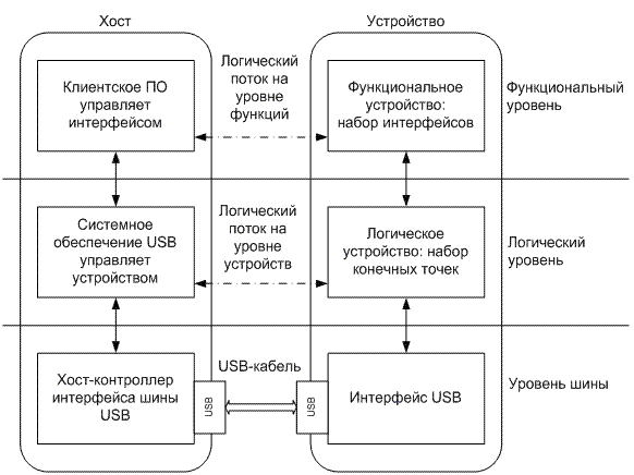
Bus level, logical, functional ... These, of course, are wonderful abstractions, but they are more likely for those who are going to make a driver or application software for the host. On the side of the microcontroller, I expect a templated state machine, in the nodes of which we usually embed our useful code, and it will be buggy by all laws of the genre first. Or software on the host will be buggy. Or a driver. In any case, someone will be buggy. MK libraries are also not easily understood. And now I look at the traffic on the USB bus with the analyzer, where the events in an unfamiliar language with three wonderful levels do not fit at all. I wonder if I have such a dissonance from the flu fever in my head?
If the reader had similar feelings, I propose an alternative, which appeared to me unexpectedly clear in an overheated brain vision of the USB stack, based on the favorite 7-level OSI model. I limited myself to five levels:
I do not want to say that all software and libraries are already made or should be designed based on this model. For engineering reasons, code with levels will be very mixed. But I want to help those who begin their acquaintance with the USB bus, who want to understand the device exchange protocols and domain terminology, get closer to the ready-made examples, libraries and better navigate them. This model is not for upload to MK, but to your brilliant minds, dear friends. And then your golden hands will do everything themselves, I have no doubt :)
So, let's go, correct if you see the jambs. This is a draft version, and if this has already been drawn somewhere, please forgive me, I did not find it and therefore twisted it myself. I think the picture will not run away, but for now I will explain to the venerable public why I have taken up this publication.
Another flashback from the nineties
I shook out my first bug from someone else's code in the late nineties, being a student at part-time jobs. It was pppd under FreeBSD, which we then screwed onto the modem pool. Motorola modems stuck in the end, no one could get through, the line disappeared in vain, and the only remaining way through PPP keep-alive was somehow buggy. That's when I found out that pppd for some reason is waiting for six LCP response bytes instead of the four. Then I felt like a dashing buzzard from the nineties :-) What does PPP have to do with it? It just looks like USB: batch and point-to-point. True, unlike USB 2.0, full duplex.
Whether we like it or not, the evolution of microcontrollers is clearly not going to stand still. No, no, and it flickers in the publications ( http://habrahabr.ru/post/208026/ , http://habrahabr.ru/post/233391/ ) "heavy peripherals" - USB bus implementations mounted in MK, with parsing examples using HID and the like. We must pay tribute to the author of RaJa : out of eight examples cited in the standard library STSW-STM32121 (UM0424) and somehow documented , he chose the most useful (Custom HID), ported it to the free Em :: Blocks environment, outlined it in a clear language, a little embellished, bravo! It saved me a ton of time.
How to get to the library?
Having received the RHIDDemo project for Em :: Blocks, kindly posted by the author on GitHub , I started porting it to Keil (my FTDI-based CoLink debugger; someone, tell me the Coocox plugin for Em :: Blocks). But I just couldn’t understand: where the hell did the author get SPL 3.6.1 of the 2012 release if 3.5.0 from 2011 was posted on the site? I went through a rather boring quest, which, to my surprise, led ... right to the finished Custom HID project for Keil as part of the USB FS 4.0.0 library. It lies in plain sight of everyone, like a mouse under a broom. Well, okay. But I finally smoked STMicroelectronics releases, found a description of the USB FS STSW-STM32121 library (UM0424)and thwarted the developer’s attempt to drive me crazy. Tell me, it’s normal to put the vintage CMSIS 1.30 of the 2009 sample into the 2011 SPL 3.5.0 set, the new 2012 SPL 3.6.1 release to hide in the USB-FS 4.0.0 2013 release (putting the CMSIS 3.0.1 from 2012 in the same place), despite the fact that they also posted the current version of CMSIS 3.30 release 2014? By the way, in SPL 3.6.x for STM32F10X a couple of USART bugs were fixed regarding buffer overflow signals. Thanks, though release notes left ...
HID vs SNMP
So, taking up the STM32F103C8T6, I also decided to move a little on the topic of USB HID, it painfully well abstraction USB HID fits into the concept of all sorts of sensors, sensors and other PWM-controlled power drivers. Something reminded me of SNMP, only in a very simplified form: HID descriptors play the role of SNMP MIB. When the device is initialized by the host: “Hello host! I am a coffee maker. I have a [start] button, [cream], [sugar] knobs, [coffee residue], [water residue], [sugar residue], [cream remaining] sensors. Tighten the driver, push the button, drink some coffee. ” Doesn’t resemble anything? An example of an SNMP conversation: “Well, hello, a management station with software for $ 100,000. And I’m the switch chassis for $ 200,000, and 4 more modules at $ 100,000 apiece are sitting on me; each has 16 more ports with indecent speed, and all the functions here simply can’t be listed ... ask separately for each item; oh yes, the processor load is such and such, there are so many memory ... ". And another dozen pages in the same vein.
I liked the idea of HID. But as soon as I went out of Windows beyond the learning tasks of blinking LEDs (forward to the real UNIX environments!), I started to go through all the unfinished slots , and I felt like some kind of helpless lamer. While debugging the project, I instinctively grabbed some kind of tcpdump (it’s called: usbdump (8) , or usbmon ), but I saw only messages in an unfamiliar language.
It became obvious: there is not enough fundamental knowledge about the USB bus. If the OSI model and the TCP / IP stack, any third-party IT person is aware somewhere at the level of the spinal cord just by force of necessity, then with USB the situation is different. It is understandable: there you can (need) to spy traffic through the same tcpdump and configure the hardware with software, and then full plug and play, and you can fix something by updating the driver or firmware (or reinstalling the OS). But you and I all gathered here just to make good firmware, right? After reading some of the USB descriptions on the network, I was surprised how confusing the documentation might be. I even got the feeling that they specifically want to lead us astray, letting go of the fog and getting rid of competition in the bud. I do not agree with this state of affairs!
Another great scheme
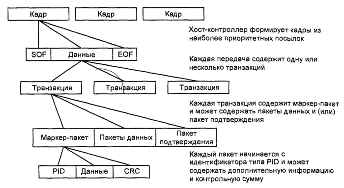
In the vastness of the network I met another illustration (it was in BMP format, no kidding):
At first it looks optimistic. Finally, the stack is unassembled. The frames, however, are marked poorly: I would draw them with vertical dashed lines, and EOF is just a pause, the data is not really transmitted. But we begin to read the context and
The USB bus host controller creates frames ;And one more thing:
Frames are transmitted by serial bit transmission using the NRZI method.
each frame consists of the highest priority premises , the composition of which forms the host driver;
each transfer consists of one or more transactions;
each transaction consists of packets ;
each packet consists of a packet identifier, data (if any) and a checksum.
It seems that everything is drawn correctly, but as you read the questions, it becomes more and more. Is the minimum transmitted data structure on the bus - is it a frame or packet? In general, is it necessary to look from top to bottom or vice versa? And what is encoded using the NRZI method - frames, packets, or just the entire bitstream on the bus? Transaction consists of sending, transferring, or maybe a valuable parcel of what?
Why not just: does the host group the packets into transactions and distribute them according to time slices, called frames, to give priority to time-critical data (video, audio) based on the current bus bandwidth? Yes, there are some nuances in USB with scheduling packet transfers; I don’t touch them yet.
My vision of the USB stack
I consider as good documentation USB hub in a NutShell mentioned here (cheers, translation ), as well as USB Made Simple . Using them, I collected my version of the USB stack, I will draw it again.
Physical level
At the physical level, a set of electrical modes of a differential pair of conductors (together with ground) is used to indicate the states by which the bitstream is encoded using the NRZI method with bit stuffing : here, after six consecutive “1” (well, I wanted to say, say , 0xffff) "0" is inserted so that the receiver does not stick for a long time in one state; uzn receiver andIf the inserted “0” is inserted and it does not count the data, this is a fairly common coding technique for better frequency self-tuning. A pair of wires together with the ground makes it possible to form at least four static states (they are denoted by J, K, SE0, SE1). In USB 2.0, SE1 is not used, and the three remaining ones are additionally played in dynamics (with clocks and transitions) to transmit several more control characters (packet boundaries, reset, connect / disconnect, power saving / output). Good illustrations are in USB Made Simple, Part 3 - Data Flow .
Those. as a result, data is transmitted in the form of zeros and ones, plus any control characters so that you can prepare normal data packets from all this electrodynamic kitchen.
(supplemented at the request of readers)
Batch level
At the packet level, addressless packets are transmitted between the host and the device (a pair of devices on a half-duplex line can do without addressing). The package consists of a SYNC token to synchronize the receiver clock, a byte sequence, and an EOP character. The length of the packet is variable, but negotiated through the upper levels of the stack. The first byte is called Packet Identifier (PID), it has a simple redundant format for noise immunity and is suitable for feeding the next level machine (for assembling transactions from packets). Packets with stuffing (longer than one PID byte) are provided with a checksum (short CRC5 or long CRC16, depending on the type of packet). The protocol analyzer should at least show us the packets.
Transaction rate
At the next level , transactions are collected from packages . A transaction is a small set of packets (in Full Speed USB 1, 2 or 3) that follow strictly one after another, which (in half-duplex mode) the host exchanges with the endpoint, and with only one. It is very important that only the host opens the transaction, this is the specificity of USB (we have less trouble in the MK firmware). At the transaction level, you can talk about the channel (pipe) between the host and one of the end points of the device, but I deliberately avoid the term "data link layer» (Data Link) of the OSI model. The protocol analyzer should at least decode transactions.
Gear level
On top of the transactions, place the transfers level. There are four types of them in USB: control with endpoint No. 0 (control transfers), interrupt transfers, isochronous transfers and bulk transfers. The last three are options for stream pipes, about which I will also say a few words. This level should also display a good protocol analyzer.
Application level
Crowns the stack, as usual, the application level. Here, things happen: setting the address for the device by the host, telling the device about itself in the descriptor language, host commands to select the configuration (control transmissions), exchanging data with HID devices (I have found interrupt transmission in the examples, I want to try the control), printing to the printer and scanning, access to a USB drive (large-block), communication through headsets and webcams (isochronous) and many other wonderful things.
Finishing touch
Having run down the levels for a second, we can add that the host periodically throws the same Start of Frame (SOF) packets on the bus, breaking the time into equal intervals, but so as not to break the transactions themselves. Therefore, SOF packets can be considered independent transactions. Do not confuse the USB frame (frame) with the OSI model of the link layer. It’s better to recall the frames (frames) of an audio CD, it’s just a quantum of time: the host “ticks” the bus with SOF packets so that the connected devices plan ahead to participate in the so-called isochronous transmissions chasing streams of data in real time. Well, or like this: transaction groups are planned by the host at time intervals called frames. The frame is 1ms at Full Speed and 125mks at High Speed USB, but High Speed is a more complex standard, it is better to study it separately.
UPD:
A good question was asked by readers: what about fragmentation? I did not find in USB 2.0 signs of fragmentation at the transaction level and below, i.e. transactions for this is to be transferred in its entirety. In some cases, transfers can and should be divided into several transactions, especially taking into account isochronous modes. And I repeat that so far the host is in charge of all planning (on the MK side we have to think less).
We look at USB traffic
A good selection of illustrations can be found in the aforementioned USB Made Simple book, chapter 5: www.usbmadesimple.co.uk/ums_5.htm
Here is one of them
So, the transaction is always initiated by the host in relation to one selected endpoint on the device (in addition to a special point with number 0, there can be up to 15 more on one device, for example, a combination keyboard with a mouse, thermometer, flash drive, coffee maker and
If the host receives data from the device, the latter cannot open the transaction itself, but can only wait for the right moment and participate in it. The host opens the transaction to the device with a packet with PID = IN (Token group) and guarantees bus freedom for the right time, the device throws a packet from the Data group, depending on the type of transaction, the host can confirm success with the third packet from the Handshake group (ACK, NAK, STALL, NYET ), the transaction is closed.
When sending data to the device (PID = OUT, Token group), the host opens a transaction, sends a packet with data (Data), and depending on the mode, it can receive a Handshake packet confirming the success of the transaction.
At the end of the transaction, everything will return to normal, the device will again wait for control packets from the host.
USB Transfer Modes in STM32 USB FS Examples
So that one pair of wires can drive copying from a disk simultaneously with an audio-video stream, mouse gestures and a high-speed oscilloscope signal, there are different types of messages and transmissions.
Just above I just described a simple streaming channel(Stream Pipe) between the host and the endpoint, where the packets with the filling (Data groups) do not carry any special or control information to the USB subsystem itself. Complete freedom of correspondence, the controller library should provide primitives for downloading a buffer of arbitrary size from the MK memory to the host or vice versa. Cutting packets, forwarding and "defragmenting" let the MK library be paired with the host driver. In STM32, these are USB_SIL_Write () and USB_SIL_Read (), described in UM0424. They are the very logical level of abstraction. On the host side, see the description of the corresponding driver (for example, in FreeBSD it is ugen (4) ).
However, I consider the use of heavy peripherals such as USB to organize a simple streaming channel blasphemy (one wonders: what did the USART not please?). But situations, of course, are all sorts.
In any case, in order for the USB subsystem to come to life and the device to be determined, an exchange of control transactions is required.
DISCLAIMER
Further examples will be mentioned from the same UM0424 library for working with Full Speed USB from STMicroelectronics, but they are designed for their native demo boards. Take an example from the author of Raja , be engineering savvy in adapting projects to your demo payment.
Everything is clear with the software: these are examples not for industrial use, there may be bugs, some parts (such as the link table in the Mass storage example) are protected by a patent, and you do not have the right to use them in a commercial project. But that's nothing, the Chinese then manage to sell USB products on the market, in which even the library VID and PID did not bother to change.
For iron, as I understand it, we must start with quartz. I have a Chelyabinsk PinBoard II with 12 MHz quartz (all libraries are sharpened under 8 MHz), I changed the PLL multiplier from 9 to 6 ( link with explanations), otherwise the MK will accelerate to 108 MHz instead of 72 MHz, and USB to 72 MHz instead of the set 48 MHz will not go at all. You can also reduce the MK speed to 48 MHz by changing the USB bus divider from one and a half to one. Specialists do not like to use the internal MK HSI generator : the frequency can slightly float away from heating, I find it difficult to predict the consequences for USB. Well, do not forget about the periphery, of course. Without the SPI / SDIO flash memory from the Mass storage example, you can only do the analogue of / dev / null, but you will format the hell out of it :-)
Test transmission and message channels
Thinking about USB, I recall the good old PPP protocol with its LCP , IPCP , CCP, and more xcCP . Exchange of a host with an endpoint No. 0 of a special kind of messages is the local equivalent of xзCP.
Through control transmissions, the device is initialized, receives an address, tells the host about itself in the descriptor language (so that it finds and activates the desired driver). Without control operations, simple streaming will not “go”, if the device does not respond in form, the host will soon shut down the port: the protocol must be observed.
In principle, the protocol does not prohibit the interchange of data at control point No. 0, similarly to interrupt mode. At the same time, think: how will you update the MK firmware, so to speak, in the field? Ready to keep the programmer? There is another solution.
Example: Device firmware upgrade
Interrupt Transmissions
This kind of ( interrupt transfer ) is intended for the exchange of small transactions, similar to the control ones. No, the device cannot interrupt the host, it is waiting for a poll, their frequency and packet sizes are specified in advance in the device descriptor. Well suited for all kinds of remotes, sensors, sensors, mice, LEDs and other HID coffee makers. A channel with interruptions of each point is unidirectional.
Examples: Custom HID , Joystick mouse , Virtual COM port
Isochronous Transmissions
Χρόνος in Greek means "time." Isochronous transfer ( Isochronous transfer ) - the local tech that allows to manage data flows in real time. It features a guaranteed (but not necessarily wide) bandwidth and the absence of confirming transactions, almost like UDP with QoS. Broken package? This is the god Chronos pushed MK on the foot. Do not try to send the packet again, otherwise God will be upset. Checksum, however, we check quietly from Chronos. Isochronous transmissions are good for real-time audio-video and measuring systems, as well as other dual-use toys . Although some of them may it’s more interesting to hang some kind of AVR by connecting it to our ARM using USART or SPI. Isochronous operations are involved in frame signaling (recall the ticking SOF packet).
Example: USB voice speaker
Large block transmissions
No, we won’t carry bags of cement. I think everyone has learned the mode of operation of all kinds of USB drives. Bulk transfer transmissions are intended to send data as much and faster as possible, always with the forwarding of broken packets, but without bandwidth guarantees, giving way to isochronous transmissions if necessary (as in TCP without QoS). I already talked about the internal device of USB flash drives , now you can download and run the current prototype. I have not tried it myself, but the SCSI command table in the description of the example (as it were, by the way) quite symbolizes. I did not find signs of a wear management algorithm for NAND-memory :-)
ATTENTION: in some places the patent protection STM applies.
Example: Mass storage
What remains unsolved
I do not have the goal of creating another USB tutorial, there are enough of them without me, and they are well described there: the electrical part, protocol details, work with hubs, descriptor language and HID abstraction level, problems with the uniqueness of VID / PID, USB 3.0 and many other great features of the USB bus, both useful to us and not so. IT people especially recommend an excursion to the dark side with an overview of enemy devices (a flash drive with a disguised HID keyboard that will do scary things).
References
Adapting the Custom HID example to the free Em :: Blocks environment and the low-cost demo board STM32F103C8T6 manufactured by LC-Tech : habrahabr.ru/post/208026
Battle for the UPS: habrahabr.ru/post/233391 another battle for the UPS: habrahabr.ru/ post / 233391 / # comment_7944489
Excursion to the dark side (spy device from AVR): habrahabr.ru/post/153571
Instructions for USB analysis in Wireshark for Windows and Linux: wiki.wireshark.org/CaptureSetup/USB
USB book in a NutShell: www.beyondlogic.org/usbnutshell/usb1.shtml
USB in a NutShell Translation: microsin.ru/content/view/1107/44
USB Made Simple Book (really simplified): www.usbmadesimple.co.uk
STSW-STM32121, STMicroelectronics USB full speed device library and all the examples mentioned (UM0424) www.st.com/web/en/catalog/tools/PF258157
P.S.
Reading publications on the Habrir, dedicated to one degree or another microelectronics, I discerned two engineering castes, we will call them conditionally: Promelectronshchiki and Aishishniki . This is a kind of engineering Yin and Yang, in each of us there is a share of both.
Industrial engineers have brilliant knowledge and skills in iron, they solder radio parts the thickness of a hair with their left hand with their eyes closed (and then it works). Having looked at the electronic circuit, almost physically they begin to sense all its currents with potentials, they also work with power circuits, and with (large, fast, dangerous) industrial products. The MK programming approach is appropriate: it just needs to give the right logic levels to the right legs at the right time, not so important in what way. Conservative in technology (don’t fit - it works), MK heavy peripherals are not particularly favored. When discussing object-oriented programming, information security, giant projects with a million lines of code and all sorts of sophisticated graphical interfaces get bored. Instead of a packet-oriented USB bus, they prefer USART streaming,
IT people are brought up on an understanding of operating systems, network infrastructure and complex interactions, the elite is well-versed in information security and versed in all sorts of invisible ways to penetrate someone else's system. At the same time, some people love cats very much (how can you not love them? I really don’t hold, I don’t breed and I don’t cook :-). Many love freedom of information, scolding corporations / governments, and defeating the forces of nature with the power of thought. Pathologically lazy, but they adore new technologies and twisted engineering puzzles with expensive toys (preferably solved at the software level or, in extreme cases, jumpers). Relations with the soldering iron are wary: do not ask the IT specialist if he likes the soldering iron, he may misunderstand; better ask if he likes to solder electronic circuits.
Why am I? We just see this world in different ways ... After all, the Linux kernel was built by the same guys, from C modules and assembler inserts for specific platforms, and they seemed to do without holivars. I see a truly serious project as a multi-core system combining the most modern MKs with heavy peripherals, but I can’t exclude links with classic models such as AVR: they can weigh some critical, fast-moving cutting edge of technical progress. If the code has been tested for years, then why not?