“How I, as an ordinary student, designed and assembled my 3D printer model”
Many of us are accustomed to watching the progress and the latest achievements of technology and science, as if a little from the outside - evaluating specific products, and not the process itself. However, a student from Volgograd, Mikhail Kozenko, is not one of them. He is just the one who personally prefers to go all the way from the idea to the final result. And the result of his searches was a 3D printer, which brought several awards to the young inventor (in May he turned 15 years old).
We met Misha by chance - the news about his printer appeared on several sites, followed by radio invitations, and there were a couple of posts in entertainment groups (Misha, by the way, brought a lot of disappointments due to overly ironic comments from the public). In our group "VK"Misha also had news. And, surprisingly, the author himself, without our invitation, entered into a dialogue with readers of the “Simple Science” public, explained, prompted and taught. He, like us, with his book for children 5-12 years old “Simple Science” , moves science forward not just with words, but with concrete deeds. So we came up with the idea to make a detailed post for "dummies" (by which I mean myself, not respected Habrovsk citizens), how to make a 3D printer from scratch.
Further, according to the author, who will be happy to participate in the discussion under this post. And if the text turns out to be useful and interesting, he will talk about creating a “second version” of the printer.

So, I’ll start my story with the fact that I like to make and create interesting things. And a few years ago, I seriously became interested in 3D printing, because a 3D printer is a device for the quick manufacture of artifacts, and in the hands of a person with imagination, a whole factory. I became interested in this technology, learned about the RepRap project , the main task of which was to make 3D printing available, it was thanks to it that most of the cheap models appeared. I saw that people assemble printers, and, in principle, this is nothing complicated. Then I decided that I was simply obliged to purchase or assemble such a device for myself!
Thus, I had only the desire and financial support of my parents, whom I told about my goal. It took me about a year to understand printing technologies, design and some designs. Now the most important thing was coming. To begin with, I decided that I need a printer that works on FDM technology (fusion simulation), it is the most common and simple, the material and details are easy to find, and besides, there are already experienced people in this field. Then it was necessary to decide in what form I should buy a printer, maybe buy a finished device or a complete set of parts, or maybe assemble my own? I didn’t really like the ready-made solutions, so I decided that you can buy electronics and mechanics, assemble a temporary frame first, and print the details on the resulting device already to a normal printer.
I decided that for the “zero model” guiding shafts from old printers with a diameter of 8 mm would go, it’s good that we had a lot of them in the garage, and the bushings can be cut from an 8/10 aluminum tube, which has a slightly smaller inner diameter than 8, and then just squander it so that it fits snugly and glides easily. There were a lot of chipboard in the garage, and I decided to make a frame out of it. I decided to buy everything else (namely, electronics and mechanics) on EBay in China. I chose Arduino Mega 2650, Ramps v1.4, 4 drivers A4988 (although I bought 5 and then did not regret it), 5 stepper motors of the NEMA 17 form factor, with a torque of 4 kg * cm (I took it with a power reserve just in case) , 400 W power supply unit for 12 Volts and 33 Amperes, Mk2A heating panel, with glass, which, unfortunately, did not reach the whole, an all-metal thermal head of the Bowden Hot End type, 1 m Teflon tube for a thermal head, a monitor already for a second printer, and even small things, two 29-tooth pulleys and a couple of meters of gt2 belt, a couple of couplings, a feed wheel with teeth for an extruder, a couple of 30x30 small fans, a couple of pneumofitting fittings for an external tube with a diameter of 4, 3 limit switches, as well as 20 pieces of 608 bearings, since this came out cheaper than in Volgograd. All this cost about 20k.
While the details went on, I started designing, not trying with a detailed study and using only dimensions, in a week I created a project for my printer model, which, without hesitation, I called VolgoBot.

The overall project of my printer made in CAD COMPASS 3D Home
I decided that it would be a cube assembled from chipboard. Electronics will be placed on the right side wall, and a coil with plastic and a feeder on the left side. It will have three tiers: the lower one will carry out only the bearing function, the middle one will carry the Z carriage, and all the mechanics will be concentrated on the upper one: the Z axis engines and the H-Bot positioning mechanism, which I chose because of its obvious advantages. There is only one belt in it, which means that the tensioner is also needed one, there are only 2 fastenings for the ends of the belt, and in general, in this mechanism all the engines are on the frame, which facilitates the carriage, and as for the firmware, then in the standard Marlin to activate it you need to uncomment only one line of #define CoreXY, well, and correctly invert the axis.

The circuit for connecting electronics to Ramps v1.4, as you can see, there is nothing complicated.
When I became confident in my project, hell began for everyone who lives nearby, since for about two weeks I worked with a jigsaw, an electric drill, a hand tool on the balcony. Every day, from morning to evening. Some details simply did not work out the first time, I had to make some changes to the design and redo them. And finally, all the original parts for the printer were ready!
Without wasting time, I proceeded to configure the firmware. I won’t take up much space here with the setup instructions, I’ll say that I used thisarticle, everything is very clear, clearly and clearly described. Only it is necessary to pay attention to the fact that for my printer it is necessary to uncomment the line #define CoreXY, which I already spoke about.
And so, the components from China came, as it turned out, not quite successfully, the Teflon tube did not come, but instead they sent two more pulleys and 3 meters of the GT5 belt, I did not sort things out. And so I had to order in a domestic store.

Almost everything to build is
And while the phone went on, I began to put everything together, it wasn’t particularly difficult, the most important thing is to fulfill some requirements so that everything is fixed very firmly and reliably, and the guides are parallel so that the carriages do not jam, and, in general , it follows that the axes themselves are perpendicular. So, the printer was completely ready, with the exception of the Teflon tube.

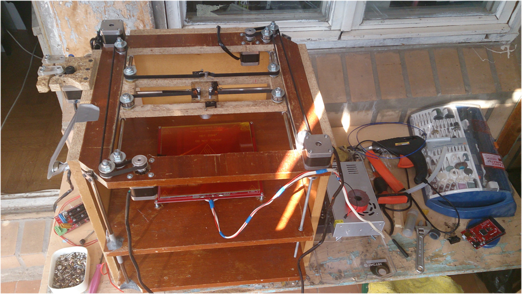
The assembled H-Bot
In the process ...

So, we are waiting for the bowden handset.
I really was eager to try it out and I decided to set up the systems for now and print later when the handset is on. At the first connection, everything almost burned out, I found that it was a faulty stepper motor driver, it had poor soldering.

Lubricated soldering nearly ruined the whole thing
I replaced it, and then everything connected well, then, of course, I fixed the defect on this driver and left it spare, but it was up to the setup! I downloaded the already prepared firmware via the Arduino IDE to my printer, connected to it through the Repetier-Host, and issued the first commands. It turned out that some axes were mixed up and they had to be inverted in the firmware. It was already evening, and I did not begin to do this, and in the morning, with a fresh head, I quickly figured out the problem, set it up correctly, reflashed it, and again tried to issue commands. This time everything worked more or less well, but sometimes the motors did not have enough power, then I adjusted the current strength using variable resistors on the stepper motor drivers. And so! All the teams went right, it turned out even from the first attempt to correctly calculate the steps of the engines, their speed, and that's all! It only remained to try to print, but the tube was still gone. Therefore, I had to make a very stupid decision: let the printer print, and I will feed the plastic rod manually, about as much as the extruder feeds. Although this is very stupid, but the first print of the puck and the pendant for the parents didn’t get as bad as a souvenir, after several such tests I trained and served quite cleverly.

The first seal. Parents asked to make
Hurray! The phone came, I put it on, but the seal didn’t want to advance into anything. The fact is that instead of a gear wheel, I decided to use a rubber one, and it just slipped, since I had a real one, and I quickly designed another feed mechanism and spent about an hour printing. And again: the printer was printing, and I was delivering plastic, this time through the handset, but it worked out pretty well. I assembled a new extruder without problems, reflashed the printer under a new feed wheel, and not this time everything worked just fine!

The first extruder. A dinosaur, isn't it?

Version # 2 of an extruder with a conventional feed wheel.

Second extruder. As it turned out, the extra spring
First I tried to print a bust of Lenin, then a well-known model of an owl, now I tweaked the settings a little and printed another owl, this time I was quite happy with the quality!

The first real seal, nozzle 0.5, layer thickness 0.4

The second real seal, nozzle 0.5, layer thickness 0.4

Reprinted owl, this time nozzle 0.5, layer 0.3
Thus, VolgoBot 0.0 was completed and completely ready to print parts for VolgoBot 0.1, which I already, without wasting time, began to design!
Here, by the way, is a video on VolgoBot 0.0:
My article is, rather, not a story about some kind of school genius who invented a bicycle, but simply proof that if there is a desire and a little money, everyone can assemble a 3D printer! To implement my project I needed:
1. Desire and clear goal to get a 3D printer as a result
2. Time to study the topic and open RepRap project (I spent a year)
3. Some amount of money (for my project it took about 23 thousand rubles)
4. Good CAD and the ability to work in it (I used the home version of KOMPAS 3D)
5. Design time (I needed a week)
6. Time to create the printer itself (I needed 2 weeks)
7. Time to set up the printer itself (I needed a week)
If this article is of interest, then in the next part I will talk about creating VolgoBot 0.1 already. If there are objective comments and criticism, I will be glad to listen, since I am writing material for HabrHabr for the first time. In the meantime, here is the layout geometry for the second printer model: The

layout geometry of the printer, Volgobot 0.1, which has not yet been completed
We met Misha by chance - the news about his printer appeared on several sites, followed by radio invitations, and there were a couple of posts in entertainment groups (Misha, by the way, brought a lot of disappointments due to overly ironic comments from the public). In our group "VK"Misha also had news. And, surprisingly, the author himself, without our invitation, entered into a dialogue with readers of the “Simple Science” public, explained, prompted and taught. He, like us, with his book for children 5-12 years old “Simple Science” , moves science forward not just with words, but with concrete deeds. So we came up with the idea to make a detailed post for "dummies" (by which I mean myself, not respected Habrovsk citizens), how to make a 3D printer from scratch.
Further, according to the author, who will be happy to participate in the discussion under this post. And if the text turns out to be useful and interesting, he will talk about creating a “second version” of the printer.
So, I’ll start my story with the fact that I like to make and create interesting things. And a few years ago, I seriously became interested in 3D printing, because a 3D printer is a device for the quick manufacture of artifacts, and in the hands of a person with imagination, a whole factory. I became interested in this technology, learned about the RepRap project , the main task of which was to make 3D printing available, it was thanks to it that most of the cheap models appeared. I saw that people assemble printers, and, in principle, this is nothing complicated. Then I decided that I was simply obliged to purchase or assemble such a device for myself!
Thus, I had only the desire and financial support of my parents, whom I told about my goal. It took me about a year to understand printing technologies, design and some designs. Now the most important thing was coming. To begin with, I decided that I need a printer that works on FDM technology (fusion simulation), it is the most common and simple, the material and details are easy to find, and besides, there are already experienced people in this field. Then it was necessary to decide in what form I should buy a printer, maybe buy a finished device or a complete set of parts, or maybe assemble my own? I didn’t really like the ready-made solutions, so I decided that you can buy electronics and mechanics, assemble a temporary frame first, and print the details on the resulting device already to a normal printer.
I decided that for the “zero model” guiding shafts from old printers with a diameter of 8 mm would go, it’s good that we had a lot of them in the garage, and the bushings can be cut from an 8/10 aluminum tube, which has a slightly smaller inner diameter than 8, and then just squander it so that it fits snugly and glides easily. There were a lot of chipboard in the garage, and I decided to make a frame out of it. I decided to buy everything else (namely, electronics and mechanics) on EBay in China. I chose Arduino Mega 2650, Ramps v1.4, 4 drivers A4988 (although I bought 5 and then did not regret it), 5 stepper motors of the NEMA 17 form factor, with a torque of 4 kg * cm (I took it with a power reserve just in case) , 400 W power supply unit for 12 Volts and 33 Amperes, Mk2A heating panel, with glass, which, unfortunately, did not reach the whole, an all-metal thermal head of the Bowden Hot End type, 1 m Teflon tube for a thermal head, a monitor already for a second printer, and even small things, two 29-tooth pulleys and a couple of meters of gt2 belt, a couple of couplings, a feed wheel with teeth for an extruder, a couple of 30x30 small fans, a couple of pneumofitting fittings for an external tube with a diameter of 4, 3 limit switches, as well as 20 pieces of 608 bearings, since this came out cheaper than in Volgograd. All this cost about 20k.
While the details went on, I started designing, not trying with a detailed study and using only dimensions, in a week I created a project for my printer model, which, without hesitation, I called VolgoBot.
The overall project of my printer made in CAD COMPASS 3D Home
I decided that it would be a cube assembled from chipboard. Electronics will be placed on the right side wall, and a coil with plastic and a feeder on the left side. It will have three tiers: the lower one will carry out only the bearing function, the middle one will carry the Z carriage, and all the mechanics will be concentrated on the upper one: the Z axis engines and the H-Bot positioning mechanism, which I chose because of its obvious advantages. There is only one belt in it, which means that the tensioner is also needed one, there are only 2 fastenings for the ends of the belt, and in general, in this mechanism all the engines are on the frame, which facilitates the carriage, and as for the firmware, then in the standard Marlin to activate it you need to uncomment only one line of #define CoreXY, well, and correctly invert the axis.
The circuit for connecting electronics to Ramps v1.4, as you can see, there is nothing complicated.
When I became confident in my project, hell began for everyone who lives nearby, since for about two weeks I worked with a jigsaw, an electric drill, a hand tool on the balcony. Every day, from morning to evening. Some details simply did not work out the first time, I had to make some changes to the design and redo them. And finally, all the original parts for the printer were ready!
Without wasting time, I proceeded to configure the firmware. I won’t take up much space here with the setup instructions, I’ll say that I used thisarticle, everything is very clear, clearly and clearly described. Only it is necessary to pay attention to the fact that for my printer it is necessary to uncomment the line #define CoreXY, which I already spoke about.
And so, the components from China came, as it turned out, not quite successfully, the Teflon tube did not come, but instead they sent two more pulleys and 3 meters of the GT5 belt, I did not sort things out. And so I had to order in a domestic store.
Almost everything to build is
And while the phone went on, I began to put everything together, it wasn’t particularly difficult, the most important thing is to fulfill some requirements so that everything is fixed very firmly and reliably, and the guides are parallel so that the carriages do not jam, and, in general , it follows that the axes themselves are perpendicular. So, the printer was completely ready, with the exception of the Teflon tube.
The assembled H-Bot
In the process ...
So, we are waiting for the bowden handset.
I really was eager to try it out and I decided to set up the systems for now and print later when the handset is on. At the first connection, everything almost burned out, I found that it was a faulty stepper motor driver, it had poor soldering.
Lubricated soldering nearly ruined the whole thing
I replaced it, and then everything connected well, then, of course, I fixed the defect on this driver and left it spare, but it was up to the setup! I downloaded the already prepared firmware via the Arduino IDE to my printer, connected to it through the Repetier-Host, and issued the first commands. It turned out that some axes were mixed up and they had to be inverted in the firmware. It was already evening, and I did not begin to do this, and in the morning, with a fresh head, I quickly figured out the problem, set it up correctly, reflashed it, and again tried to issue commands. This time everything worked more or less well, but sometimes the motors did not have enough power, then I adjusted the current strength using variable resistors on the stepper motor drivers. And so! All the teams went right, it turned out even from the first attempt to correctly calculate the steps of the engines, their speed, and that's all! It only remained to try to print, but the tube was still gone. Therefore, I had to make a very stupid decision: let the printer print, and I will feed the plastic rod manually, about as much as the extruder feeds. Although this is very stupid, but the first print of the puck and the pendant for the parents didn’t get as bad as a souvenir, after several such tests I trained and served quite cleverly.
The first seal. Parents asked to make
Hurray! The phone came, I put it on, but the seal didn’t want to advance into anything. The fact is that instead of a gear wheel, I decided to use a rubber one, and it just slipped, since I had a real one, and I quickly designed another feed mechanism and spent about an hour printing. And again: the printer was printing, and I was delivering plastic, this time through the handset, but it worked out pretty well. I assembled a new extruder without problems, reflashed the printer under a new feed wheel, and not this time everything worked just fine!
The first extruder. A dinosaur, isn't it?
Version # 2 of an extruder with a conventional feed wheel.
Second extruder. As it turned out, the extra spring
First I tried to print a bust of Lenin, then a well-known model of an owl, now I tweaked the settings a little and printed another owl, this time I was quite happy with the quality!
The first real seal, nozzle 0.5, layer thickness 0.4
The second real seal, nozzle 0.5, layer thickness 0.4
Reprinted owl, this time nozzle 0.5, layer 0.3
Thus, VolgoBot 0.0 was completed and completely ready to print parts for VolgoBot 0.1, which I already, without wasting time, began to design!
Here, by the way, is a video on VolgoBot 0.0:
My article is, rather, not a story about some kind of school genius who invented a bicycle, but simply proof that if there is a desire and a little money, everyone can assemble a 3D printer! To implement my project I needed:
1. Desire and clear goal to get a 3D printer as a result
2. Time to study the topic and open RepRap project (I spent a year)
3. Some amount of money (for my project it took about 23 thousand rubles)
4. Good CAD and the ability to work in it (I used the home version of KOMPAS 3D)
5. Design time (I needed a week)
6. Time to create the printer itself (I needed 2 weeks)
7. Time to set up the printer itself (I needed a week)
If this article is of interest, then in the next part I will talk about creating VolgoBot 0.1 already. If there are objective comments and criticism, I will be glad to listen, since I am writing material for HabrHabr for the first time. In the meantime, here is the layout geometry for the second printer model: The
layout geometry of the printer, Volgobot 0.1, which has not yet been completed