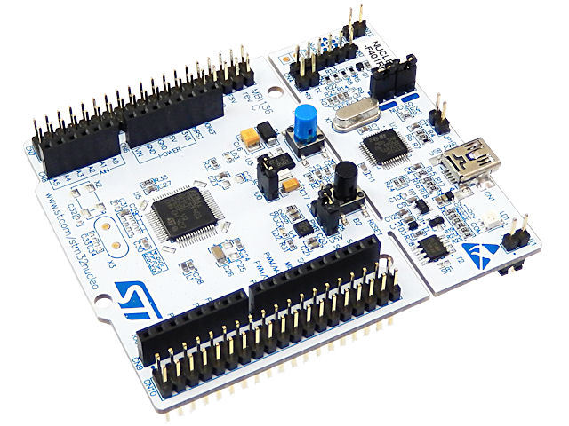
Quick Start ST Nucleo-F401 + Quick Start Guide
In my previous post I tried to briefly introduce you to the ST Nucleo platform.
In this post, I want to tell you, using a living example, some of the strengths of this platform, which has every chance of crowding out the bored Arduino, and show that all code examples and shields from Arduino are great for the Nucleo platform.
Nuleo Platform It is a hybrid of DISCOVERY and Arduino platforms, allowing users to easily use almost all extensions and all code examples for
Arduino. This platform supports MBED.ORG , which eliminates the headache of many beginners in installing, configuring and using compilers for ARM. Almost all existing extensions for Arduino have been imported into mbed.org. In contrast to the already widespread and much-loved platform DISCOVERY, the platform on its board does not have any periphery, such as for example an accelerometer, compass, etc. But the Nucleo platform is designed to make working on it as simple as on Arduino platforms. The platform also has a flexible power scheme (3.3V-5V-7V-12V), a built-in updated ST-LINK / V2.1 programmer for programming any STM32, a built-in virtual COM port (connected by default to USART), a simplified microcontroller programming procedure due to emulation of removable media giving access to the flash memory of the microcontroller.
You can study the features of the STM32F401RE microcontroller yourself, I chose ST Nucleo-F401, due to the fact that at the time of purchase it was the oldest model available, which differs from the others in its higher performance and large memory capacity.
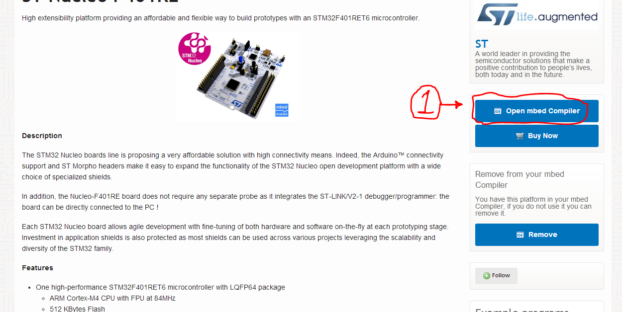
To get started, we need to register on Mbed.org and add the platform we need to our list of devices.
On the Mbed.org website in the section of our platform, at the bottom we can see the link by clicking on which we need to download, install and run:
For the curious, I will try to explain some of the operating modes in more detail:
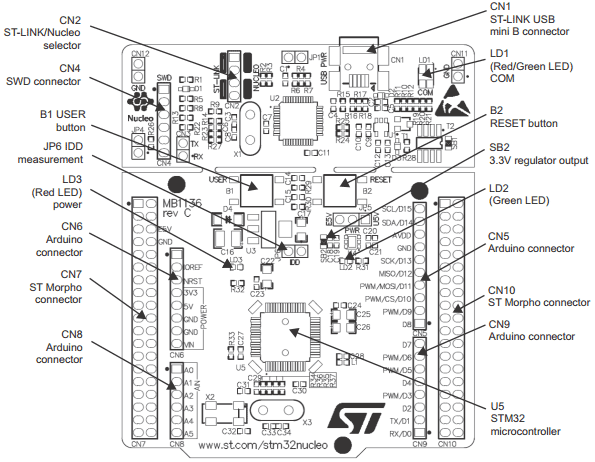
For the rest, it’s enough to remember that there is a JP5 jumper on the board and it has two positions, the microcontroller is powered from USB (U5V position is not more than 300mA) or from an external power source (E5V), for example, from 5 Volts connected to CN7 (the leftmost connector, pin contacts -6 E5V and pin-8 GND). Connector layout
And so we connected and saw that removable media was detected in our computer, this is a sign that everything is done correctly and everything works. You can check whether the microcontroller itself works correctly by pressing the user button, when clicking on it, the flicker frequency of the user LED should change. Having played enough with the LED, let's move on.
Now is the time to create our first program in Embed and flash our controller with it.
I will remove such subsections under the spoiler to save space.
The post was written all night and will soon be supplemented with examples, I want to note that any extensions from Arduino easily fit Nucleo, too, there are no problems with sketches.
In this post, I want to tell you, using a living example, some of the strengths of this platform, which has every chance of crowding out the bored Arduino, and show that all code examples and shields from Arduino are great for the Nucleo platform.
Why is Nuleo-F401?
Nuleo Platform It is a hybrid of DISCOVERY and Arduino platforms, allowing users to easily use almost all extensions and all code examples for
Arduino. This platform supports MBED.ORG , which eliminates the headache of many beginners in installing, configuring and using compilers for ARM. Almost all existing extensions for Arduino have been imported into mbed.org. In contrast to the already widespread and much-loved platform DISCOVERY, the platform on its board does not have any periphery, such as for example an accelerometer, compass, etc. But the Nucleo platform is designed to make working on it as simple as on Arduino platforms. The platform also has a flexible power scheme (3.3V-5V-7V-12V), a built-in updated ST-LINK / V2.1 programmer for programming any STM32, a built-in virtual COM port (connected by default to USART), a simplified microcontroller programming procedure due to emulation of removable media giving access to the flash memory of the microcontroller.
You can study the features of the STM32F401RE microcontroller yourself, I chose ST Nucleo-F401, due to the fact that at the time of purchase it was the oldest model available, which differs from the others in its higher performance and large memory capacity.
Beginning of work!
To get started, we need to register on Mbed.org and add the platform we need to our list of devices.
Instructions for dummies, click to see
To do this, follow the link mbed.org/account/signup and follow the instructions, fill out the registration form.

Select "No, I haven't created an account before" (No, I did not create an account before)
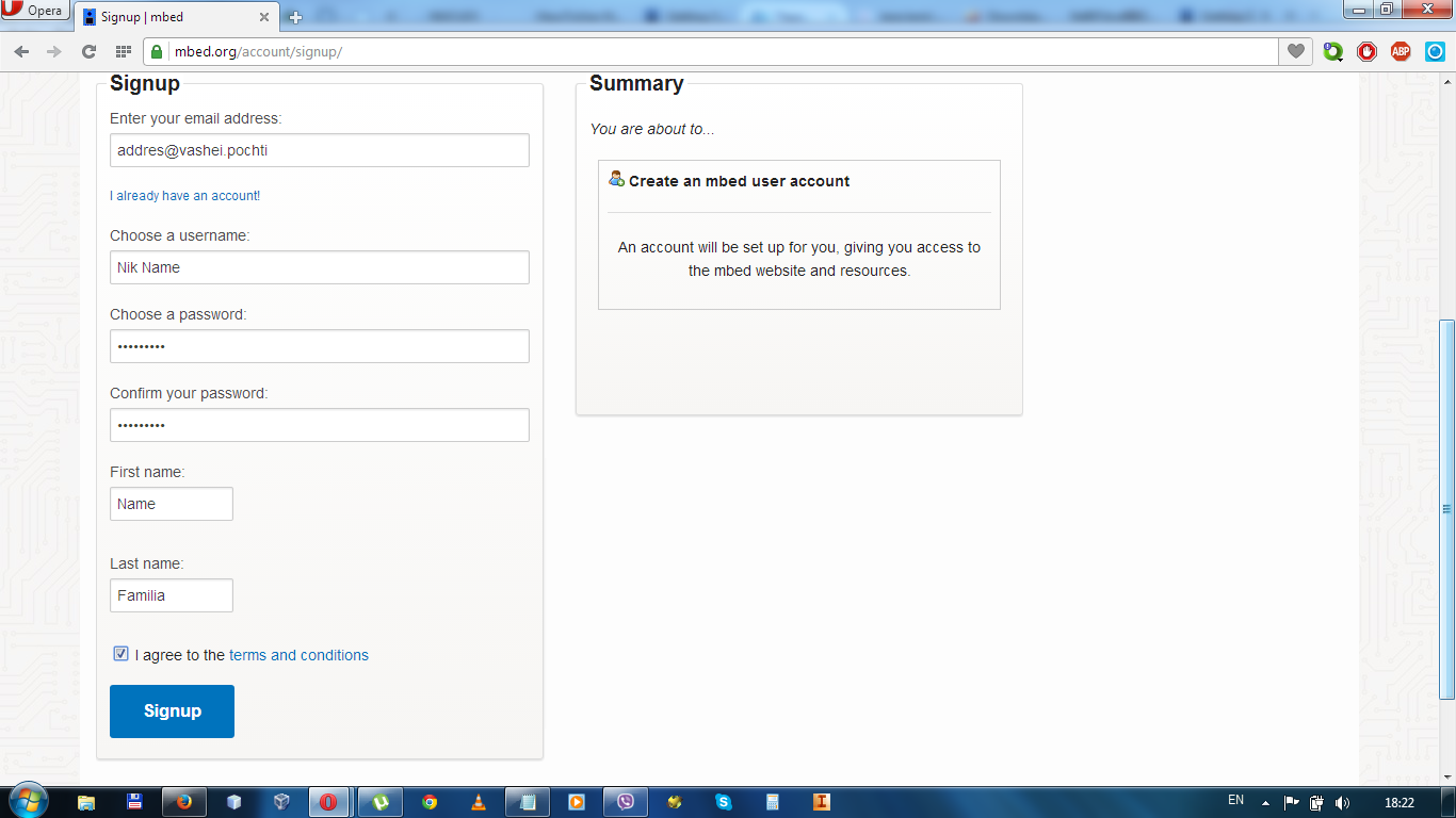
Fill out the registration form and click "SignUp" (Register)
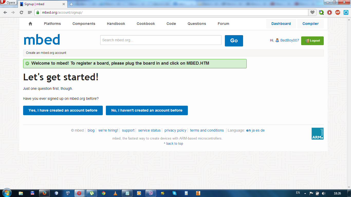
The message "Welcome to mbed!" Should appear To register a board, please plug the board in and click on MBED.HTM ”
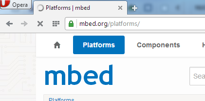
After that, on the upper left, click“ Platform ”and open the list of all platforms supported by the project, and in the list we go to our platform (in our case, this is Nucleo-F401RE).

Having opened the platform description, we find the “Add to your mbed Compiler” button on the left, clicking it we add the selected platform to the list of our platforms.

Now let's click on our nickname (top right) and go to the main page of your profile, here we can see the newly added platform on the bottom right.

Actually, we all registered and added our platform.
Register at Mbed.org
To do this, follow the link mbed.org/account/signup and follow the instructions, fill out the registration form.
Select "No, I haven't created an account before" (No, I did not create an account before)
Fill out the registration form and click "SignUp" (Register)
The message "Welcome to mbed!" Should appear To register a board, please plug the board in and click on MBED.HTM ”
After that, on the upper left, click“ Platform ”and open the list of all platforms supported by the project, and in the list we go to our platform (in our case, this is Nucleo-F401RE).
Having opened the platform description, we find the “Add to your mbed Compiler” button on the left, clicking it we add the selected platform to the list of our platforms.
Now let's click on our nickname (top right) and go to the main page of your profile, here we can see the newly added platform on the bottom right.
Actually, we all registered and added our platform.
Driver Installation
On the Mbed.org website in the section of our platform, at the bottom we can see the link by clicking on which we need to download, install and run:
- first you need to install the USB driver ST-LINK / V2-1 for the programmer, for Windows Vista, 7 and 8 STSW-LINK008 or STSW-LINK009 for Windows XP
- Perform firmware upgrade of the USB-connected programmer ST-LINK / V2-1 STSW-LINK007
Instructions for dummies, click to see
Let's start in order, download the current driver and update the firmware on this page. KLAT
we presumably need two files one " ST-LINK / V2-1 firmware upgrade " the second one is permissible " ST-LINK / V2-1 USB driver on Windows Vista, 7 and 8 "

Unpack the downloaded archives, and proceed.
We start the installation of drivers: in the unpacked archive STSW-LINK008 or STSW-LINK009, run the file under the name stlink_winusb_install for our board (the board is not yet connected via USB).
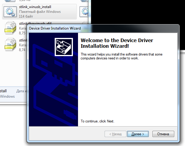
We run this file, which itself will determine the bit depth of the system and the type of installation. We agree with everything, and click yes, then, etc.
Now we can connect our board via USB and see that the LEDs light up and you have decided on a new removable media.
We start the firmware update for our platform programmer:
To do this, connect our debugging platform to the computer, go to the folder with the unpacked STSW-LINK007 programmer update archive and run the ST-LinkUpgrade file.
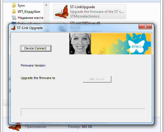
In the window that appears, click “Device Connect”, after finding the device and connecting to it, click “Yes >>>”, the program will do everything and finally disconnect from the device, after that you can close it.
All on this installation of fresh drivers and firmware update is over.
we presumably need two files one " ST-LINK / V2-1 firmware upgrade " the second one is permissible " ST-LINK / V2-1 USB driver on Windows Vista, 7 and 8 "
Unpack the downloaded archives, and proceed.
We start the installation of drivers: in the unpacked archive STSW-LINK008 or STSW-LINK009, run the file under the name stlink_winusb_install for our board (the board is not yet connected via USB).
We run this file, which itself will determine the bit depth of the system and the type of installation. We agree with everything, and click yes, then, etc.
Now we can connect our board via USB and see that the LEDs light up and you have decided on a new removable media.
We start the firmware update for our platform programmer:
To do this, connect our debugging platform to the computer, go to the folder with the unpacked STSW-LINK007 programmer update archive and run the ST-LinkUpgrade file.
In the window that appears, click “Device Connect”, after finding the device and connecting to it, click “Yes >>>”, the program will do everything and finally disconnect from the device, after that you can close it.
All on this installation of fresh drivers and firmware update is over.
Platform Connection:
For the curious, I will try to explain some of the operating modes in more detail:
Information for the curious, click to see. CAUTION!
The board has 3 LEDs.
Three - color LED (green, orange, red) LD1 (COM) provides information on the status of the ST-LINK connection. The color LD1 is red by default. LD1 turns green, indicating that during the connection between the PC and ST-LINK / V2-1, next:
USER LD2 : green user LED, the LED is connected to Arduino pin D13, corresponding to the input / output pin of the microcontroller PA5 (pin 21) or PB13 (pin 34)
LD3 PWR : a red LED indicates that the part with the microcontroller is powered and +5 V is supplied.
B1 USER : the user button is connected to the PC13 input / output (pin 2) of the STM32 microcontroller.
B2 RESET : This button connects to the NRST , and is used to reset the STM32 microcontroller.
Note: The blue and black plastic caps on the buttons can be removed if necessary, for example, when a shield or expansion card is connected on top of the Nucleo. This will avoid pressure on the buttons and therefore the possible constant accidental pressing
Jumper JP6 , marked IDD , is used to measure the current consumption of the microcontroller, to do this, remove the jumper and connect the ammeter.
The ST-LINK / V2-1 in-circuit debugger / programmer only supports SWD for STM32 devices.
Changes compared to ST-LINK / V2:
New features supported in ST-LINK / V2-1:
Features not supported by ST-LINK / V2-1:
Operating modes of the built-in ST-LINK / V2-1:
Pinout SWD:
The STM32 Nucleo printed circuit board platform is divided into two parts: the ST-LINK part and the target MCU part, which can be divided to reduce the size of the board. In this case, the remaining target MCU part can only be powered by VIN, E5V and 3.3V on the ST Morpho CN7 or VIN and 3.3 on the Arduino CN6. However, you can still use the ST-LINK part to program the main microcontroller using the wires between the CN4 SWD and the connectors on the ST Morpho ( SWCLK CN7 pin-15 and SWDIO CN7 pin-13 ).
The power source is supplied either from a computer via a USB cable or from an external source: VIN (7V-12V), E5V (5V) or + 3V3 power pins on CN6 or CN7.
ST-LINK / V2-1 supports the platform via USB, while the programmer itself consumes current up to 100 mA.
The entire STM32 Nucleo board including expansion cards can be powered by ST-LINK USB, provided that the total current consumption does not exceed 300mA (Including 100-mA ST-LINK consumption) when these conditions are met, the red LD3 LED is on and the micro controller is working. If the consumption current is higher, then it is necessary to use an external power source for the entire project or only for expansion cards (not forgetting about the common ground).
When the board is powered by USB (U5V), a jumper must be connected between pins 1 and 2 of JP5 to the U5V position.JP1 jumper can be installed only when the board is powered by USB and the maximum current consumption on U5V should not exceed 100 mA (including all kinds of expansion cards or Arduino Shield).
VIN (7V-12V) or E5V (5V-5.5V) can be used as an external power source in case the current consumption of Nucleo and expansion cards exceeds the permissible current for USB. In this state, you can still use the USB connection for programming or debugging, but first be sure to connect the board to the power source using VIN or E5V, and then connect the USB cable to the PC.
When powered by VIN or E5V, the power-on algorithm must be followed:
If this order is not observed, then the board can be powered first via VBUS and then via VIN or E5V, while the USB port on the computer may malfunction or microcontroller glitches may occur (! The same applies to the reset button!)
When the board is powered by VIN or E5V, the jumper configuration should be as follows:
External power supplies:

(Actually micro manul is over. You can exhale and continue)
Brief technical information from the manual
LED operation modes.
The board has 3 LEDs.
Three - color LED (green, orange, red) LD1 (COM) provides information on the status of the ST-LINK connection. The color LD1 is red by default. LD1 turns green, indicating that during the connection between the PC and ST-LINK / V2-1, next:
- “Slow Flashing Red” / “Off” - when the power is turned on until a USB connection is established
- “Fast flashing red” / “Off” - after the first correct data exchange between the PC and STLINK / V2-1 (connection process)
- “Red LED on” - if the connection between the PC and ST-LINK / V2-1 is established
- “Green on: connection completed successfully or operation completed correctly
- “Flashing red” / “green” - during data transfer. (The firmware process itself)
- “Orange On”: Communication failure.
USER LD2 : green user LED, the LED is connected to Arduino pin D13, corresponding to the input / output pin of the microcontroller PA5 (pin 21) or PB13 (pin 34)
- When the input / output (I / O) value is high, the LED is on.
- When the input / output (I / O) value is low, the LED is off.
LD3 PWR : a red LED indicates that the part with the microcontroller is powered and +5 V is supplied.
Buttons
B1 USER : the user button is connected to the PC13 input / output (pin 2) of the STM32 microcontroller.
B2 RESET : This button connects to the NRST , and is used to reset the STM32 microcontroller.
Note: The blue and black plastic caps on the buttons can be removed if necessary, for example, when a shield or expansion card is connected on top of the Nucleo. This will avoid pressure on the buttons and therefore the possible constant accidental pressing
Jumper JP6 (IDD)
Jumper JP6 , marked IDD , is used to measure the current consumption of the microcontroller, to do this, remove the jumper and connect the ammeter.
- Jumper On: The STM32 microcontroller is powered (default).
- Jumper OFF: the ammeter must be connected to measure the current of the STM32 microcontroller. If there is no ammeter, the STM32 microcontroller is not powered.
Built-in ST-LINK / V2-1
The ST-LINK / V2-1 in-circuit debugger / programmer only supports SWD for STM32 devices.
Changes compared to ST-LINK / V2:
New features supported in ST-LINK / V2-1:
- USB drivers renumbered
- Virtual COM Port Interface via USB
- USB Storage Interface
- USB power manager
Features not supported by ST-LINK / V2-1:
- SWIM interface. (Needed for programming STM8)
- The minimum supported application voltage is limited to 3 V
Operating modes of the built-in ST-LINK / V2-1:
| Jumper Status | Value |
|---|---|
| both CN2 jumpers are dressed | ST-LINK / V2-1 works by programming the microcontroller on the board (default) |
| both CN2 jumpers removed | ST-LINK / V2-1 works by programming the microcontroller via an external CN4 connector (SWD supported) |
Pinout SWD:
| Pin | CN4 | Value |
|---|---|---|
| 1 | VDD_TARGET | VDD for device |
| 2 | SWCLK | SWD beat |
| 3 | GND | Land |
| 4 | SWDIO | SWD data input / output |
| 5 | Nrst | resetting programmable MK |
| 6 | Swo | Not used |
PCB separation
The STM32 Nucleo printed circuit board platform is divided into two parts: the ST-LINK part and the target MCU part, which can be divided to reduce the size of the board. In this case, the remaining target MCU part can only be powered by VIN, E5V and 3.3V on the ST Morpho CN7 or VIN and 3.3 on the Arduino CN6. However, you can still use the ST-LINK part to program the main microcontroller using the wires between the CN4 SWD and the connectors on the ST Morpho ( SWCLK CN7 pin-15 and SWDIO CN7 pin-13 ).
Board power modes.
The power source is supplied either from a computer via a USB cable or from an external source: VIN (7V-12V), E5V (5V) or + 3V3 power pins on CN6 or CN7.
ST-LINK / V2-1 supports the platform via USB, while the programmer itself consumes current up to 100 mA.
The entire STM32 Nucleo board including expansion cards can be powered by ST-LINK USB, provided that the total current consumption does not exceed 300mA (Including 100-mA ST-LINK consumption) when these conditions are met, the red LD3 LED is on and the micro controller is working. If the consumption current is higher, then it is necessary to use an external power source for the entire project or only for expansion cards (not forgetting about the common ground).
When the board is powered by USB (U5V), a jumper must be connected between pins 1 and 2 of JP5 to the U5V position.JP1 jumper can be installed only when the board is powered by USB and the maximum current consumption on U5V should not exceed 100 mA (including all kinds of expansion cards or Arduino Shield).
VIN (7V-12V) or E5V (5V-5.5V) can be used as an external power source in case the current consumption of Nucleo and expansion cards exceeds the permissible current for USB. In this state, you can still use the USB connection for programming or debugging, but first be sure to connect the board to the power source using VIN or E5V, and then connect the USB cable to the PC.
When powered by VIN or E5V, the power-on algorithm must be followed:
- Connect the jumper between pins 2 and 3 of JP5.
- Make sure JP1 is deleted.
- Connect external power to VIN or E5V.
- The voltage at the external power supply is 7 V
- Make sure LD3 is turned on.
- Connect the PC to the CN1 USB connector.
If this order is not observed, then the board can be powered first via VBUS and then via VIN or E5V, while the USB port on the computer may malfunction or microcontroller glitches may occur (! The same applies to the reset button!)
When the board is powered by VIN or E5V, the jumper configuration should be as follows:
- Jumper on JP5 between pin 2 and pin 3.
- Jumper removed on JP1.
External power supplies:
| Power input | Connector Contacts | Voltage | Current | Limitation |
|---|---|---|---|---|
| VIN | CN6 pin 8, CN7 pin 24 | from 7V to 12V | 800 mA | 800 mA if Vin = 7 V, 450 mA if 7 V |
| E5v | CN7 pin 6 | 4.75V to 5.25V | 500 mA |
(Actually micro manul is over. You can exhale and continue)
For the rest, it’s enough to remember that there is a JP5 jumper on the board and it has two positions, the microcontroller is powered from USB (U5V position is not more than 300mA) or from an external power source (E5V), for example, from 5 Volts connected to CN7 (the leftmost connector, pin contacts -6 E5V and pin-8 GND). Connector layout
And so we connected and saw that removable media was detected in our computer, this is a sign that everything is done correctly and everything works. You can check whether the microcontroller itself works correctly by pressing the user button, when clicking on it, the flicker frequency of the user LED should change. Having played enough with the LED, let's move on.
Now is the time to create our first program in Embed and flash our controller with it.
I will remove such subsections under the spoiler to save space.
First program and first programming
На странице своего профиля в Mbed открываем страницу с нашей платформой, дальше используя картинки как помощь, делаем следующие:
(1) Открываем онлайн компилятор
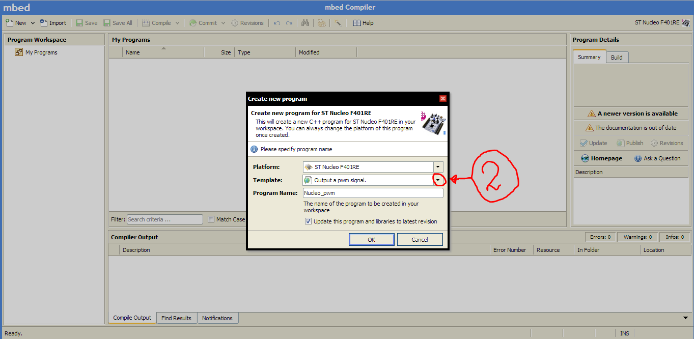
(2-3) Создаем проект под названием „Blinky LED test for the ST Nucleo boards“ и нажимаем „OK“

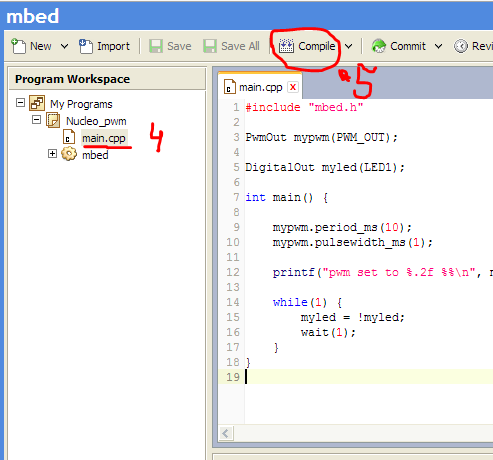
(4 — 5) Открываем и компилируем бинарный файл (5).
После чего нам будет предложено сохранить это бинарник (процедура зависит от вашего браузера). Полученный бинарник мы просто копируем или перемещаем на сменный носитель Nucleo, причем если сразу после копирования обновить содержание сменного носителя то вы его уже не сможете увидеть, что свидетельствует что микро контроллер пере-прошит! (во время прошивки вы увидите как весело мигает светодиод LED_COM)
First program and first programming
Creating a program project in Mbed
На странице своего профиля в Mbed открываем страницу с нашей платформой, дальше используя картинки как помощь, делаем следующие:
(1) Открываем онлайн компилятор
(2-3) Создаем проект под названием „Blinky LED test for the ST Nucleo boards“ и нажимаем „OK“
(4 — 5) Открываем и компилируем бинарный файл (5).
После чего нам будет предложено сохранить это бинарник (процедура зависит от вашего браузера). Полученный бинарник мы просто копируем или перемещаем на сменный носитель Nucleo, причем если сразу после копирования обновить содержание сменного носителя то вы его уже не сможете увидеть, что свидетельствует что микро контроллер пере-прошит! (во время прошивки вы увидите как весело мигает светодиод LED_COM)
The post was written all night and will soon be supplemented with examples, I want to note that any extensions from Arduino easily fit Nucleo, too, there are no problems with sketches.