Solar lanterns - we need brighter

Surely, many have already played enough with the Chinese solar lanterns and become disillusioned with them. Let's try to figure out the question: what is the reason for their low brightness and is it possible to do something about it?
Solar panels
To begin with, let's compare solar batteries of flashlights. I chose three flashlights, the first came from Aliexpress, the second was bought about 3 years ago in the Globe and the third was bought this year in Leroy:
Also three solar batteries with a size of 56.8x56.8 mm and 60x65 mm will take part in comparison:

And 82 mm diameter round solar battery:

I don’t have an electronic load, so the test will be performed using a 1600 mA / h battery with a previously discharged and then charged up to 500 mA / h. With a test test on such three identical batteries of one fully discharged, half-charged and fully charged, the difference in charging current differed insignificantly. Alternately, we connect the multimeter to the rupture of the wire of the flashlight batteries and measure the charge current.
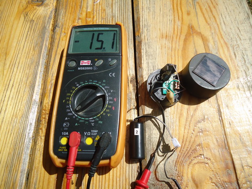
Solar flashlight bought on Aliexpress:

Solar flashlight purchased in Globe:
Solar flashlight purchased in Leroy:

Similarly, we measure the charging current from solar panels by connecting them through a flashlight card to the untimely dead under someone's foot.
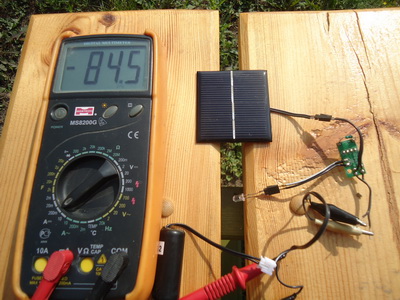
Solar battery 56.8x56.8 mm:

Solar battery 60x65 mm:
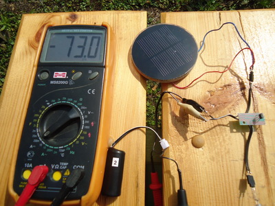
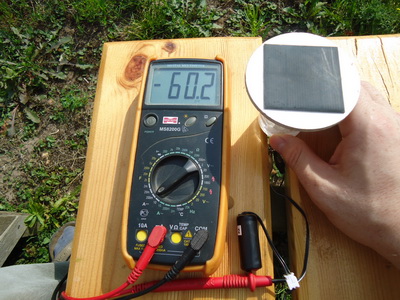
Solar battery with a diameter of 82 mm:
Measurements were usually taken at intervals of one hour, the missing measurement results for the tables in June and August were calculated based on the height of the sun above the horizon. The graph below shows the calculated values of the maximum battery charge per day:

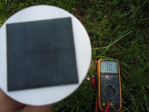
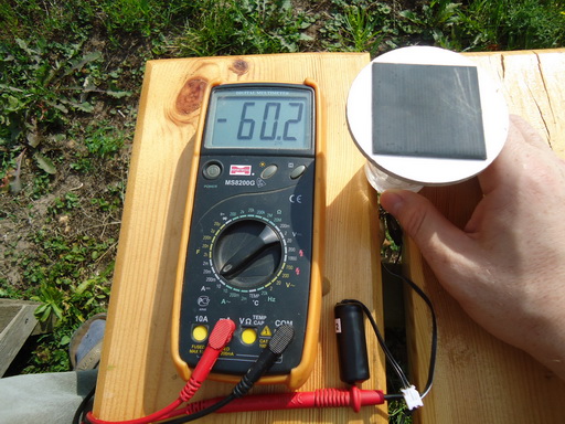
As can be seen from the graphs, the energy of Chinese lanterns accumulated during the day fully corresponds to their consumption currents, the measurement results of which are given below in this article. And if the flashlight is assembled on the basis of solar cells with Aliexpress, then its consumption can be increased by almost an order of magnitude, bringing it to 60 ... 100 mA. It is also worth noting that this schedule is based on the ideal conditions for a solar panel, namely the absence of clouds and shading from trees or buildings. For example, a flashlight charging at an open area with a current of 60 mA:
When shading from a small plum: It
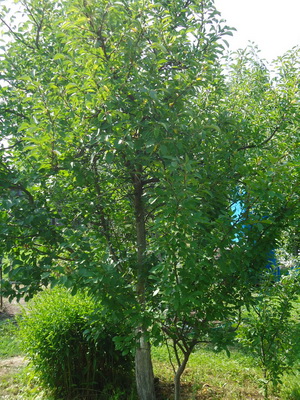
gives out half the charge current, which must be taken into account when placing the flashlights on the ground:
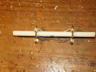
And now about the negative properties of batteries made of polycrystalline silicon wafers. In most cases, these batteries represent the base of the getinax, on which photographic plates are connected by soldering with the help of a tire and filled with a transparent compound based on epoxy glue. The photograph shows two flashlights of the two seasons:

Over time, the surface of the solar battery collapses from solar radiation and when it gets wet it becomes covered in white, which of course does not have a positive effect on the efficiency of the solar battery. The photo below shows the same lanterns after another season:

The situation can be saved by polishing, for example with the help of GOI paste, or in extreme cases you can soak the solar battery in warm water and then clean off the plaque with the help of an old toothbrush, or better with tooth powder. Bottom photo of the same solar lanterns after cleaning.

In the photo, the battery from Aliexpress is 56.8x56.8 mm, spent 2 seasons and spent several hours in water:

The same battery after brushing: With a toothbrush
, practice shows that the performance after such brushing is restored almost completely, below the test of the new battery:
And the battery after brushing :
The difference is only 5 mA, which can be partly attributed to the variation of parameters of solar cells in the party. It is also worth noting that the transparent compound that is used in this type of solar cells is not resistant to alcohol, solvents, and if you wipe the solar battery with them, the compound almost immediately begins to deteriorate and turn white.
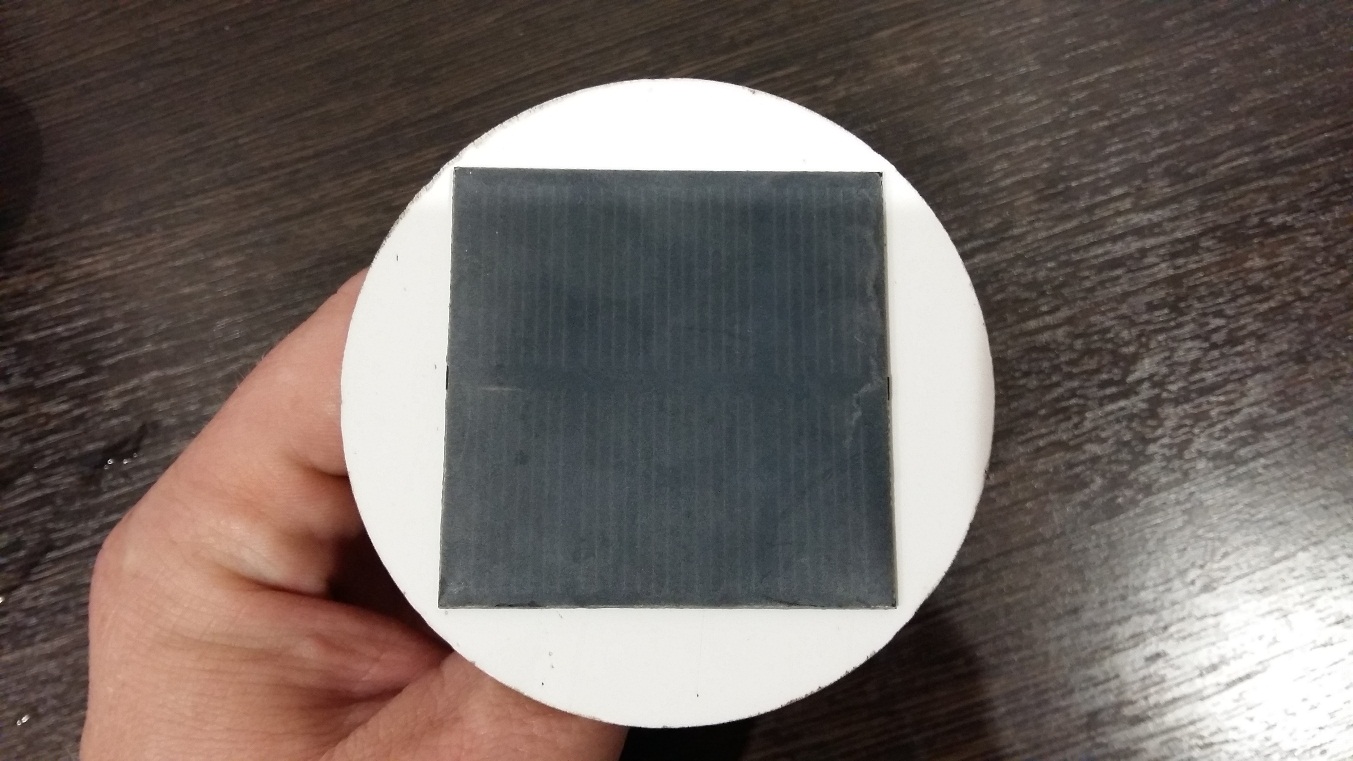
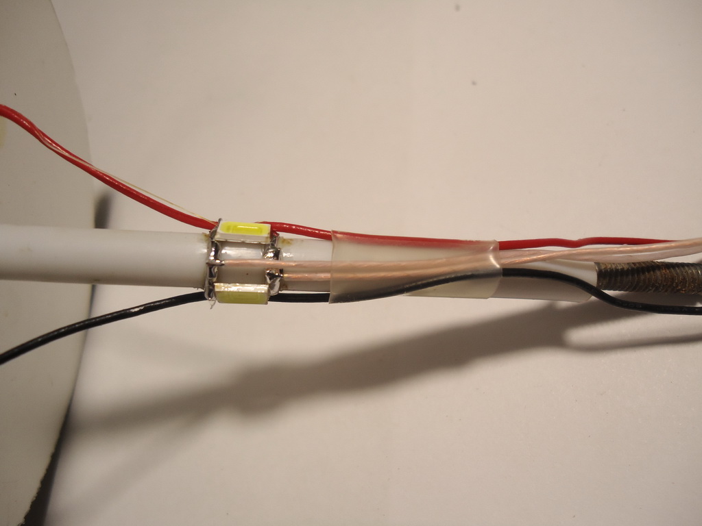
Also there are solar cells made of polycrystalline silicon laminated into polyethylene:

As practice has shown, this is the most practical solution, the battery in the photo has been used for 4 seasons in a self-made solar torch!
Scheme
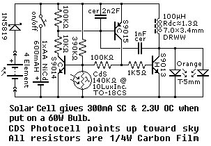
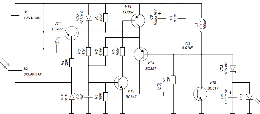
Now let's talk about e-filling solar lanterns. We will not consider circuits on transformers due to the laboriousness of their manufacture. The electronics of the first-generation solar torches were built on discrete elements. Three classic schemes are shown in the figures below, and if you look closely you can see that the node of the actual upconverter in them is almost completely identical and the main differences are only in the method of analyzing the illumination and the power supply of the LEDs. In the first two circuits, additional photoresistors are used to analyze the illumination, and in the third circuit, the solar battery is used as the light sensor, and the LED is connected in parallel with the integrating capacitor, which smooths the voltage spikes, but more on that later.

Scheme 1
Scheme 2
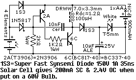
Scheme 3
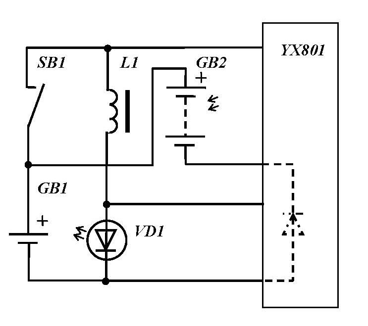
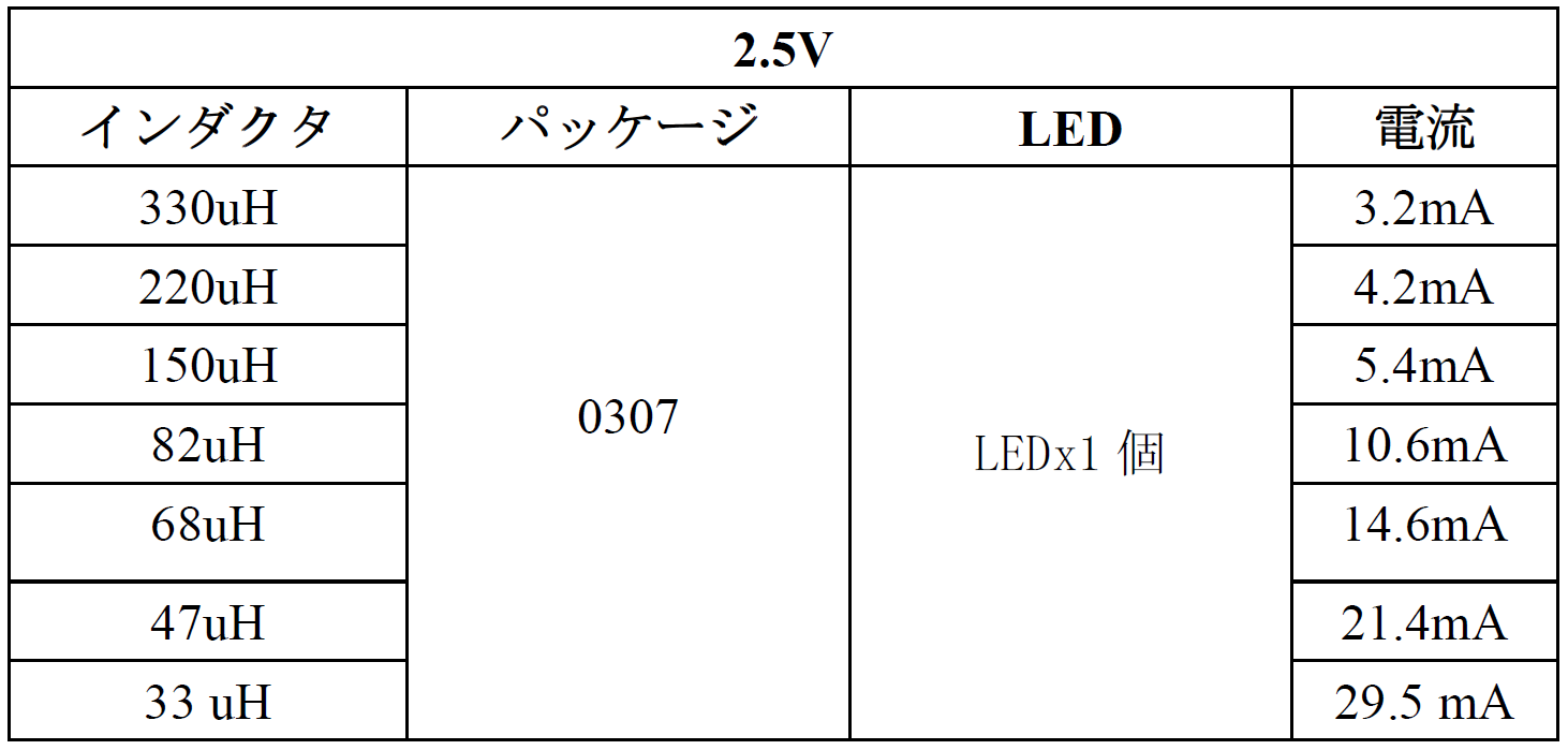
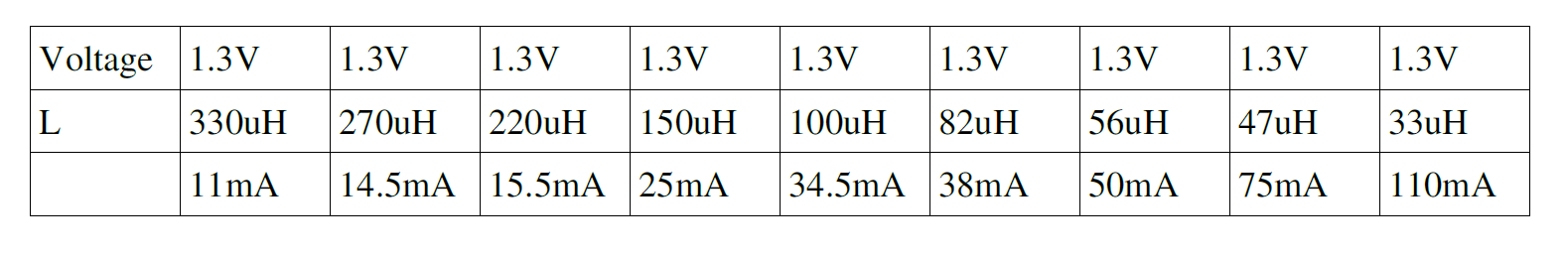
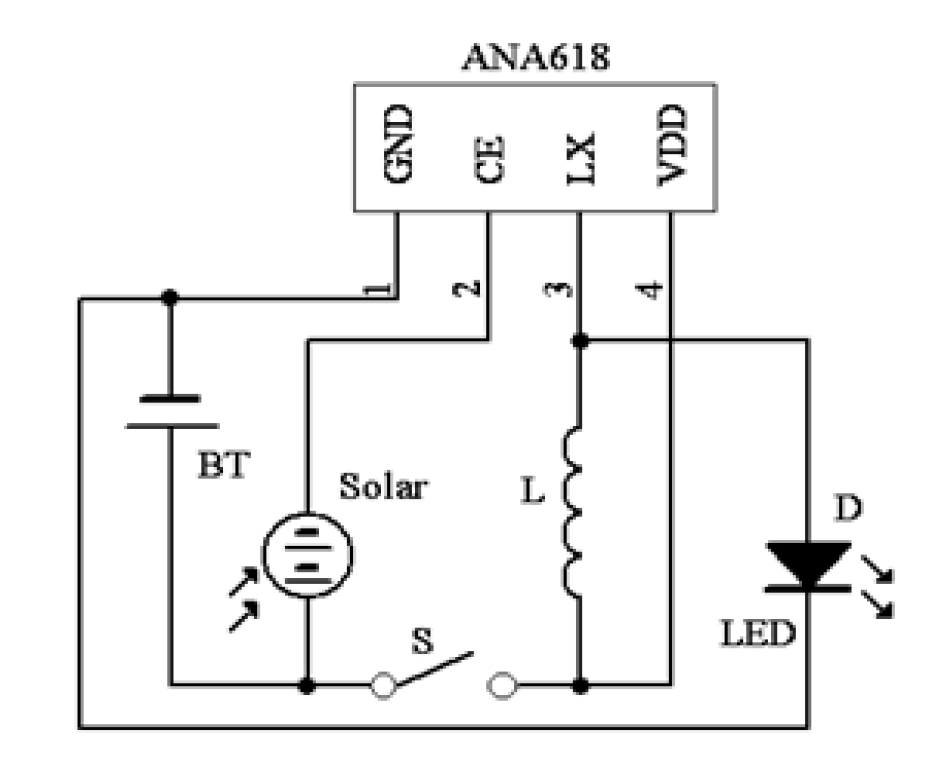
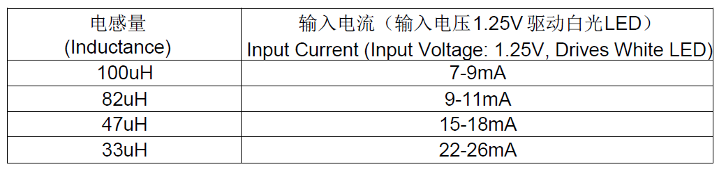
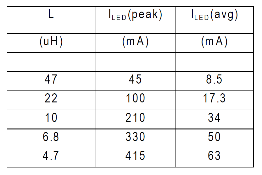
Modern solar lanterns are based mainly on Chinese chips of the YX8XXX, QX5252, ANA618 families. Eminent manufacturers, such as Diodes, also produce similar microcircuits, but due to the fact that their cost is likely much higher than that of Chinese microchips, in flashlights we hardly ever meet them. Basically, the manufacturers of these microcircuits declare the efficiency of the microcircuits to be no worse than 85%, the average current through the LED is set to the value of the choke, but the manufacturers in datasheets standardize it differently - some lead the average current through the LED (circuits 4, 7), other consumed current from the battery (circuits 5, 6).
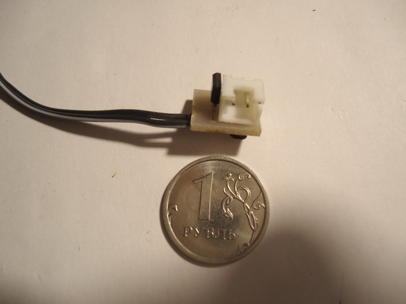
You also need to clarify that in the Chinese lanterns used inductance type - EC-24:

This is an inexpensive low-power choke, with a relatively large internal resistance, which of course reduces the efficiency of the converter.
Scheme 4

Scheme 5
Scheme 6

Scheme 7
Solar lanterns - what's inside?
An autopsy revealed that the flashlight that was purchased in the Globe uses the YX8018 chip:
Inductance of 136 μH nominal:

The flashlight consumption from a source of 1.27 volts is 6 mA:

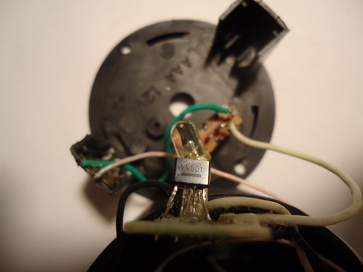
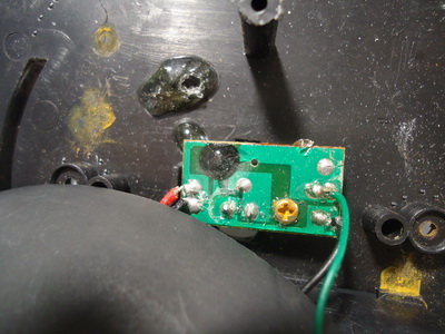
The flashlight from Leroy uses the ANA618 chip: The

inductance of 210 μH nominal : Flashlight
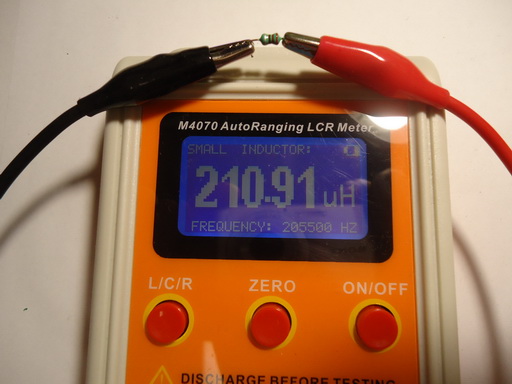
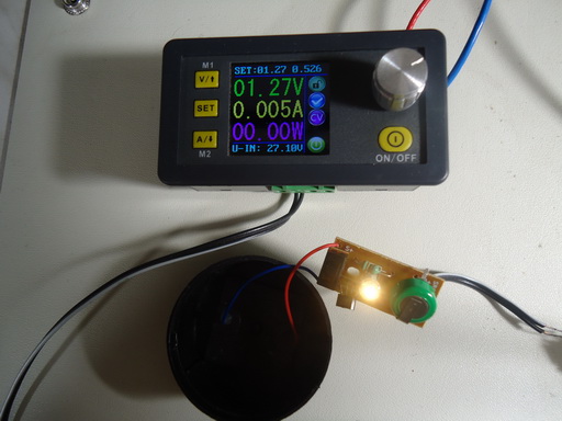
consumption from the source voltage of 1.27 volts is 5 mA:
And in the flashlight from Aliexpress, the famous Chinese chip of the “blot” type is used:
Inductance of 342 μH nominal:
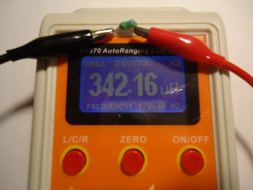
The flashlight consumption from a source of 1.27 volts is 11 mA:

Р The results of this measurement and a quick glance at the table attached to the diagram 5, suggest that we are dealing with a QX5252 microcircuit in a packageless design.
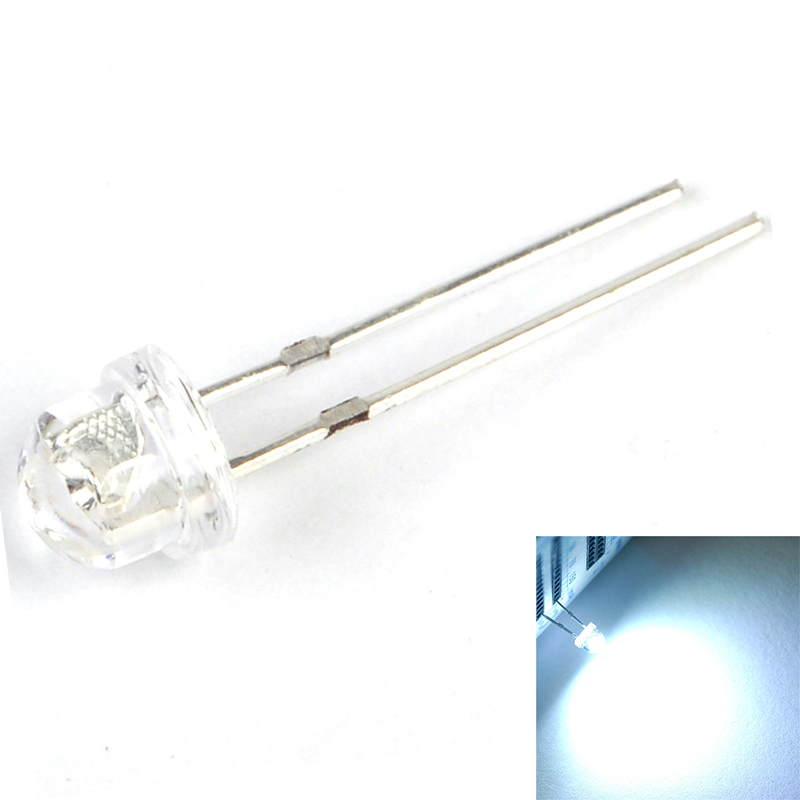
After a successful repetition and adjustment of schemes 1 - 3 schemes, it turned out that, in general, they are efficient, but their characteristics are about the same as those of the Chinese, but they wanted more. Having purchased solar cells for testing, which together with flashlights participated in testing, I first stopped at the current consumption of flashlight circuits of 60 mA, using super-bright LEDs of 5 mm in diameter with a scattering angle of 120 degrees:
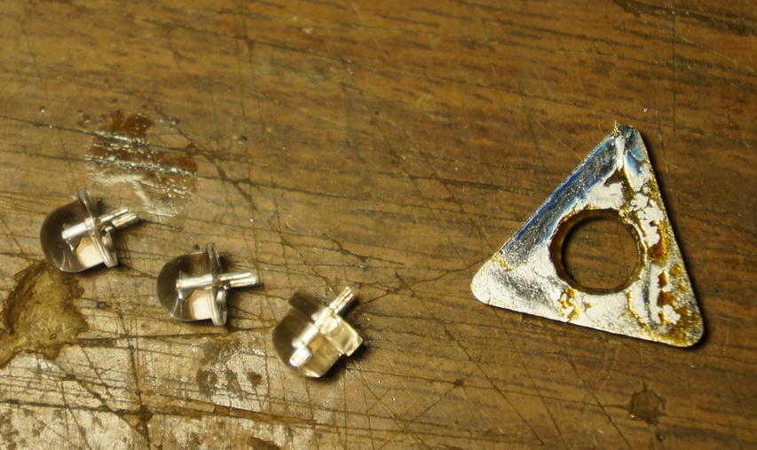
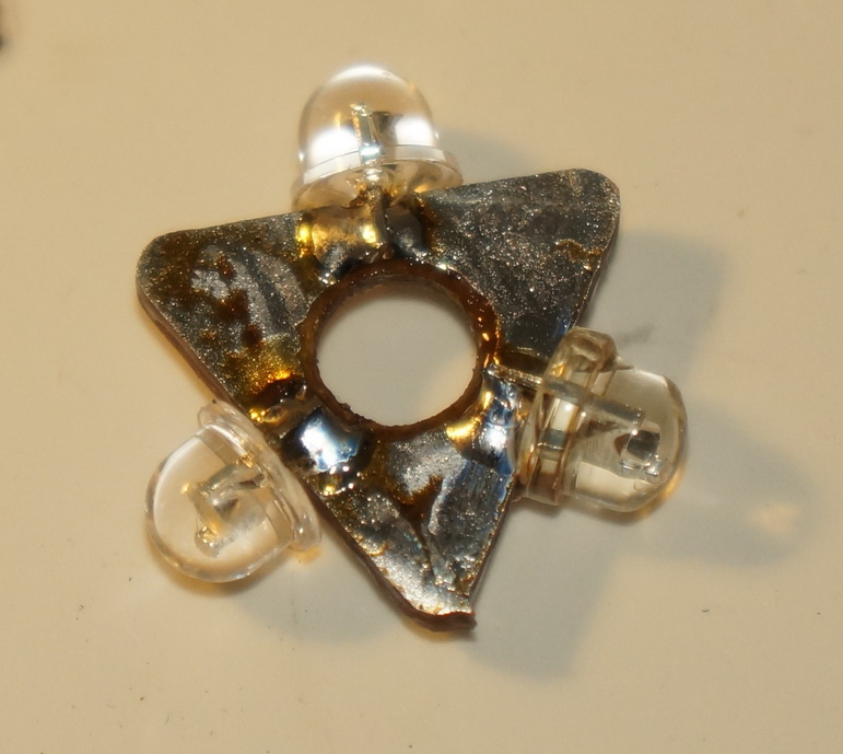
Attempts to make diffusers not successful in Chinese lanterns and I came here to this design by applying it together with scheme 9:
These LEDs have a drawback - the point source of light and therefore the ceiling lamps had to choose matte, transparent ceiling lamps to matte covering with translucent white acrylic varnish or making inserts from white film. But when I chased after brightness and switched to 100-120 mA of flashlight consumption currents, we had to completely reject 5 millimeter LEDs, even a parallel connection of six LEDs did not help:
Low-power LEDs simply could not work effectively on peak currents, so I had to switch to assemblies of three 0.5 watt LEDs of 5730 size and scheme 8:

Looking ahead, I note that with 5730 LEDs, unlike 5 millimeter LEDs, there is no need to matt the ceiling lamps, which again increases the brightness s flashlight.
In Figures 8, 9, the schemes developed by me on the basis of the schemes in Figures 1 - 3. These are “workhorses”, which have shown their reliability and unpretentiousness for 3 seasons. Circuit 8 is designed to work with one 1 - 3 watt LED, or three 0.5 watt 5730 type. Circuit 9 is designed to work with flashlights - garlands based on parallel-connected low-power LEDs of the same type, for example, the same 5 millimeter. The basis of both schemes is a step-up converter with transistors VT4, VT5, inductor L1, feedback capacitor C4, a base current limiter R7 and a bias current resistor R8. This unit is almost completely identical with the first three schemes. But there are differences, it is the amplifier of the light sensor on the transistor VT1, which made it possible to achieve a later turn on of the flashlight in the early twilight compared with the original schemes. As well as the voltage sensor, which performs the function of protecting the battery from deep overdischarge, prohibiting the operation of the boost converter if the battery voltage is below 1.1 volts. The sensor is implemented on a diode VD2 and transistor VT2. If the battery voltage is below 1.1 volts, then the two PN transitions connected in series by the VD2 diode and the emitter junction of the VT2 transistor will be closed, as well as the VT3 transistor, allowing the up-converter to turn on. Resistor R4 sets the hysteresis level of the voltage sensor circuit. Resistors R7, R8 sets the current consumed by the up-converter unit from the battery. With these ratings, the current consumption of the circuit will be 95-120 mA with an average current through the LED of about 20 mA. I measured the current indirectly. A switch device from a tape recorder was connected to the solar battery. Directing the LEDs on the solar battery and finding the position in which the arrow deflected to a maximum and remember its position:

Then we connect the LEDs to an adjustable current source. By adjusting the current through the LEDs, we ensure that the arrow is in the same position as in the previous measurement:
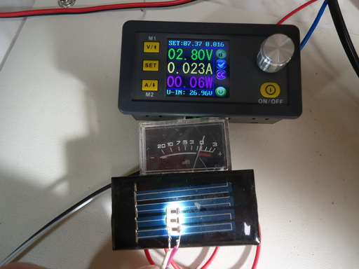
I got 23 mA with a voltage of 2.8 V on the LED. It turns out that the efficiency measured by such an indirect method is equal to only 52%, which is not surprising because The fact that the Uke saturation of the silicon transistor BC817 is 0.6 volts.

Scheme 8
Scheme 9
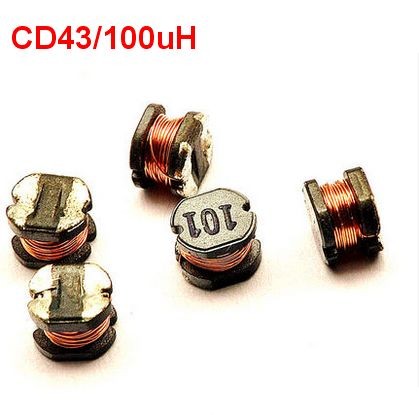
When ordering transistors for this circuit, keep in mind that the Chinese BC817 transistors from Aliexpress can operate incorrectly with a current consumption of 50 - 60 mA and low circuit efficiency. Transistors of ON Semiconductor, or NXP firms work normally. The circuit uses resistors and ceramic capacitors of size 0805, electrolytic tantalum capacitors in the CASE-A package and with a capacity of 10 - 47 μF and an operating voltage of at least 10 volts. The 1SS314 diode can be replaced by the widely used LL4148, 1SS357 diode on SS16 and similar schottky diodes. L1 throttle, frame size CD43 100 μH:
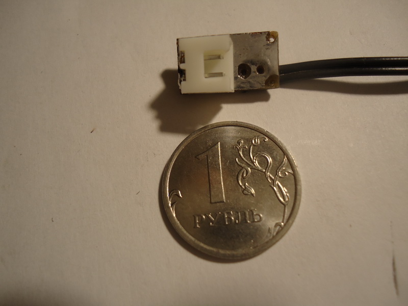
Transistors BC847, BC857 is better to use the index C, they have a maximum gain h21E. The operating voltage of the capacitor C5 in circuit 9 should be at least 16 volts and a capacity of at least 10 microfarads. When trying to reduce it to 1 uF (I wanted to replace a sufficiently large electrolytic capacitor in the case in CASE-A with a smaller ceramic in case 0603), the 5 mm LEDs, due to the non-smoothed emission of voltage pulses from the converter, began to fail permanently, I had to return to the original face value. The boards are manufactured according to the standard LUT technology, the connectors on the board and the battery are used as a switch: The

board is universal for the diagrams in Figures 8, 9. In the photo, the board is assembled according to scheme 8 (capacitor C5 is not installed).
The link to the archive with the circuits and printed circuit boards (in the format of P-CAD 2006 and .pdf) The
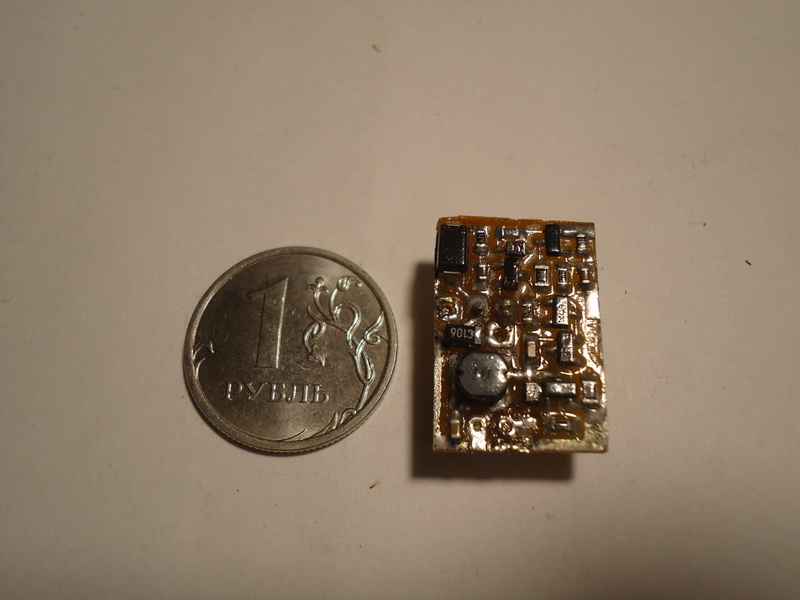
circuit 10 on the exotic and relatively expensive ZXLD383 chip from DIODES showed itself well. Capacitor C1 ceramic 0805, choke L1 size CD43 10 μH. HL1 is an assembly of three 5730 type LEDs. With the indicated ratings, the current consumption of the circuit is 100 - 110 mA.
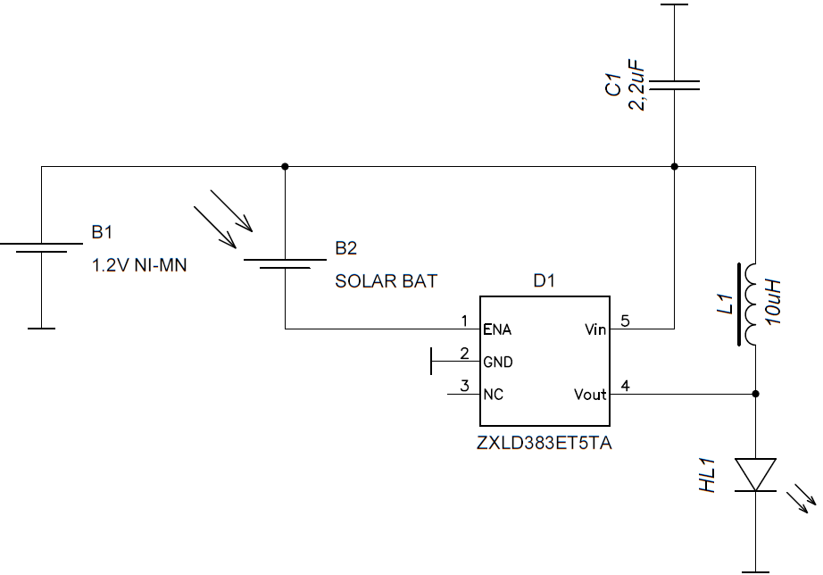
Scheme 10
Assembled, it looks like this:

Link to the archive with diagrams and printed circuit boards (in P-CAD 2006 format and .pdf)
And finally, the most optimal by the criterion of price / quality scheme on the Chinese chip company QX Micro devices QX5252. Capacitor C1 ceramic 0805, choke L1 size CD43 22 μH. HL1 is an assembly of three 5730 type LEDs. With the indicated ratings, the current consumption of the circuit is 100 - 110 mA.

Scheme 11
Assembly:

Link to the archive with diagrams and printed circuit boards (in the format of P-CAD 2006 and .pdf)
For the sake of interest, tests were carried out using a lux meter:
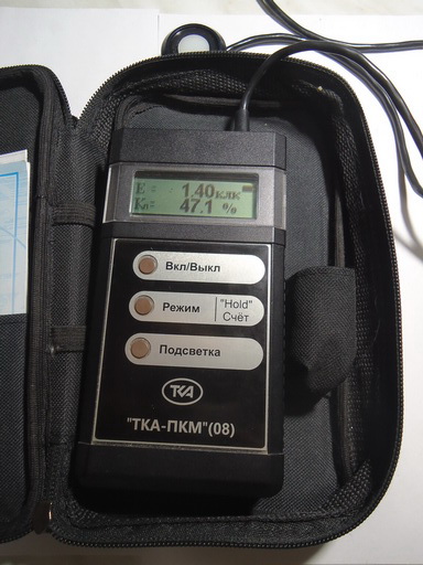
Results in the table:
| Torch | Current consumption, mA | Illumination, CLA |
| Aliexpress | eleven | 0.9 |
| globe | 6 | 2.7 |
| Leroi | five | 7.58 |
| ZXLD383 (Scheme 10) | 112 | 95 |
| QX5252 (Scheme 11) | 109 | 114 |
| Scheme 8 | 93 | 101 |
I will give a few photos.
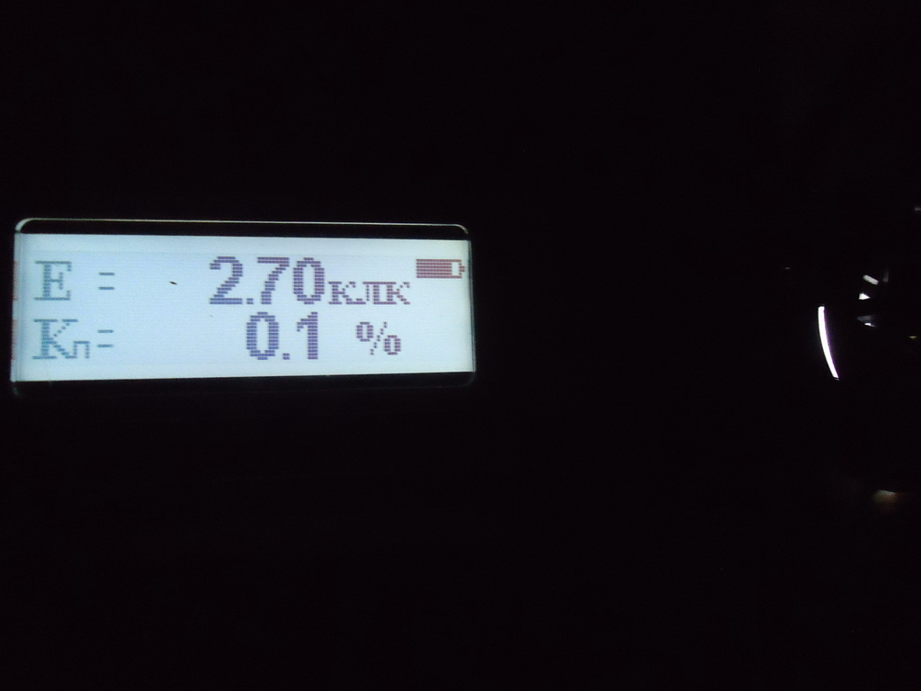
Flashlight test from Globe: QX5252 chip test (Scheme 11):

It seems to me that everyone is already bored with bare numbers and diagrams, so looking ahead I will show you how to see the Globe flashlight from the left (left) and the flashlight based on Scheme 11 in the evening ( right):
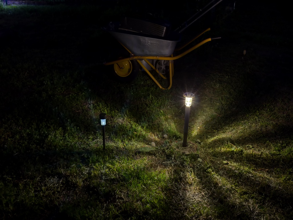
And about the designs of lanterns based on the above schemes, we will talk next time ...