Refinement of Livolo circuit breakers for low-load operation
More about Livolo circuit breakers.
Livolo's touch-sensitive radio-controlled switches are wonderful for everyone (they can directly replace a conventional switch, they do not require a third wire, low own consumption, radio controls, a wide assortment), except for one thing - they work poorly or do not work at all with a small load such as economical LED lamps (less than 15 watts) ) and with devices for smooth ignition of incandescent lamps.
This is directly written in the specification of circuit breakers. Livolo offers an additional block to fix the problem (VL-PJ01).
It would seem that everything is fine, but the additional unit costs money, and when connected in parallel with the lighting device, it obviously eats additional electricity. This reduces the savings from the use of the LED device and reduces the reliability of the system. In fact, the additional capacity creates additional power consumption, although reactive.
I did not hold this additional block in my hands, but I believe that an X2 type capacitor with a capacity of 470 or 680 nanofarads is installed inside it. Why type X2? It is necessary that the system be protected from accidental breakdown of this capacity, and X2 type capacitors are just made to self-repair after a breakdown.
The disadvantage of this solution is the appearance of an additional reactive component in the consumption of the lamp, the presence of an additional element in the high-voltage circuit and the obvious inconvenience of installing an additional element somewhere in the lamp. For example, in my bathroom and toilet there are 8-watt LED lamps and the cartridges are walled into the wall. The only non-destructive solution is to use adapters with contact sockets. As a basis, I used adapters purchased in Leroy for 22 r. Unfortunately, their quality was completely unsatisfactory, the metal of the screw-in part resembled foil and behaved accordingly - when screwed, it was deformed. I used a screw part from the usual still Soviet incandescent lamp. I broke it, cleaned it from glass, and soldered it and glued it together into a single design:

large capacitor:

The solution is quite functional, but has obvious disadvantages, I will list them again:
- the presence of a capacitor in the circuit leads to the appearance of reactive current
- the appearance of the design is strange ...
Therefore, I thought, what exactly prevents the switch from switching small loads?
I examined the circuit shot and posted by mChel (http://we.easyelectronics.ru/Shematech/preparirovanie-sensornogo-vyklyuchatelya-livolo.html).
Let me put a copy of this circuit here:

I put together a test bench and watched the behavior of the circuit breaker with a small load.
The switch with a small load, when trying to turn on the light, clicks and almost immediately releases the relay. If the switch is two-line (that is, it can switch two loads), then when you turn on the standard load first and then small - it will work perfectly fine. If you turn on a large load, then a small one and turn off a large one - a small one will remain working.
Those. Actually, the relay power circuit may well provide the relay with normal power in the on state. This part in the mChel diagram is highlighted in green.
The relay does not have enough power in transition mode - when a command came to turn on the relay, it closed, the circuit breaker circuit should go to power from the green part, but until the load works (the LED lamp turns on with a noticeable delay, IMHO about 400 ms, the lamp fuses Incandescent has a delay of about 2000 ms) - the relay must be powered by the energy stored in the capacitor C6 (330 microfarads per 25 volts). This energy is obviously not enough.
ATTENTION! The circuit breaker has galvanic contact with a network of 220 volts. All work with the circuit breaker can only be done with a complete blackout of the circuit - i.e. both wires must be disconnected from the mains. Failure to follow safety precautions can damage your health.
The first solution is to put a larger capacitor in parallel with this capacitor, I applied 1000 microfarads per 35 volts. The effect is curious - the system does not turn on at all. The blue LED flashes, but only - there is no reaction to the touch of the sensor, the relay does not work. By turning off the power of the test circuit for a short interval, you can sometimes turn on the system and then it works normally. And sometimes the blue LED starts flashing, cyclically repeating a phrase.
I concluded that the microprocessor does not start. Studying the manual on the Microchip 16F690 processor confirmed my assumption - the Power on Reset system normally starts the system at a slew rate of supply voltage not less than that specified in Table 17.1

Thus, we have two boundary values - with a power filter capacity of 330 microfarads, there is little energy, and at 1330 (330 + 1000) microfarads, the rate of increase in the supply voltage is small and the processor does not start.
In a series of successive approximations, I determined that for a switch that commutes an 8-watt LED lamp, an additional capacity of 220 microfarads is enough.
And for switching incandescent lamps with a moderator, it was necessary to put an additional capacity of 680 microfarads.
I was lucky and a solution was found - and there is enough capacity to power the relay while the load goes to operating mode and the rate of increase of the supply voltage is sufficient to start the processor.
If it weren’t lucky, the next idea would be to install the dynistor at a low voltage at the LDO input of the stabilizer U1. I think a 8-10 volt dinistor would be enough. A dinistor is a device that switches on abruptly when the voltage at the terminals rises above a threshold and then remains in the on state until the current through it becomes less than the holding current.
I installed an additional capacitor inside the switch between the boards.

There is enough space there and minimal disassembly is required for revision - you need to remove the glass plate and pull out the top board. Next, we solder an additional capacitor, carefully inspect the installation site, make sure that the soldering is done cleanly, there are no nozzles to adjacent elements, we assemble everything in the reverse order:


After installing the additional capacity after power is supplied for the first time, the switch starts to respond to sensors with a noticeable delay of approximately 40-60 seconds. This does not interfere with normal operation, since it only happens after power is supplied once. Apparently the program in the processor measures the supply voltage and goes to regular operation only after the power supply returns to normal.
I wrapped an additional capacitor with several layers of black electrical tape, the short wires of MGTF were soldered to the terminals, additionally protected by heat shrinkage of the corresponding color (blue minus, red plus). On the Livolo board, the conclusions of the C6 capacitor are located as follows: below the plus, above the minus.

If you put an additional capacitor before mounting in a box, then the scope for placing the tank is much larger.
In a single-line switch, you can place an additional capacitor in place of the missing second relay.
You can replace the capacitor on the board with a larger one (it will be longer) and make a hole in the black plastic case, there is enough space in the usual installation box.
In principle, there is a place between the switch housing and the wiring box.
And in conclusion, I remind you - this circuit has galvanic contact with a 220 volt power supply. Always carry out all changes, assembly, disassembly with complete disconnection from the power supply.
Livolo's touch-sensitive radio-controlled switches are wonderful for everyone (they can directly replace a conventional switch, they do not require a third wire, low own consumption, radio controls, a wide assortment), except for one thing - they work poorly or do not work at all with a small load such as economical LED lamps (less than 15 watts) ) and with devices for smooth ignition of incandescent lamps.
This is directly written in the specification of circuit breakers. Livolo offers an additional block to fix the problem (VL-PJ01).
It would seem that everything is fine, but the additional unit costs money, and when connected in parallel with the lighting device, it obviously eats additional electricity. This reduces the savings from the use of the LED device and reduces the reliability of the system. In fact, the additional capacity creates additional power consumption, although reactive.
I did not hold this additional block in my hands, but I believe that an X2 type capacitor with a capacity of 470 or 680 nanofarads is installed inside it. Why type X2? It is necessary that the system be protected from accidental breakdown of this capacity, and X2 type capacitors are just made to self-repair after a breakdown.
The disadvantage of this solution is the appearance of an additional reactive component in the consumption of the lamp, the presence of an additional element in the high-voltage circuit and the obvious inconvenience of installing an additional element somewhere in the lamp. For example, in my bathroom and toilet there are 8-watt LED lamps and the cartridges are walled into the wall. The only non-destructive solution is to use adapters with contact sockets. As a basis, I used adapters purchased in Leroy for 22 r. Unfortunately, their quality was completely unsatisfactory, the metal of the screw-in part resembled foil and behaved accordingly - when screwed, it was deformed. I used a screw part from the usual still Soviet incandescent lamp. I broke it, cleaned it from glass, and soldered it and glued it together into a single design:
large capacitor:
The solution is quite functional, but has obvious disadvantages, I will list them again:
- the presence of a capacitor in the circuit leads to the appearance of reactive current
- the appearance of the design is strange ...
Therefore, I thought, what exactly prevents the switch from switching small loads?
I examined the circuit shot and posted by mChel (http://we.easyelectronics.ru/Shematech/preparirovanie-sensornogo-vyklyuchatelya-livolo.html).
Let me put a copy of this circuit here:
I put together a test bench and watched the behavior of the circuit breaker with a small load.
The switch with a small load, when trying to turn on the light, clicks and almost immediately releases the relay. If the switch is two-line (that is, it can switch two loads), then when you turn on the standard load first and then small - it will work perfectly fine. If you turn on a large load, then a small one and turn off a large one - a small one will remain working.
Those. Actually, the relay power circuit may well provide the relay with normal power in the on state. This part in the mChel diagram is highlighted in green.
The relay does not have enough power in transition mode - when a command came to turn on the relay, it closed, the circuit breaker circuit should go to power from the green part, but until the load works (the LED lamp turns on with a noticeable delay, IMHO about 400 ms, the lamp fuses Incandescent has a delay of about 2000 ms) - the relay must be powered by the energy stored in the capacitor C6 (330 microfarads per 25 volts). This energy is obviously not enough.
ATTENTION! The circuit breaker has galvanic contact with a network of 220 volts. All work with the circuit breaker can only be done with a complete blackout of the circuit - i.e. both wires must be disconnected from the mains. Failure to follow safety precautions can damage your health.
The first solution is to put a larger capacitor in parallel with this capacitor, I applied 1000 microfarads per 35 volts. The effect is curious - the system does not turn on at all. The blue LED flashes, but only - there is no reaction to the touch of the sensor, the relay does not work. By turning off the power of the test circuit for a short interval, you can sometimes turn on the system and then it works normally. And sometimes the blue LED starts flashing, cyclically repeating a phrase.
I concluded that the microprocessor does not start. Studying the manual on the Microchip 16F690 processor confirmed my assumption - the Power on Reset system normally starts the system at a slew rate of supply voltage not less than that specified in Table 17.1
Thus, we have two boundary values - with a power filter capacity of 330 microfarads, there is little energy, and at 1330 (330 + 1000) microfarads, the rate of increase in the supply voltage is small and the processor does not start.
In a series of successive approximations, I determined that for a switch that commutes an 8-watt LED lamp, an additional capacity of 220 microfarads is enough.
And for switching incandescent lamps with a moderator, it was necessary to put an additional capacity of 680 microfarads.
I was lucky and a solution was found - and there is enough capacity to power the relay while the load goes to operating mode and the rate of increase of the supply voltage is sufficient to start the processor.
If it weren’t lucky, the next idea would be to install the dynistor at a low voltage at the LDO input of the stabilizer U1. I think a 8-10 volt dinistor would be enough. A dinistor is a device that switches on abruptly when the voltage at the terminals rises above a threshold and then remains in the on state until the current through it becomes less than the holding current.
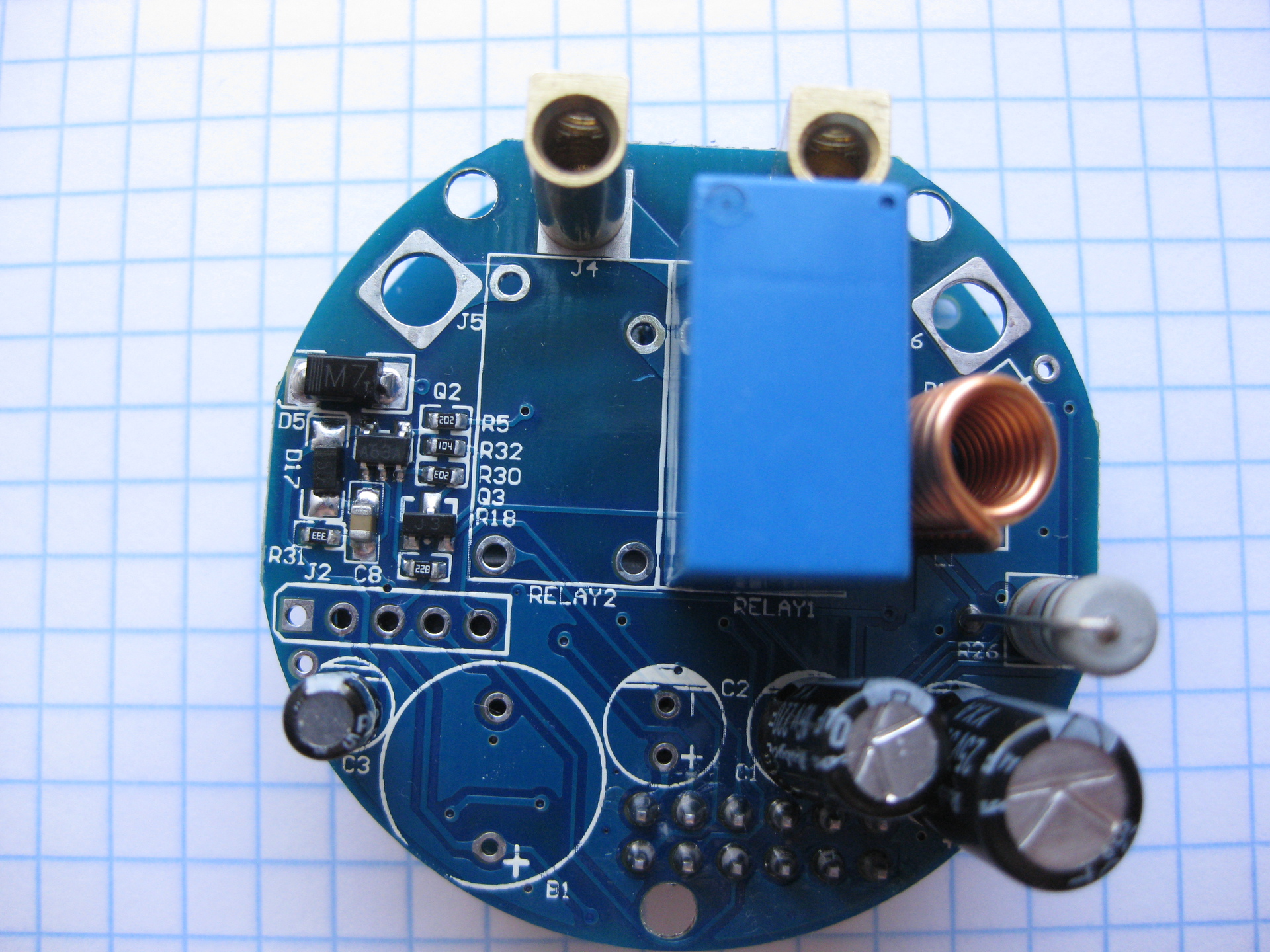
I installed an additional capacitor inside the switch between the boards.
There is enough space there and minimal disassembly is required for revision - you need to remove the glass plate and pull out the top board. Next, we solder an additional capacitor, carefully inspect the installation site, make sure that the soldering is done cleanly, there are no nozzles to adjacent elements, we assemble everything in the reverse order:
After installing the additional capacity after power is supplied for the first time, the switch starts to respond to sensors with a noticeable delay of approximately 40-60 seconds. This does not interfere with normal operation, since it only happens after power is supplied once. Apparently the program in the processor measures the supply voltage and goes to regular operation only after the power supply returns to normal.
I wrapped an additional capacitor with several layers of black electrical tape, the short wires of MGTF were soldered to the terminals, additionally protected by heat shrinkage of the corresponding color (blue minus, red plus). On the Livolo board, the conclusions of the C6 capacitor are located as follows: below the plus, above the minus.
If you put an additional capacitor before mounting in a box, then the scope for placing the tank is much larger.
In a single-line switch, you can place an additional capacitor in place of the missing second relay.
You can replace the capacitor on the board with a larger one (it will be longer) and make a hole in the black plastic case, there is enough space in the usual installation box.
In principle, there is a place between the switch housing and the wiring box.
And in conclusion, I remind you - this circuit has galvanic contact with a 220 volt power supply. Always carry out all changes, assembly, disassembly with complete disconnection from the power supply.