Environmental monitoring in the server room (Bolid + Zabbix)
- Tutorial
Probably the easiest way for an IT professional to solve the problem of monitoring the environment in a server room would be to use specialized controllers with issuing data via SNMP (for example, NetBotz or NetPing). But for those who are not afraid of difficulties and want to get an inexpensive solution at the industrial level (with the serial production of equipment) - there is an interesting option with the Modbus protocol.

Below I will describe the monitoring system based on Russian-made components - BVD, and we will “merge” the data in Zabbix 4.0. NVP "Bolid" is widely known in the circles of fire and security automatics and the decision in question will carry this "imprint". Their devices, to put it mildly, do not differ in the design and thoughtfulness of the cases, but ... the price more than compensates for all these shortcomings. It is worth noting very good documentation and more or less normal free technical support.
Before moving on to hardware, we’ll take a very brief look at the protocols and interfaces used:
Modbus : an industrial protocol built according to the Master (Slave) principle. In the Modbus network, there can be only one master who interrogates the slaves and “tells” what to do. It can use RS-485 (Modbus RTU) or Ethernet (Modbus TCP) interface as a transmission medium. Theoretically, the maximum number of devices - 247.
Orion : a proprietary protocol of the company NVP "Bolid", built on the principle of "Master" (Master) - "Slave" (Slave). Apparently, the modified RS-485 interface is used as the data transmission medium, due to which the maximum line length can reach 3 km (!). The maximum number of devices - 127.
DPLS(two-wire communication line): the proprietary protocol of the company NVP "Bolid", built on the principle of "Master" (Master) - "Slave" (Slave). Copper pair cable is used as data transmission medium (“twisted pair” is recommended). The maximum number of devices - 127 + 1. The topology is a bus (or ring) with branches, the maximum length of the line can reach 1.5 km (depends on the type of cable, the cross section of the cables and the number of connected devices).
RS-485 : physical layer interface, uses “twisted pair” for data transfer (one “2-wire” or two pairs “4-wire”, the second is less common). The stated maximum line length is 1.2 km. Topology - tire.
As you can see, rather long-distance communication lines are used. In all protocols, device addressing is set by "handles" (pre-configuration).
The system assumes the connection of “special” (proprietary) address sensors (more strictly speaking, “detectors”, i.e. devices with a built-in sensor), but you can also connect “regular” untargeted ones using address expanders (from 1 to 8 inputs). The use of addressable detectors offers two advantages: almost all addressable devices are powered via a signal line (i.e., there is no need to connect a separate 12V power line) and there is no need to place an address expander anywhere. Sensors are connected to the DPLS .
The range of "terminal" equipment is quite wide, but I will give what may be required when solving our problem:
A complete list of equipment, see the official website of the manufacturer .
The "line" of controllers, so to speak, consists of three models:
It is best to use the S2000-KDL-Modbus, but you can also use the S2000-KDL / C2000-KDL-2I with the S2000-PP protocol converter installed next to it, which has a “panel mounting” design.
The controller performs the role of "Master" in the DPLS line (only one DPLS line can be connected to one controller), and in the Orion RS-485 line it already acts as the "Slave" and cannot take data from it "directly". For data acquisition in the RS-485 Orion lines, the so-called S2000M or S2000-PP console (including in the built version) is used, which already have standardized data transmission interfaces.
In the above controllers can also highlight the following characteristics:
For system resiliency, you can use the following measures (which are optional):
IMPORTANT: new firmware is constantly being released on the controllers, which eliminate errors and add functionality, and firmware S2000-KDL and S2000-KDL-2I are incompatible.
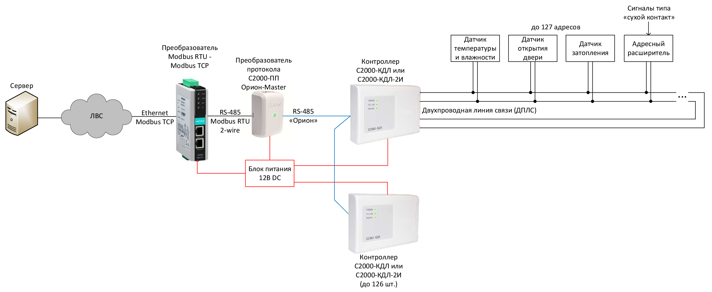
As described earlier, you can use either the S2000-Modbus controller or the S2000-PP converter. Both schemes provide for the issuance of signals via the Modbus RTU 2-wire protocol using RS-485 as a slave device (our master is Zabbix or some SCADA system). To connect to the server, you can use two methods:
There are two possible schemes for sending events to the Modbus protocol:
The power supply requires a 12V DC power supply, preferably stabilized and mounted on a DIN rail. Its power (usually indicated either in mA or A) can be roughly matched at the rate of 1 controller - 500 mA. I would recommend using a redundant power source (with built-in battery, RIP) only when using the S2000M remote control. And be sure to connect the power supply to the same uninterruptible power supply (UPS) as the monitoring system server.
You can of course mount all this on the wall, but we leave it for the installers of security and fire alarms, and use the 3U DIN-rail for mounting in a 19 "cabinet (for example, TsMO PS-3U or Cabeus with the same part number, the front panel will have to be thrown out In the case of using the S2000-M remote control, you can use a 19 "4U plug (preferably perforated), which will serve as a mounting plate and to which you will already fix the DIN rail for the terminals and the controller. The minus of the solution is that the equipment stands for the 19 "installation plane.
Assembling and mounting a system from components should not cause any problems, but pay attention to the following:
For those who do not want to solder, but likes to crimp the "chips", you can use the option described below (probably, it’s better to use RJ11, so as not to accidentally switch the DPLS line to the server).
It will take:
On one pair we start DPLS, on the other, for example, 12V DC. Connecting sensors through splitters.
For the "practical" part a stand was assembled consisting of:
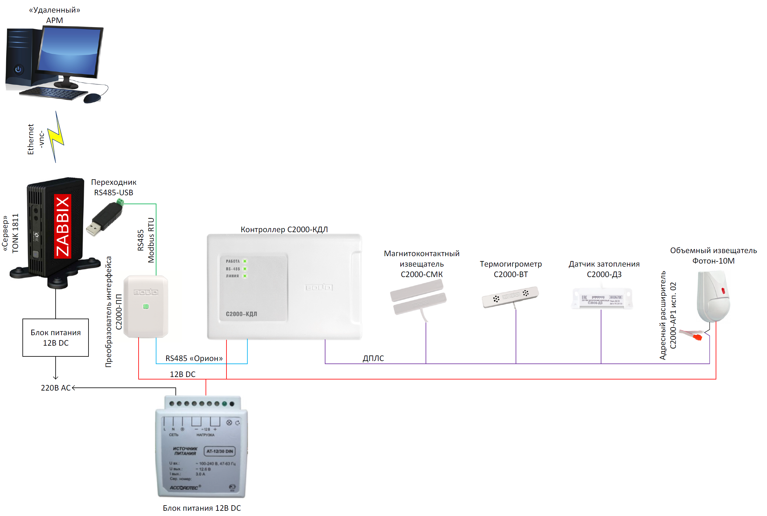
All settings are made in the Windows environment, respectively, before starting work, you need to install the driver on the RS-485 / USB adapter, as well as two “super” programs from BHP, which are supplied for free: Orion-prog and Uprog . Next, the devices are separately connected to the RS-485 / USB adapter to the AB RS-485 “Orion” ports (direct layout is used, and not like on COM ports).
IMPORTANT: for all subsequent steps at S2000-PP jumper XP1 on the board should be removed.
Step 1. Insert the RS-485 / USB adapter into the USB connector and see in the device manager which COM port number is assigned to the adapter. Drivers for the adapter must be installed without exclamation marks in the "Device Manager".
Step 2. On behalf of the administrator, launch Orion-prog, select the required COM port and search for and view the firmware version of the device. Go to the manufacturer's official website and check for a more recent firmware and, if necessary (most likely required) - perform an update (at the time of writing this article: for S2000-PP - 1.32, S2000-KDL - 2.22).
* In fact, firmware 1.32 was set “crookedly” - the Uprog configuration was not read from the device. Therefore, "rolled back" back to 1.31.
Step 3. Setting the address at the instruments (first with S2000-PP, for example, 2 and then with S2000-KDL - 3). To do this, run the Uprog - all devices have the default address 127, so you need to configure the devices at the beginning one by one. For more detailed videos from the manufacturer, see YouTube .
Step 4. After setting the address on the S2000-KDL, it is necessary to set the addresses of the sensors in the two-wire communication line (DPLS). They also have the default address 127 (and the circle with the sensor in the Uprog is not highlighted). We read the configuration of the device (Ctrl + F3) and in series connect sensors to the DPLS outputs, setting addresses. When pointing to the sensor in the context menu “Request AU Type”, you can specify the type of sensor or “Request A / D ADC” - find out if the sensor works (for example, for a magnetic-contact detector ADC when closing: 100, and when opening: 50). In fact, I have the following address configuration: 1 - reed switch S2000-SMK, 2 - temperature C2000-BT, 3 - humidity C2000-BT, 4 - leakage C2000-DZ, 5 - address extender S2000-AP1 isp. 02 (with the Foton-10M volume detector connected to it).
Next, go to the "Inputs" tab and do the following:
After all the “manipulations” with the S2000-KDL, we perform the “Configuration recording in the device”.
Step 5. Configure S2000-PP.
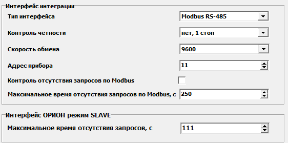
On the tab "Device" settings are shown in the picture (this is the most "running" and on most devices they go by default). Similar settings should be at the COM-port of the RS-485 / USB adapter and any other device connected to the Modbus network. For the S2000-PP device in the Modbus network, I chose address 11 (the address in the Orion system is 2!).
Then go to the tab "Devices" and begin to fill in the "Zone Table":

After setting up the S2000-PP, we perform the “Record of the configuration in the device”.
Step 6. We connect S2000-PP and S2000-KDL to the network via RS-485 Orion, connect the sensors to the S2000-KDL (can be a bunch of two terminals), and connect the RS-485 / USB adapter to the Modbus C2000-PP output. The XP1 jumper is installed in the closed position (important: after installing the jumper, the device must be reset by resetting the supply voltage). All - the system is "ready for battle."
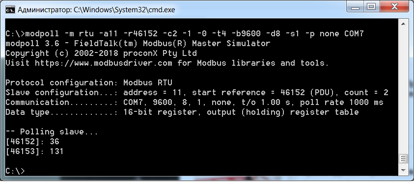
We check the "operability" in the free console program Modpoll Modbus Master Simulator (hereinafter - "Modpoll"), for example, at the address of the firmware "S2000-PP" or by returning information from the C2000-KDL to the address "40000" - this is the first sensor:
Firmware "For review" can be downloaded here .
Warning: Zabbix configured for the first time, like Linux Mint (since Zabbix is not available for Windows) :)
After installing Zabbix, you need to install the autoconf , automake , libtool , pkg-config packages and then the extension module - libzbxmodbus . About him on Habré there is a separate article (I will constantly refer to it) and it has recently been updated, just to work with Zabbix 4.0. The article also has more detailed information on the Modbus protocol. The module itself and more or less detailed instructions are on GitHub .
Small differences in installation from that specified on GitHub:
Studying the work of the libzbxmodbus module, it became clear that using the S2000M remote control circuit would not work, because in this case, receiving data from the thermohygrometers looks like this: writing the number of the required zone to the register 46179 and then taking the data from the register 46328 - that is, very nontrivial (in “large” SCADA systems, this is possible, for example, in MasterSCADA).
Register in the configuration file etc / zabbix / zabbix_server.conf links to the extension and connect the "hardware" to the "server" with Zabbix. I didn’t have to install drivers for the RS-485 / USB adapter, but I didn’t understand how to understand which USB number would be used, it’s good that the connection to / dev / ttyUSB0 worked (you can see if the device is detected in the system)lsusb ).
As with Windows, we check with the help of the Modpoll utility (I ran linux i386) that the hardware was connected and the information was available:

Since the article describes the configuration process using the example of Zabbix 2.2 - there’s a slightly different interface, I’ll provide explanations and pictures settings.
It is a little about in what type the data is provided at interrogation of zones.
Suppose we got the answer in decimal format 9148 (D). Let us translate into hexadecimal format (HEX): we get 23BC - according to the instructions for the S2000-PP device, these are two events with codes 23 (HEX) / 35 (D) and BC (HEX) / 188 (D). Next, we go look at Table 5. "List of events (states of the loop) of the Orion system". In it we find, 35 "Restoration of a technological input" and 188 "Restoration of communication with an entrance". There is no need to translate D-HEX-D, the first event is the integer part of dividing the obtained value by 256, and the remainder is the second event ( 9148 = 35 * 256 + 188). When polling technological inputs, we will take away only the first event (priority), which “must” take states 35 and 36 (“Restoration of the technological input” and “Violation of the technological input”). We will discard the fractional part (the second event) using the setting of the Data Element “Information Type: Numeric (positive integer)”.
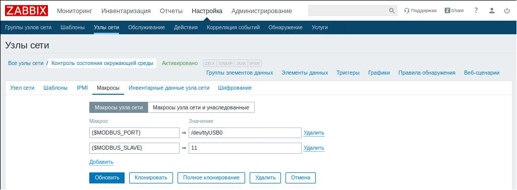
Step 3. Fill in port macros and device numbers:
Setup> Network Nodes> “Environmental Monitoring”> select “Macros”
Step 4. Displaying readings to the control panel:
Start screen> All panels, select "Create panel"> in the appeared window set "Panel name" and the user to whom this panel will be available> Click "Create new widget"> Type "Data view", Update interval "10 seconds", Groups nodes Engineering Infrastructure> Add> Adjust Panel Size and click “Save Changes”:

The resulting system, through the use of "long-range" protocols, can be an excellent solution, both for monitoring the server and a pair of cross, office zones (in terms of monitoring the provision of a temperate-humidity regime) or even a small data center. Someone may say “fu-fu-fu, the car is still that nasty thing, you need to use XXX (to substitute something from the industrial automation)” is also an option, but in my opinion it will be much redundant and also more expensive . And a small nuance: as you can see, the system on the car is quite simple (although there is some strange logic), but to “finish” the decision on the prom. controllers - sometimes he is still a “headache”.
PS This article is an adaptation of two articles on my blog:
Inexpensive monitoring for the server room (part 1 - introductory)
Inexpensive monitoring for the server room (part 2 - practical)
UPD. Adapter RS485-USB after working for 3 days - fell off. It is recognized as unstable, but suitable for commissioning. It was replaced with a single-port MGX MB3170 converter manufactured by MOXA (taken from what was on hand) - everything became stable.
You need to understand that this article is just an example of how to make friends with Zabbix and Bolid. For a real implementation, you can add more monitored DPLS states, as well as, for example, negative temperatures (they are processed a little differently).

Below I will describe the monitoring system based on Russian-made components - BVD, and we will “merge” the data in Zabbix 4.0. NVP "Bolid" is widely known in the circles of fire and security automatics and the decision in question will carry this "imprint". Their devices, to put it mildly, do not differ in the design and thoughtfulness of the cases, but ... the price more than compensates for all these shortcomings. It is worth noting very good documentation and more or less normal free technical support.
Protocols and interfaces
Before moving on to hardware, we’ll take a very brief look at the protocols and interfaces used:
Modbus : an industrial protocol built according to the Master (Slave) principle. In the Modbus network, there can be only one master who interrogates the slaves and “tells” what to do. It can use RS-485 (Modbus RTU) or Ethernet (Modbus TCP) interface as a transmission medium. Theoretically, the maximum number of devices - 247.
Orion : a proprietary protocol of the company NVP "Bolid", built on the principle of "Master" (Master) - "Slave" (Slave). Apparently, the modified RS-485 interface is used as the data transmission medium, due to which the maximum line length can reach 3 km (!). The maximum number of devices - 127.
DPLS(two-wire communication line): the proprietary protocol of the company NVP "Bolid", built on the principle of "Master" (Master) - "Slave" (Slave). Copper pair cable is used as data transmission medium (“twisted pair” is recommended). The maximum number of devices - 127 + 1. The topology is a bus (or ring) with branches, the maximum length of the line can reach 1.5 km (depends on the type of cable, the cross section of the cables and the number of connected devices).
RS-485 : physical layer interface, uses “twisted pair” for data transfer (one “2-wire” or two pairs “4-wire”, the second is less common). The stated maximum line length is 1.2 km. Topology - tire.
As you can see, rather long-distance communication lines are used. In all protocols, device addressing is set by "handles" (pre-configuration).
Sensors
The system assumes the connection of “special” (proprietary) address sensors (more strictly speaking, “detectors”, i.e. devices with a built-in sensor), but you can also connect “regular” untargeted ones using address expanders (from 1 to 8 inputs). The use of addressable detectors offers two advantages: almost all addressable devices are powered via a signal line (i.e., there is no need to connect a separate 12V power line) and there is no need to place an address expander anywhere. Sensors are connected to the DPLS .
The range of "terminal" equipment is quite wide, but I will give what may be required when solving our problem:
- S2000-W - combined temperature and humidity sensor for indoor use (IP41). It has a certificate of measurement, the error is only 0.5 ° C and the recommended retail price is only 1200 rubles!
- S2000-SMK (and its variations) - “door opening” sensor (magnetic contact detector, reed switch). Recommended retail price - 300 rubles.;
- S2000-DZ - point of flooding sensor (done in conjunction with Rielta, so the body is "unformat"). Recommended retail price - 800 rubles.;
- S2000-AP1, S2000-AP2, S2000-AP8 - address expanders for 1, 2 and 8 connections, can be used as "receivers" of signals of the "dry contact" type (on / off) from other equipment (for example, from a fire extinguishing device) or pump conditioner);
- S2000-SP2 is a relay unit (for 2 outputs) with which you can control devices (for example, an alarm lamp with a light indicator). Recommended retail price - 1200 rubles.
Appearance of sensors

A complete list of equipment, see the official website of the manufacturer .
Controller
The "line" of controllers, so to speak, consists of three models:
- S2000-KDL - the basic model (the designation stands for “System 2000 - Two-Wire Communication Line Controller”);
- S2000-KDL-2I - galvanic isolations for RS-485 and DPLS are added;
- S2000-KDL-Modbus - a converter of the Modbus S2000-PP protocol has been added to the S2000-KDL-2I design.
Appearance of controllers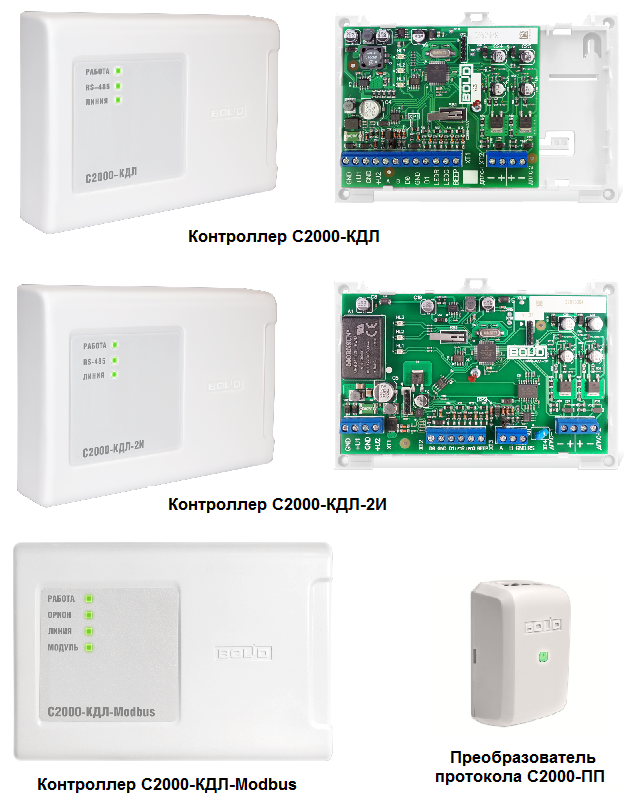

It is best to use the S2000-KDL-Modbus, but you can also use the S2000-KDL / C2000-KDL-2I with the S2000-PP protocol converter installed next to it, which has a “panel mounting” design.
The controller performs the role of "Master" in the DPLS line (only one DPLS line can be connected to one controller), and in the Orion RS-485 line it already acts as the "Slave" and cannot take data from it "directly". For data acquisition in the RS-485 Orion lines, the so-called S2000M or S2000-PP console (including in the built version) is used, which already have standardized data transmission interfaces.
In the above controllers can also highlight the following characteristics:
- refer to a configurable type, not a programmable one (i.e., it is only necessary to adjust the parameters, not to develop a program);
- DPLS support up to 127 addressable devices (S2000-VT has two addresses), and many start-up engineers do not recommend using more than 100-110;
- Dual power input DC 12-24V;
- The housing structure is not very convenient (all the connecting wires cannot be hidden in the instrument housing and you have to remove them from the back of the instrument).
For system resiliency, you can use the following measures (which are optional):
- ring loop - break of the loop in one place does not affect the presence of signals from the address sensors;
- the use of branching-isolating blocks (BREEZE) - allows you to make radial branches, as well as isolate the segment of the loop in which the closure of "DPLS +" and "DPLS-" occurred.
IMPORTANT: new firmware is constantly being released on the controllers, which eliminate errors and add functionality, and firmware S2000-KDL and S2000-KDL-2I are incompatible.
Modbus connection
As described earlier, you can use either the S2000-Modbus controller or the S2000-PP converter. Both schemes provide for the issuance of signals via the Modbus RTU 2-wire protocol using RS-485 as a slave device (our master is Zabbix or some SCADA system). To connect to the server, you can use two methods:
- preferred - Modbus RTU / Modbus TCP converter with connection to the same local network where our software server is located;
- Cheap - RS-485 / USB converter with connection directly to the server. I note that there are many complaints about the reliability of USB stick data (you can take almost any, I ordered from China for 100 rubles, I used RS-232 / RS-485 converter and USB / RS-232 adapter and everything continued to work!).
There are two possible schemes for sending events to the Modbus protocol:
- directly from S2000-PP / C2000-KDL-Modbus, when these devices operate in the Orion-Master mode (selected by a jumper on the board) and act as an interrogator of the Orion system;
- using the S2000M console when it collects information from the controllers and only then sends it to Modbus via the S2000-PP / C2000-KDL-Modbus (Orion-Slave mode). This scheme is good because the console can be used as a “local terminal” (see the events on the built-in LCD screen), and also continue to record events in case of a server failure with the monitoring software. Minus: a little more difficult to set up and the remote has a very specific appearance.
Examples of system diagrams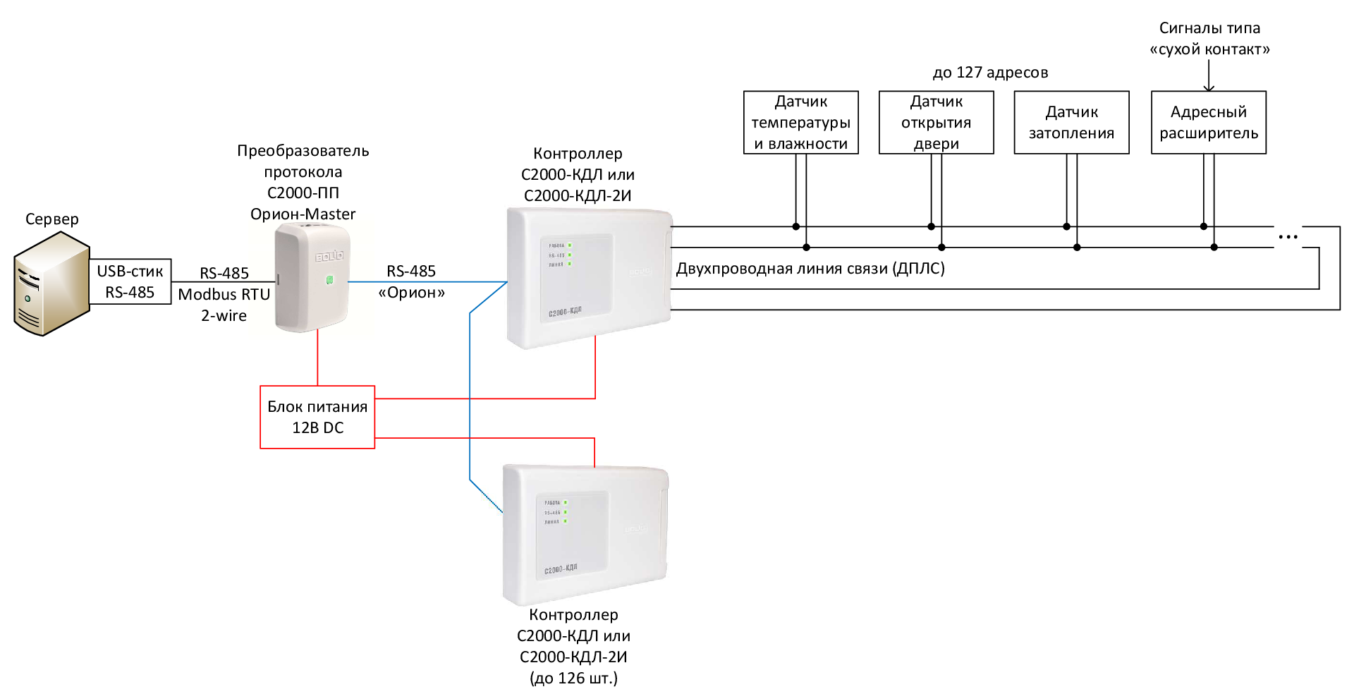


Power and installation
The power supply requires a 12V DC power supply, preferably stabilized and mounted on a DIN rail. Its power (usually indicated either in mA or A) can be roughly matched at the rate of 1 controller - 500 mA. I would recommend using a redundant power source (with built-in battery, RIP) only when using the S2000M remote control. And be sure to connect the power supply to the same uninterruptible power supply (UPS) as the monitoring system server.
You can of course mount all this on the wall, but we leave it for the installers of security and fire alarms, and use the 3U DIN-rail for mounting in a 19 "cabinet (for example, TsMO PS-3U or Cabeus with the same part number, the front panel will have to be thrown out In the case of using the S2000-M remote control, you can use a 19 "4U plug (preferably perforated), which will serve as a mounting plate and to which you will already fix the DIN rail for the terminals and the controller. The minus of the solution is that the equipment stands for the 19 "installation plane.
Assembling and mounting a system from components should not cause any problems, but pay attention to the following:
- Most sensors have a small piece of protruding cable. It is possible to build up a cable by applying either heat-shrink soldering, or a KC-2 two-pair junction box (compact, but the quality is lame) or an RJ11 (RJ45) connection;
- prior to installation, sensors need to register their addresses (as described below) and mark;
- When connecting sensors, you must observe the polarity of "DPLS +" and "DPLS-" (see the documentation - what color has DPLS +, usually color) - if you mix it up, then the sensor will not be detected in the system.
For those who do not want to solder, but likes to crimp the "chips", you can use the option described below (probably, it’s better to use RJ11, so as not to accidentally switch the DPLS line to the server).
It will take:
- cable twisted pair 2-pair, unshielded;
- “Bag” of RJ11 connectors (6P4C or 6P6C);
- RJ11 splitters with nest type inputs (there are a variety of options at very nice prices).
On one pair we start DPLS, on the other, for example, 12V DC. Connecting sensors through splitters.
Explanatory image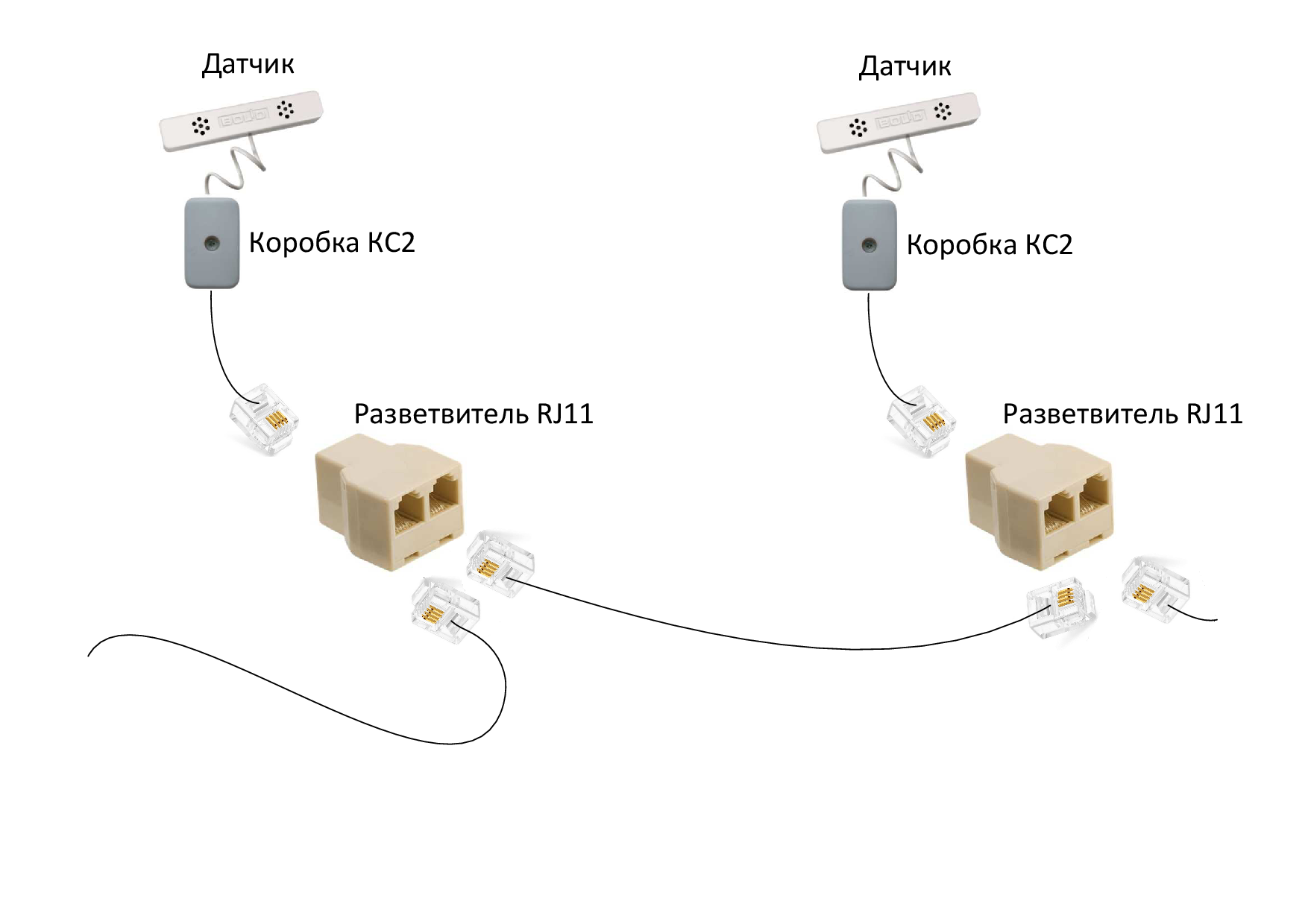

Stand assembly
For the "practical" part a stand was assembled consisting of:
- protocol converter S2000-PP production NVP "Bolid";
- controller S2000-KDL production NVP "Bolid";
- thermohygrometer (combined temperature and humidity sensor) С2000-ВТ manufactured by NVP “Bolid”;
- magnetocontact detector S2000-SMK manufactured by NVP "Bolid";
- leakage point sensor C2000-DZ production "Rielta";
- address extender S2000-AP1 isp. 02 production NVP "Bolid";
- volumetric detector Foton-10M manufactured by "Rielta" (such a "lying around");
- power supply 12V AT-12 / 1.5 DIN manufactured by AccordTec;
- RS-485 / USB adapter purchased on aliexpress (on the popular CH340G chip, linux defines it as “QinHeng Electronics HL-340 USB-serial adapter”). It became interesting how the system will work in the cheapest configuration;
- thin client TONK 1811 from the TONK group of companies (bought on avito for 500 rubles) on an Intel Atom N270 processor with integrated GMA950 graphics.

Refinement of the thin client and the appearance of the stand
Thin client was a bit "finished":
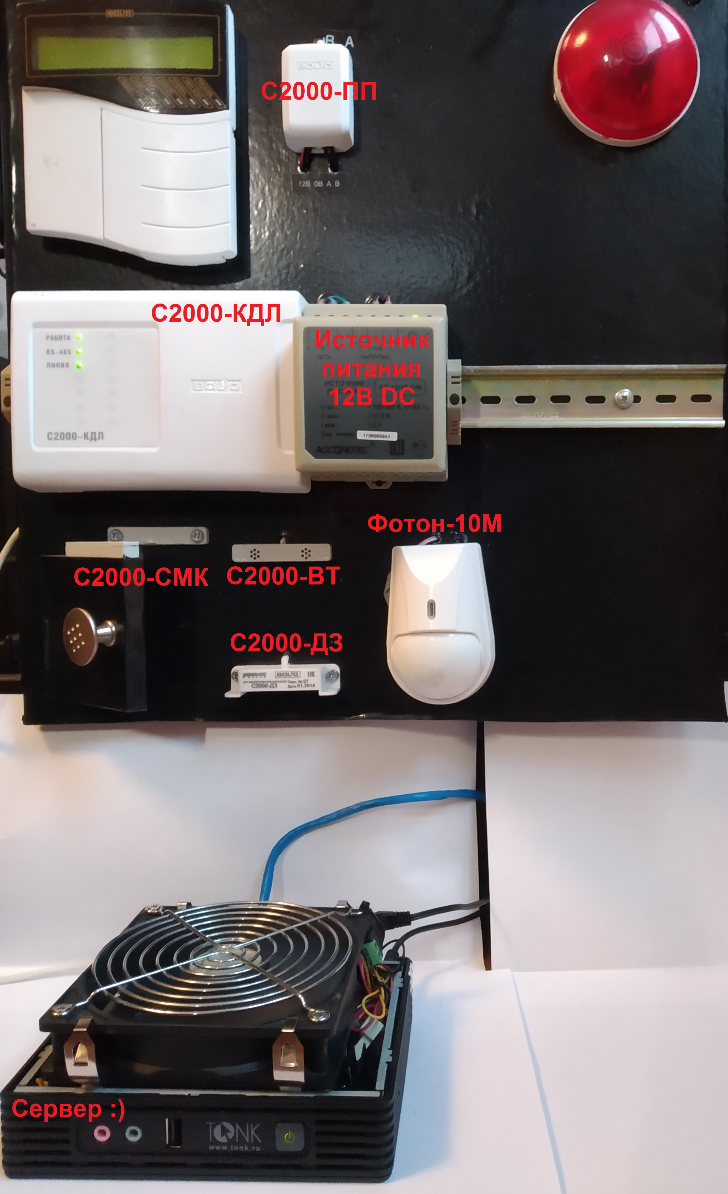
- DOM-модуль на 2Гб с установленным Windows XP embedded заменен на 2,5 HDD ATA 60Гб от старенького ноутбука (пришлось докупить шлейф, SATA-HDD почему-то не подхватился — порт SATA в BIOS включал);
- увеличен размер оперативной памяти DDR2 SO-DIMM с 1Гб до 2Гб;
- установлен Linux Mint 19.1 “Tessa” Xfce Edition и настроен удаленный рабочий стол с помощью TightVNC;
- «доработана» система охлаждения — уменьшил радиатор, чтобы поместился HDD практически «заподлицо» с корпусом, убрал верхнюю крышку и сверху «присобачил» какой-то вентилятор 120 мм, подключенный через резистор. Тут же пропали все «тормоза», стало вполне вменяемо работать.

Setting up the car equipment
All settings are made in the Windows environment, respectively, before starting work, you need to install the driver on the RS-485 / USB adapter, as well as two “super” programs from BHP, which are supplied for free: Orion-prog and Uprog . Next, the devices are separately connected to the RS-485 / USB adapter to the AB RS-485 “Orion” ports (direct layout is used, and not like on COM ports).
IMPORTANT: for all subsequent steps at S2000-PP jumper XP1 on the board should be removed.
Step 1. Insert the RS-485 / USB adapter into the USB connector and see in the device manager which COM port number is assigned to the adapter. Drivers for the adapter must be installed without exclamation marks in the "Device Manager".
Step 2. On behalf of the administrator, launch Orion-prog, select the required COM port and search for and view the firmware version of the device. Go to the manufacturer's official website and check for a more recent firmware and, if necessary (most likely required) - perform an update (at the time of writing this article: for S2000-PP - 1.32, S2000-KDL - 2.22).
Instrument firmware in pictures

* In fact, firmware 1.32 was set “crookedly” - the Uprog configuration was not read from the device. Therefore, "rolled back" back to 1.31.
Step 3. Setting the address at the instruments (first with S2000-PP, for example, 2 and then with S2000-KDL - 3). To do this, run the Uprog - all devices have the default address 127, so you need to configure the devices at the beginning one by one. For more detailed videos from the manufacturer, see YouTube .
Step 4. After setting the address on the S2000-KDL, it is necessary to set the addresses of the sensors in the two-wire communication line (DPLS). They also have the default address 127 (and the circle with the sensor in the Uprog is not highlighted). We read the configuration of the device (Ctrl + F3) and in series connect sensors to the DPLS outputs, setting addresses. When pointing to the sensor in the context menu “Request AU Type”, you can specify the type of sensor or “Request A / D ADC” - find out if the sensor works (for example, for a magnetic-contact detector ADC when closing: 100, and when opening: 50). In fact, I have the following address configuration: 1 - reed switch S2000-SMK, 2 - temperature C2000-BT, 3 - humidity C2000-BT, 4 - leakage C2000-DZ, 5 - address extender S2000-AP1 isp. 02 (with the Foton-10M volume detector connected to it).
Assigning addresses to sensors in pictures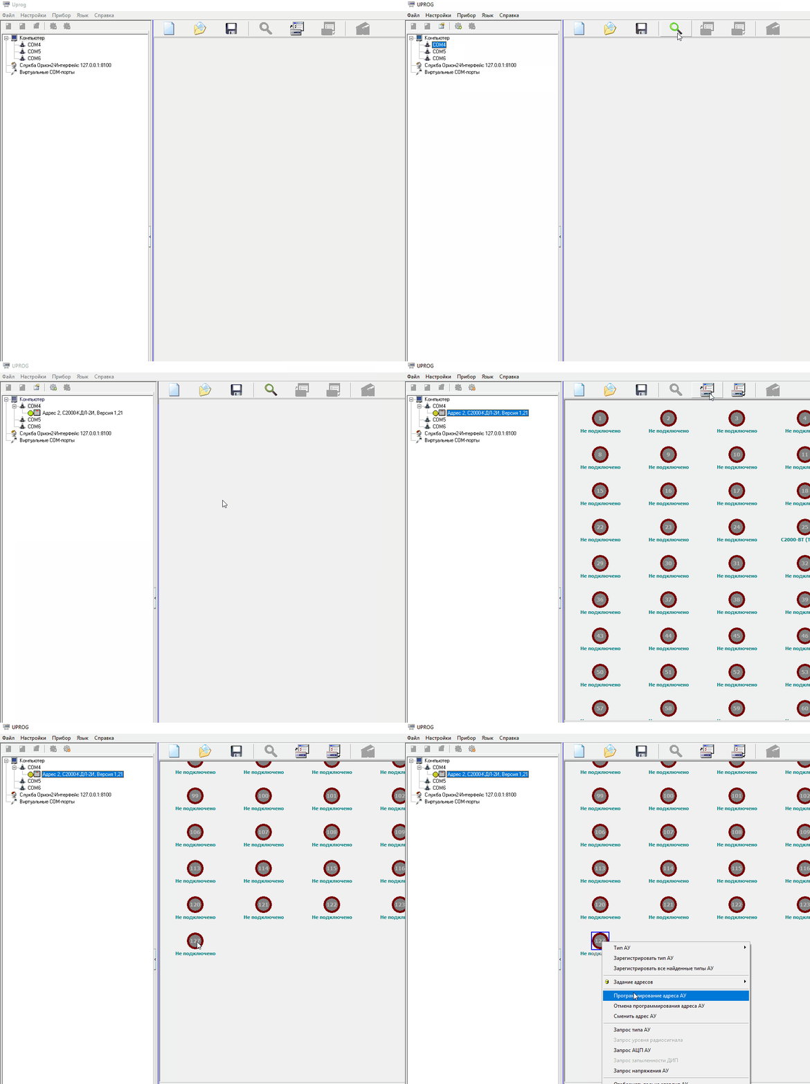

Next, go to the "Inputs" tab and do the following:
- we indicate the types of sensors: for temperature - 10, for measuring humidity - 15, for all others - 6 (technological);
- for technological inputs, we set “Recovery time, s” - this is the time after which the loop will return to the “Norm” state after receiving the “Violation” state. You need to specify a number not less than the polling interval in Zabbix (I took 10 seconds);
- disable “AU display control” (0), “Open circuit and short circuit control” and “Backup battery status monitoring” to simplify setup.
Setup of entrances to S2000-KDL in pictures

After all the “manipulations” with the S2000-KDL, we perform the “Configuration recording in the device”.
Step 5. Configure S2000-PP.
On the tab "Device" settings are shown in the picture (this is the most "running" and on most devices they go by default). Similar settings should be at the COM-port of the RS-485 / USB adapter and any other device connected to the Modbus network. For the S2000-PP device in the Modbus network, I chose address 11 (the address in the Orion system is 2!).

Then go to the tab "Devices" and begin to fill in the "Zone Table":
- I indicated the first column as “3” - this is the address of the S2000-KDL device in the Orion system;
- the alarm number (“alarm loop”) is the address of the sensors (in fact, the LAN = address, we can skip several addresses if we do not want to take information from them);
- Section No. Modbus - you can group our sensors into groups. In order to simplify - I did not do this and attributed 1 section to all;
- zone type is a very important parameter. Choose it according to the type of sensor.

After setting up the S2000-PP, we perform the “Record of the configuration in the device”.
Step 6. We connect S2000-PP and S2000-KDL to the network via RS-485 Orion, connect the sensors to the S2000-KDL (can be a bunch of two terminals), and connect the RS-485 / USB adapter to the Modbus C2000-PP output. The XP1 jumper is installed in the closed position (important: after installing the jumper, the device must be reset by resetting the supply voltage). All - the system is "ready for battle."
We check the "operability" in the free console program Modpoll Modbus Master Simulator (hereinafter - "Modpoll"), for example, at the address of the firmware "S2000-PP" or by returning information from the C2000-KDL to the address "40000" - this is the first sensor:

Firmware "For review" can be downloaded here .
Zabbix configuration
Warning: Zabbix configured for the first time, like Linux Mint (since Zabbix is not available for Windows) :)
After installing Zabbix, you need to install the autoconf , automake , libtool , pkg-config packages and then the extension module - libzbxmodbus . About him on Habré there is a separate article (I will constantly refer to it) and it has recently been updated, just to work with Zabbix 4.0. The article also has more detailed information on the Modbus protocol. The module itself and more or less detailed instructions are on GitHub .
Small differences in installation from that specified on GitHub:
  ...
    ./configure --prefix=/etc/zabbix --enable-zabbix-3.2
  ...
    sudo make install
Studying the work of the libzbxmodbus module, it became clear that using the S2000M remote control circuit would not work, because in this case, receiving data from the thermohygrometers looks like this: writing the number of the required zone to the register 46179 and then taking the data from the register 46328 - that is, very nontrivial (in “large” SCADA systems, this is possible, for example, in MasterSCADA).
Register in the configuration file etc / zabbix / zabbix_server.conf links to the extension and connect the "hardware" to the "server" with Zabbix. I didn’t have to install drivers for the RS-485 / USB adapter, but I didn’t understand how to understand which USB number would be used, it’s good that the connection to / dev / ttyUSB0 worked (you can see if the device is detected in the system)lsusb ).
As with Windows, we check with the help of the Modpoll utility (I ran linux i386) that the hardware was connected and the information was available:

Since the article describes the configuration process using the example of Zabbix 2.2 - there’s a slightly different interface, I’ll provide explanations and pictures settings.
Step 1. Create a network node and a group into which our nodes will belong (for example, a node - “Environmental Monitoring” and a group - “Engineering Infrastructure”):
Setup> Network nodes> Create network node> Enter our names> Add 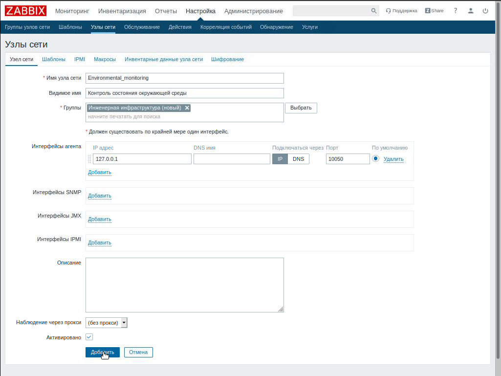
Step 2. Create data items. The article recommends creating templates, but since our system does not contain duplicate elements, I will therefore skip this step. For example, if we had several air conditioners connected via Modbus, then we could use the functionality of the system.
Settings> Nodes> In the line containing the name of our node “Environmental Monitoring” click on “Data Elements”> in the appeared window click “Create Data Item”.
We start to "hammer" our sensors: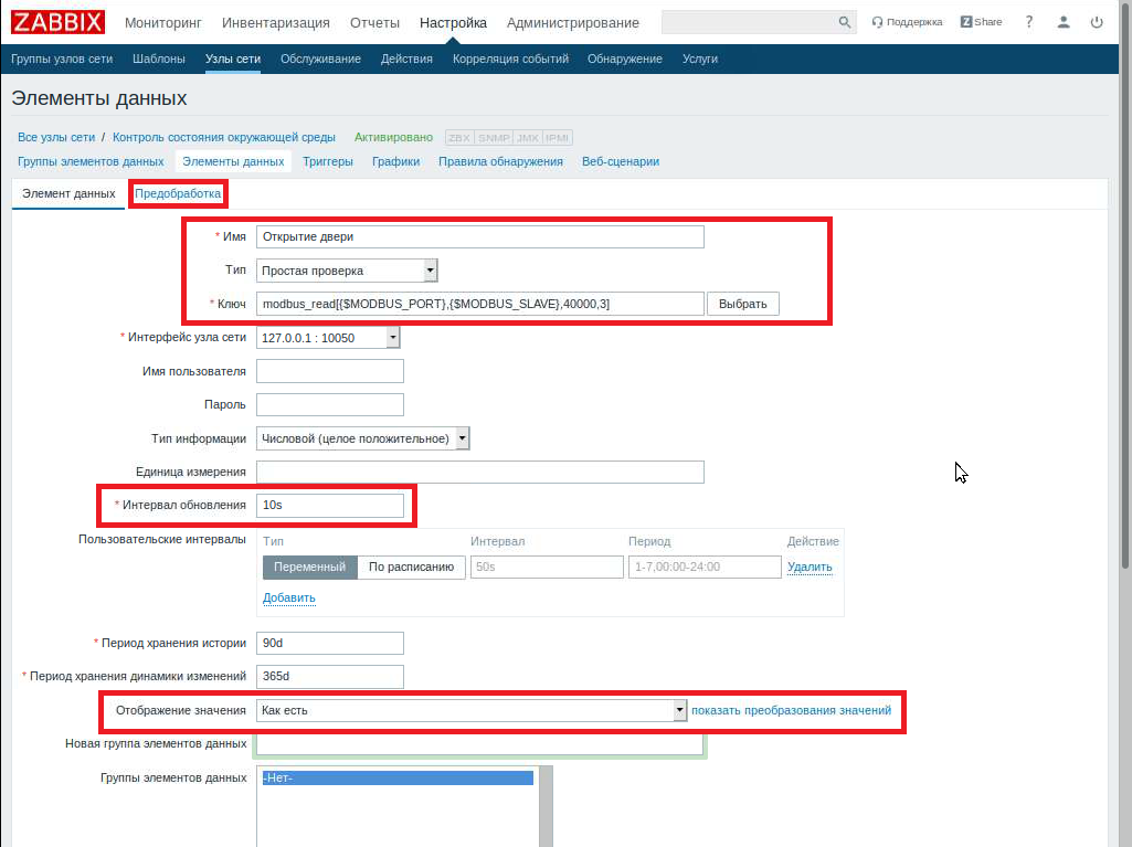
- The article uses the syntax of the “modbus_read_registers” function , and according to the description of GitHub “modbus_read” - the second option is shorter and works;
- instead of macros {$ MODBUS_PORT} and {$ MODBUS_SLAVE}, you can specify the port as / dev / ttyUSB0 and " 11 ", but this will be inconvenient if you later need to change the USB port or S2000-PP address;
- the documentation states that to request a zone status (column "Modbus zone number") on S2000-PP, you need to contact: "register address 40000 + M, where M = (zone number –1)" - this is the way: "zone number minus 1 ";
- do not do very frequent polling by time: S2000-PP will start to return the error “exception error 15” - the device does not have time to prepare the data (this is expressed in the constant light of the indicator on the device);
- for temperature and humidity, data with registers 3000 -...
- in the “Data Elements” window there is also the necessary “Pre-Processing” tab. Here you can edit what will be shown "in the end." Temperature and humidity, is obtained from the read values, which must be divided by 256: "User factor" - 0.0039 (i.e., 1/256);
- For discrete reed switches, leakage sensors, etc. you need to use the "Display values", it is connected with the method of providing information.
Setting data conversion in pictures


It is a little about in what type the data is provided at interrogation of zones.
Suppose we got the answer in decimal format 9148 (D). Let us translate into hexadecimal format (HEX): we get 23BC - according to the instructions for the S2000-PP device, these are two events with codes 23 (HEX) / 35 (D) and BC (HEX) / 188 (D). Next, we go look at Table 5. "List of events (states of the loop) of the Orion system". In it we find, 35 "Restoration of a technological input" and 188 "Restoration of communication with an entrance". There is no need to translate D-HEX-D, the first event is the integer part of dividing the obtained value by 256, and the remainder is the second event ( 9148 = 35 * 256 + 188). When polling technological inputs, we will take away only the first event (priority), which “must” take states 35 and 36 (“Restoration of the technological input” and “Violation of the technological input”). We will discard the fractional part (the second event) using the setting of the Data Element “Information Type: Numeric (positive integer)”.
Step 3. Fill in port macros and device numbers:
Setup> Network Nodes> “Environmental Monitoring”> select “Macros”

Step 4. Displaying readings to the control panel:
Start screen> All panels, select "Create panel"> in the appeared window set "Panel name" and the user to whom this panel will be available> Click "Create new widget"> Type "Data view", Update interval "10 seconds", Groups nodes Engineering Infrastructure> Add> Adjust Panel Size and click “Save Changes”:

Conclusion
The resulting system, through the use of "long-range" protocols, can be an excellent solution, both for monitoring the server and a pair of cross, office zones (in terms of monitoring the provision of a temperate-humidity regime) or even a small data center. Someone may say “fu-fu-fu, the car is still that nasty thing, you need to use XXX (to substitute something from the industrial automation)” is also an option, but in my opinion it will be much redundant and also more expensive . And a small nuance: as you can see, the system on the car is quite simple (although there is some strange logic), but to “finish” the decision on the prom. controllers - sometimes he is still a “headache”.
PS This article is an adaptation of two articles on my blog:
Inexpensive monitoring for the server room (part 1 - introductory)
Inexpensive monitoring for the server room (part 2 - practical)
UPD. Adapter RS485-USB after working for 3 days - fell off. It is recognized as unstable, but suitable for commissioning. It was replaced with a single-port MGX MB3170 converter manufactured by MOXA (taken from what was on hand) - everything became stable.
You need to understand that this article is just an example of how to make friends with Zabbix and Bolid. For a real implementation, you can add more monitored DPLS states, as well as, for example, negative temperatures (they are processed a little differently).
