Key parameters and certification of optical SFP modules
The knowledge of some principles easily compensates for the ignorance of some facts.
Helvetius
Optical transceivers
Currently, the use of optical technologies in the construction of telecommunication networks has become almost universal. Everyone who dealt with optical switching or transmitting equipment encountered the operation of optical transceivers - transceivers (English transceiver = transmitter + receiver).
Transceivers are designed to convert electrical signals into optical signals for subsequent transmission via a fiber optic line and subsequent optoelectronic conversion at the reception. At the initial stage of the development of fiber optics, transceivers were mounted on printed circuit boards of active equipment. Subsequently, with the growth of the range of such devices (switches, routers, multiplexers, media converters), it became necessary to separate the parts responsible for processing information and for transmitting it (in fact, pairing with the optical line).
In the last 10-15 years, optical transceivers are compact interchangeable modules designed for various parameters of transmission lines and installed in standardized electrical ports of active equipment. This allows you to optimize costs in the design, and especially in the reconstruction of optical networks. For example, it is possible to increase the speed, transmission range, increase the amount of transmitted information through the use of spectral multiplexing systems (WDM, CWDM, DWDM). Or, let’s say, to use different types of transceivers for remote subscribers in the same switch.
Now the most popular standard for interchangeable optical transceivers are SFP modules (Small Form-factor Pluggable). They are small-sized constructions in a metal case (for mechanical protection and electromagnetic shielding) with leads for connecting to slots of active equipment. There are also two optical ports in the module: an emitter (Tx) and a photodetector (Rx) for operating in two-fiber mode. In single-fiber SFPs, there is only one optical port, and the direction of transmission and reception is divided inside the module using the built-in WDM multiplexer (BOSA, Bidirectional Optical Sub-Assemblies). In this case, the transceivers work in pairs at two wavelengths.
On the module board, in addition to the emitter and photodetector, there are schemes for providing the emitter pump current, conversion to a linear code, displacements on the photodetector, thermal stabilization, etc.

Fig. 1. Block diagram of a replaceable optical transceiver
- TIA - transimpedance amplifier;
- LimA - limiting amplifier;
- DDM - digital diagnostic module;
- EEPROM - ROM with module parameters;
- O / E - optoelectronic converter;
- E / O - electron-optical converter.
All modules support HotSwap during operation. In most modern designs, the Digital Diagnostics Monitoring (DDM) function is implemented, which allows you to control the internal temperature, power supply voltage, laser bias current, laser output power, and received optical signal level from an external terminal.
Geometrical dimensions, mechanical parameters, power supply, parameters of electrical interfaces and other module data are specified in the MSA SFF-8704i specification.
As for the parameters of the optical interface, they are described in a rather generalized form in the standards for Ethernet networks: 802.3u (100BASE-X), 802.3ae (1000BASE-X), 802.3ae (10GBASE-X) and others.

Tab. 1. Ethernet Optical Interface Standards
* The interface is not standardized, but is actively used in the market.
** According to some sources - up to 100 km.
The SFP standard provides for the transfer of information at a speed of 1 Gbit / s with the possibility of transmitting 100 Mbit / s or only 100 Mbit / s. To transfer higher-speed streams, SFP + (10 Gbit / s), XFP (10 Gbit / s), QSFP + (40 Gbit / s), CFP (100 Gbit / s) were further developed. However, at higher speeds, signals are processed at higher frequencies. This requires a larger heat sink and, consequently, large dimensions. Therefore, in fact, the SFP form factor has been preserved only in SFP + modules.
In this article, we will only talk about the parameters of the most popular SFP, SFP + and XFP modules now, since transceiver models at speeds of more than 10 Gb / s are a separate and quite interesting question.
Here we, without pretending to be complete material and without giving mathematical calculations, consider, first of all, the system of parameters of the optical interfaces of the transceiver modules. Understanding the essence of the parameters will allow you to correctly design the segments of the optical networks: choose the optimal parameters of the emitter and photodetector at minimum cost.
Optical Emitter Parameters
Type of emitter (Transmitter type).
As a rule, laser diodes are used as emitters, the type of which depends on the type of fiber, as well as the required power and narrowband. Fabry-Perot (FP) lasers are distinguished by average power, a wide spectrum of radiation and relatively low cost (Fig. 2). They are used with single-mode (at a wavelength of 1310 nm, less often - 1550 nm) and multimode fibers (at wavelengths of 850 nm and 1300 nm) with line lengths from several hundred meters to several kilometers and transmission speeds of 100 Mbit / s and 1 Gbit / s from. Vertical Emitting Lasers (VCSELs) have been developed for local optical networks. They are notable for their low cost, narrow spectrum and work, as a rule, with multimode fibers at a wavelength of 850 nm when transmitting 1 Gbit / s and 10 Gbit / s streams over distances of several hundred meters. Dynamic single-mode distributed-feedback (DFB) lasers have a narrow spectrum at medium and high power. The production technology with suppression of the side modes of radiation determines a higher cost than the two previous types of lasers. They are designed to work with single-mode fibers at wavelengths of 1310 nm and 1550 nm, when transmitting information at a speed of 1 Gbit / s, 10 Gbit / s or more over distances of tens of kilometers (with amplifiers - several hundred kilometers). Such emitters are also used in CWDM systems. The most complex and expensive lasers with an external resonator (EML) are characterized by an extremely narrow spectrum. This is fundamentally important when transmitting high-speed streams (10 Gbit / s, 40 Gbit / s, 100 Gbit / s) over long distances, especially at a wavelength of 1550 nm, where the fibers have a sufficiently large chromatic dispersion. EML narrowband lasers are also used in CWDM and DWDM spectral multiplexing systems. It should be noted that manufacturers do not always indicate the type of emitter in the specifications.
Fiber type
To transmit optical signals, as a rule, two main types of fibers are used: multimode (MM) and single-mode (SM). Accordingly, the emitter and photodetector of the optical transceiver should be designed to work with one of these two types of fibers. This is usually reflected in their labeling and technical specifications. Features of fiber types (for example, OM3, OM4 for multimode or DS, NZFSF, BIF for single mode) should not be taken into account. Another thing is that the attenuation coefficient, chromatic dispersion coefficient, broadband coefficient (only for MM) and other parameters of the used fiber types must be taken into account when calculating the power budget, total dispersion, line length, etc.
The number of optical ports.
Two ports in optical fiber transceivers use two ports: an optical emitter (Tx, Transmitter) and a photodetector (Rx, Receiver). Such modules use two fibers and one working wavelength to transmit in two different directions. Recently, single-fiber transceivers with one optical port have been used much more often. They work, which is called "paired": transmission in two different directions along one fiber goes at two working wavelengths. Transmission and reception signals are separated inside the module using the built-in WDM multiplexer.
Type of optical connector (Connector type).
A variety of types of connectors can be used to connect to the optical line. Small Ethernet connectors such as LC (in dual-fiber and single-fiber modules), as well as SC (only in single-fiber modules) are currently the most popular Ethernet networks.
Spectral Width (Max. Spectral Width).
This rather important parameter depends on the type of emitter. The greater the width of the spectral line, the greater the total chromatic dispersion in the line (Total chromatic dispersion). For multimode fiber communication systems, intermode dispersion is prevailing; therefore, less expensive and wider emitters such as FP or VCSEL are often used there. Since they have a linear spectrum (Fig. 2), the mean square spectral width (RMS) is normalized for them, which is about 3 ... 5 nm for FP and 0.5 ... 1 nm for VCSEL. DFB and EML lasers have one pronounced lobe (one longitudinal mode) in the spectrum and an internal structure for suppressing other (side) modes. Therefore, their spectrum is determined by the central lobe at the level of -20 dB. For DFB, it is 0.1 ... 0.5 nm, and for EML - about 0.01 ... 0.08 nm.
Side Mode Suppression Ratio (SMSR).
This parameter applies only to DFB and EML lasers. It shows how much dB the amplitude of the first side mode (lobe) is less than the amplitude of the central longitudinal mode (see figure [Spectra of emitters]). Thus, a numerical characteristic of the quality of the selectivity of the emitter cavity is given. Typically, the minimum SMSR is normalized to 30 dB.

Fig. 2 Typical spectra of laser emitters of various types.
Transmitter Central Wavelength.
This is the wavelength at which the highest radiation power is transmitted. For lasers such as DFB and EML, it practically coincides with the peak wavelength. Usually, wavelengths of local attenuation minima (“transparency windows”) in optical fibers are used to transmit signals: 850 nm or 1310 nm for multimode fibers; 1310 nm or 1550 nm - for single mode. For CWDM, DWDM optical transceivers, the wavelength corresponds to the frequency grid specified in ITU-T Recommendations G.694.2 and G.694.1, respectively (see table 2).

Tab. 2. Wavelengths of optical transceivers CWDM
Maximum and minimum emitter power (Max./Min Average output power, Mean launched power).
The average power level at the output of the emitter, i.e. power injected into the fiber. Medium - this is not the peak level. As a rule, two values are given in the specifications: maximum and minimum. The technology for the production of optical emitters (TOSA, Transmitter Optical Sub-Assemblies) implies some variation in parameters. The actual power output will be between the maximum and minimum values. But when calculating the power budget in the line, it is precisely the minimum value of the average power that should be taken into account.

Fig. 3. The power levels of optical signals when transmitting them through the
Eye-pattern (Eye pattern).
It is a graphic representation of a digital signal that allows you to evaluate the quality of transmission. It is the result of superposition of all pulses of a real sequence on the clock interval. The overlapping of impulses “1” and “0” forms, in fact, the “eye” (Fig. 4). Its vertical opening is determined by the unit and zero levels, and its horizontal extension is determined by the rise (Rise Time) and fall (Fall Time) pulses. Since the shape of the output signals is probabilistic, the resulting eye is always somewhat blurred. To normalize the eye diagram, a special template (Eye pattern mask) is provided, in which all variations must fit.
International standards (ITU-T G.957, IEEE 802.3) prescribed formalized parameters of type X and Y that define the boundaries of the elements of the template. Maintaining the correct waveform at the receiving side is crucial. However, the presence of interference with the transmission of signals along the line leads to a reduction in the area of the aperture of the eye. The distortions in amplitude are determined by the resulting distortions due to intersymbol transitions, superposition of the power of the reflected pulses, non-ideal characteristics of the amplifiers, etc. Reductions of the aperture arise due to dispersion distortions, jitter, and other factors affecting the distortion of the pulse fronts. Amplitude and temporal distortions can also lead to the fact that at the receiving device the moment and level of decision-making on compliance with “1” or “0” will not be optimally selected.

Fig. 4. Eye diagram of the output optical signal
Amplitude of the optical modulated signal (Optical Modulation Amplitude, OMA) and Pulse damping coefficient (Extinction Ratio, ER).
Both of these parameters characterize the magnitude of the “eye” opening in the eye diagram. The difference is that OMA characterizes the difference of the optical power levels “1” and “0” in relation to their absolute values (in dB or mW), and ER characterizes the ratio of these levels to each other (as a dimensionless quantity or in dB). After the signal passes through the optical transmission line, the signal amplitude decreases, and OMA decreases. And since the ratio levels of “1” and “0” decrease, their ER ratio remains virtually unchanged. These parameters are important for estimating the reception error rate. With their help, such a characteristic is calculated as the deterioration of the signal quality at the reception due to a decrease in the pulse power (Power Penalty). The real minimum ER values are usually 8.2 ... 10 dB for transceivers 100 Mbit / s and 1 Gbit / s.
For high speeds and small distances, lower values are specified - 3.5 ... 5.5 dB. Despite the fact that a larger value of ER implies better conditions for the recognition of signals at the reception, it is quite difficult technically to ensure a large difference in the levels of “1” and “0” at the output of the transmitter. A higher upper level is limited by the temperature regime of the radiation source. And lowering the level of "0" will complicate its recognition at the reception.

Fig. 5. Power levels and amplitude of the output optical signal.
Sensitivity of the photodetector (Receiver Sensitivity).
Sensitivity characterizes the minimum level of power received by the photodetector, at which a given value of the error coefficient is still provided. A lower level of sensitivity, of course, allows you to increase the dynamic range of the entire system (Fig. 3). However, at low detectable powers, the intrinsic shot and thermal noise of the photodetector can affect. As a rule, the sensitivity of the photodetector is within the range of -15 ... -21 dB for SFPs calculated on lines several kilometers long, -14 ... -28 dB for lines 20 - 40 km, -32 ... -35 dB for lines 80 - 160 km and -40 ... -45 dB for lines of about 200 km. Keep in mind that the sensitivity of the receiver depends on the transmission speed. For example, for a speed of 10 Gbit / s, sensitivity below -24 dB is practically not found. At low levels of the received signal, avalanche photodiodes are usually used, which, however, introduce quite large noises. To increase the sensitivity, an increase in the sensitive area of the photodetector is required. On the other hand, this limits the speed of the photodiode, as it will increase the time of absorption of charges, as well as increase the delay of the avalanche multiplication.
Photo overload level (Receiver overload).
Shows the maximum power level that can be applied to the photo detector. Exceeding this level will lead to a nonlinear mode of operation and a sharp increase in the error coefficient at reception, and at higher power, to the destruction of the sensitive area of the photodetector. That is, an elementary breakdown of a reverse biased photodiode occurs. Some manufacturers even separate these two states by specifying “receiver overload saturation” and “receiver overload damage”. In any case, you should not experiment with overloads of the photodetector. You should pay special attention to this when assembling the layout of the line “on the table”. If the receiver overload level according to the specification is higher than the permissible minimum transmitter power, it is strictly forbidden to connect the emitter to the photo detector directly with a patch cord. In this case, it is necessary to use an insert - attenuator with attenuation by at least the difference between the two parameters. Typically, the photo detector overload level is within the range of -3 ... + 2 dBm. However, for some modules it can be -8 ... -10 dBm. This value alone does not say anything about the quality of the receiver. You only need to be careful not to burn an expensive module.
Total output jitter (Total Jitter).
The jitter of the phase (jitter) of the optical transmitter is manifested in the shift of the pulse on the clock interval or the shift of the fronts of the pulse. As a rule, the cause of jitter is the non-ideality of the master oscillator and phase locked loop systems. Subsequently, at the reception, this can lead to a shift in the point in time at which a decision is made about the signal level. This desynchronization is especially unpleasant for networks and systems operating in synchronous mode. Ethernet networks are less sensitive to jitter in the transmission. Total jitter is normalized either in units of time (ps), or as part of the clock interval (UI), at which the peak has shifted relative to another peak (pp). A typical requirement is 0.24 UI or 0.35UI for Gigabit Ethernet and 0.21 UI for 10G Ethernet. Some manufacturers also separately specify phase jitter,

Fig. 6. Transmitter Jitter
Minimum Relative Intensity Noise (RIN).
A parameter characterizing the emitter's own noise in a given frequency band. They arise as a result of spontaneous emission of the source and depend on the temperature regime, the ratio of the bias current and the threshold current. The noise power decreases in proportion to the square of the average radiation power. The acceptable value is - 120 ... 130 dB / Hz. The greater the range and transmission speed, the lower the noise density (i.e., a larger absolute value with a minus sign) is desirable to have. For reference, you can add that the emitters for transmitting analog signals (for example, in cable TV networks) are 20 to 30 dB lower.
Loss of reflection from the receiver (Receiver Reflectance, Return Loss, RL).
This parameter shows how much dB the signal reflected from the receiver port is below the signal level applied to this port. Accordingly, the more the reflected (not useful) signal attenuates, the better. Then the parameter becomes larger in absolute value with a minus sign. Typically, RL is specified at -21 ... -28 dB. However, for interfaces designed for short line lengths (type S), the connector on the photodetector side may not contain the receiving fiber in the ferula, but an open area of the photodetector. Then the reflection loss is normalized to -12 ... -14 dB. That is, in fact, the magnitude of the reflected power is indicated at the Fresnel reflection at the glass / air interface. This allows you to reduce the cost of the optical SFP module with acceptable transmission parameters. A similar parameter is sometimes specified for the Transmitter Reflectance port, with approximately the same values in dB. However, it is difficult to measure, and it is not necessary to take into account in the calculations, since we can only be interested in the power of the emitter that is actually introduced into the fiber.
Dynamic range (Attenuation range, AR, Optical link loss).
Shows in dB what signal power loss can be tolerated without loss of transmitted information quality, i.e. without increasing the error rate above a given one. The dynamic range is not always indicated in the specifications of the manufacturers, but is easily calculated as the difference between the minimum allowable power of the optical emitter and the sensitivity of the photodetector. For low transmission speeds and / or small dispersion in the line, it is the dynamic range of transceivers that is the key parameter that determines the maximum transmission distance or the length of the regeneration / amplification section. For example, for transceivers operating at a wavelength of 1550 nm, AR is ~ 14 dB for a 40 km line, ~ 23 ... 24 dB for 80 km, ~ 28 ... 29 dB for 100 km, ~ 32 ... 34 dB for 120 km In general, you can choose the approximate dynamic range of the transceiver yourself,
Permissible Dispersion (Dispersion Tolerance, DT).
Shows the maximum dispersion value that is allowed on the transmission line (or regeneration section), without a significant deterioration in the quality of information. Deterioration occurs due to intersymbol interference (partial overlapping of pulses of adjacent clock intervals) when transmitting a digital sequence of signals. This can lead to transient effects between the channels, as well as to synchronization noise at the reception. Permissible dispersion is specified for transmission over single-mode fibers. In principle, the rms sum of the chromatic and polarization dispersion should be taken into account as valid. But in practice, at speeds up to 10 Gb / s and line lengths up to 100 km, only the first component is significant. Firstly, it is much larger, especially in the wavelength range of 1550 nm. And secondly, the total chromatic dispersion grows in proportion to the line length, and the polarization dispersion increases in proportion to the square root of the length. Permissible dispersion is indicated in ps / nm. If the specified value is divided by the chromatic dispersion coefficient of the fiber in ps / (nm • km), then we can approximately determine the allowable transmission line length, limited by dispersion distortion. This parameter is not always indicated in the manufacturer's specifications, more often for single-wave transceivers operating in the range of 1550 nm or CWDM transceivers in the range of 1470 - 1610 nm. Typical DT values are 800 ps / nm (for lines up to 80 km), 1600 ps / nm - up to 80 km, 2400 ps / nm - up to 120 km. For shorter distances, the variance is usually not standardized. Permissible dispersion is indicated in ps / nm. If the specified value is divided by the chromatic dispersion coefficient of the fiber in ps / (nm • km), then we can approximately determine the allowable transmission line length, limited by dispersion distortion. This parameter is not always indicated in the manufacturer's specifications, more often for single-wave transceivers operating in the range of 1550 nm or CWDM transceivers in the range of 1470 - 1610 nm. Typical DT values are 800 ps / nm (for lines up to 80 km), 1600 ps / nm - up to 80 km, 2400 ps / nm - up to 120 km. For shorter distances, the variance is usually not standardized. Permissible dispersion is indicated in ps / nm. If the specified value is divided by the chromatic dispersion coefficient of the fiber in ps / (nm • km), then we can approximately determine the allowable transmission line length, limited by dispersion distortion. This parameter is not always indicated in the manufacturer's specifications, more often for single-wave transceivers operating in the range of 1550 nm or CWDM transceivers in the range of 1470 - 1610 nm. Typical DT values are 800 ps / nm (for lines up to 80 km), 1600 ps / nm - up to 80 km, 2400 ps / nm - up to 120 km. For shorter distances, the variance is usually not standardized. This parameter is not always indicated in the manufacturer's specifications, more often for single-wave transceivers operating in the range of 1550 nm or CWDM transceivers in the range of 1470 - 1610 nm. Typical DT values are 800 ps / nm (for lines up to 80 km), 1600 ps / nm - up to 80 km, 2400 ps / nm - up to 120 km. For shorter distances, the variance is usually not standardized. This parameter is not always indicated in the manufacturer's specifications, more often for single-wave transceivers operating in the range of 1550 nm or CWDM transceivers in the range of 1470 - 1610 nm. Typical DT values are 800 ps / nm (for lines up to 80 km), 1600 ps / nm - up to 80 km, 2400 ps / nm - up to 120 km. For shorter distances, the variance is usually not standardized.
Transmission degradation due to dispersion (Dispersion Penalty, DP).
This parameter characterizes the deterioration of the signal-to-noise ratio at the reception due to the influence of dispersion on the transmitted signal. The effect is to reduce the signal amplitude and stretch the edges to adjacent clock intervals. Accordingly, the deterioration will be greater, the greater the total dispersion in the line and the smaller the interval. Numerically, DP is determined by the logarithm of the quantity inversely proportional to the product of the coefficient of chromatic dispersion, the width of the spectral line of the source, the length of the line, and the linear transmission speed of the information squared.
Typically, DP is specified for high-speed interfaces that are designed for long transmission lines. An acceptable parameter value is in the range up to 4 dB. Otherwise, you need to do a more accurate calculation of the project based on the resulting noise and take some technical measures. For example, the use of optical or electronic compensation for chromatic dispersion.

Fig. 7. The dependence of the deterioration of transmission quality due to dispersion on the line length at different transmission speeds and the width of the spectral line of the emitter.
Optical Transceiver Certification
First, a few words about the principles of certification. It is widely believed that certification is the control of product quality. In fact, certification is a procedure for confirming certain product parameters, the requirements of certain standards. No more and no less.
The certificate itself contains a list of standards, compliance with which was confirmed by tests, documents, calculations. On the other hand, if, for example, in some AB chain, you have a certificate as evidence of the compliance of the “B” element with its standards, then you can be sure that if the standardized joints “AB” and “B- A ”, then the whole chain will work. And this is already important, for example, for the telecommunications sector, where multicomponent networks and systems are usually used.
Another important useful quality of certification is the conduct of laboratory tests in an accredited independent laboratory. Even with a very high level of production and your complete trust in the manufacturer, it is always useful to conduct external tests. Especially if it is really a test, not an unsubscribe. Firstly, even the “most branded brands” have been seen more than once in non-compliance with standards, although not as often as “artisans” of various stripes. And secondly, the behavior of the tests often allows not only to actually measure the values of the parameters, but also to analyze their margin in relation to the limits provided by the standards. From this margin, in part, one can judge the reliability of a device or system.
That was our goal. Carry out real tests with good attorney devices, get results on the main transmission parameters of FoxGate optical transceivers and get a certificate of conformity for providing it to our customers.
Of course, SFP-modules are not included in the list of mandatory certification, as they are not home appliances or devices with an increased danger of functioning. Therefore, voluntary certification was carried out. However, in order to obtain a UkrSEPRO certificate confirming the possibility of using equipment on public networks in Ukraine, we had to fulfill two conditions. Firstly, the standards used were supposed to comply with the “List of standards and norms that technical equipment for wired telecommunications should use, which are intended for use in the public telecommunication network of Ukraine”. And secondly, the certification body and the testing laboratory must be accredited with the Communications Administration of Ukraine. We chose the testing laboratory "Energosvyaz" (beginning - A. Kolchenko),
Selection of measured parameters
It is natural that during the certification tests not all parameters specified in the technical specifications of manufacturers or in the standards are checked. Some of the parameters are difficult to measure. And this requires specialized and expensive equipment. Moreover, the higher the frequency band (or transmission speed) - the more expensive equipment is required. And the costs of certification and verification, and even considerable funds for the constant confirmation of accreditation, do not contribute to the good equipment of our laboratories with modern measuring instruments.
Sometimes optical measuring equipment of acceptable accuracy is quite large and bulky. Rather, it is suitable for factory conditions, where there is a place for its installation and the appropriateness of its use for flow control.
Therefore, when choosing the scope of tests / measurements, there is always a rational approach:
- conduct as many tests as possible to confirm the standards (and most importantly the principles!) of technical standards;
- Do not go into complex, expensive and long-term trials;
- if possible, conduct tests (not even included in the standards, but specified in the manufacturer’s documents), which would enable the customer to evaluate the operability and reliability of the devices.
Based on this, we agreed with the certifiers on the test program, which, in general, included the main energy parameters of the optical interface (since this is important for calculating the lines), as well as spectral characteristics and an eye diagram, which allow checking the quality of the output signal (important work lines at extreme distances and over time). The characteristics of the electrical interfaces of the transceivers were also tested, but we will not dwell on these results, since they, as a rule, do not cause problems during the operation of optical modules.
The following small-sized optical transceivers of the FoxGate trademark were put up for certification:
- 19 types of SFP modules (100 Mbit / s ... 1 Gbit / s): single-fiber and two-fiber, for multimode and single-mode fibers, for wavelengths 1310/1490/1550/1570 nm, for distances from 3 to 120 km;
- 15 types of SFP + modules (1 Gbit / s ... 10 Gbit / s): single-fiber and two-fiber, for multimode and single-mode fibers, at wavelengths 850/1310/1550 nm, at distances from 0.3 to 80 km;
- 15 types of XFP modules (10 Gb / s): single-fiber and two-fiber, for multimode and single-mode fibers, at wavelengths 850/1270/1310/1550 nm, at distances from 0.3 to 80 km;
- 3 types of SFP CWDM modules (100 Mbit / s ... 1 Gbit / s): two-fiber, for single-mode fibers, at 18 wavelengths according to the ITU-T G.694.1 frequency grid, at distances of 40/80/120 km;
- 3 types of SFP + CWDM modules (10 Gbit / s): two-fiber, for single-mode fibers, for 18 wavelengths according to the ITU-T G.694.1 frequency grid, at a distance of 20/40/70 km;
- 3 types of XFP CWDM modules (10 Gb / s): two-fiber, for single-mode fibers, at 18 wavelengths according to the ITU-T G.694.1 frequency grid, at a distance of 20/40/70 km.
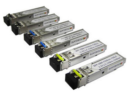
Fig. 8. Optical Transceivers FoxGate
The measurement results of the energy parameters of the optical interface
* The average output radiation power was determined at operating wavelengths using an OT-2-5 optical power meter.

Fig. 9. Measurement of the output optical power of transceivers.
The result was within the range between the specified maximum and minimum values. On average, the measured power exceeded the minimum by 3 ... 5 dB. The minimum margin is 2.3 dB.
* It was very interesting to check the stability of the radiation level of the optical transmitter over time. As a result, it can be noted that when turned on, the emitter enters the mode in a few minutes. After that, the average output power can change by no more than 0.01 dB for 10 minutes (they did not wait longer). Interestingly, the XFP emitters and all three lines of CWDM sources (especially SFP), which were enough for half a minute, entered the mode most quickly.
* The sensitivity of the photodetector was measured using an OT-2-5 optical power meter and a PHOTOM-7081ZA variable attenuator.

Fig. 10. Measurement of the sensitivity of the optical receiver
* Reflection losses at the photodetector were determined using the IVPo device (see Fig. 11). In the process of testing from an internal calibrated source, an unmodulated signal was applied to the photodetector. The reflected signal is returned to the same port, and through the internal coupler it enters the recording photodetector. The results were within the specified values: about 14 dB for modules with open photodetectors and 34 ... 37 dB for detectors with ferula.

Fig. 11. Measurement of reflection attenuation of the optical receiver
* Eye chart analysis was performed using a Tektronix CSA803C telecommunications signal analyzer. This measurement is quite complicated in itself, since a specialized analyzer (oscilloscope) is needed with huge broadband - up to several GHz and several tens of GHz, depending on the speed of the transmitted data stream. In addition, it is important to synchronize this signal and minimize the influence of high-frequency interference and interference. Taking into account the hardware capabilities of the laboratory, the analysis was carried out only for 1 Gbit / s modules. As expected, the eye diagrams at the output of the emitters fit perfectly into the mask.

Fig. 12. Measuring an eye chart at the output of an optical transmitter
* The overload level of the photodetector of most samples was not measured so as not to burn the module. In cases where the overload level was higher than the maximum output level of the emitter, we were convinced of the transceiver operability when connected directly "from output to input".
Spectral Parameter Measurement Results
Certification laboratories are extremely rarely equipped with measuring instruments that allow viewing the spectral characteristics of components in the optical range. Not even new devices, quite expensive. And if we add to this the problems with their metrological certification, the costs of certification and periodic verification, it becomes clear why no one really wants to have such devices on balance.
Pictures of the spectra of all types of optical modules, as well as their spectral parameters, at the Energosvyaz test laboratory were obtained using an Acterna ONT-50 network analyzer in the 1310 nm and 1550 nm ranges, as well as Yokogawa AQ6370 in the 850 nm range.
* The general view of the obtained spectra corresponds to the theoretical (described above) for emitters of types FP, VCSEL, DFB, EML.

Fig. 13. Results of measurements of the spectra of optical emitters
* Pleased with the results of measuring the spectral line width of radiation sources. For FP lasers, the rms spectral width (RMS) was 1.5 ... 1.7 nm with the specified 3.5 ... 4 nm. In addition, the spectrum analyzer automatically calculates the half-maximum spectrum width (FWHM), which for a Gaussian distribution is defined as 2.35 of the RMS spectrum width. DFB lasers showed values of 0.12 ... 0.45 nm at a rate of 1 nm. And the narrowest spectrum was expected to be for lasers with an external modulator (EML) - 0.02 ... 0.08 nm. This allows you to provide a large transmission range even at a speed of 10 Gbit / s without fear of the influence of chromatic dispersion.
* The central wavelength for lasers such as DFB and EML is determined quite easily from the peak value of the fundamental mode of the emitter. For FP and VCSEL lasers, the weighted average wavelength is taken into account, taking into account all the main modes, which may slightly differ from the peak one. The results for all modules were in accordance with the specification. The difference between the wavelength and the nominal one was ± 3 ... 8 nm (normal from ± 10 nm to ± 40 nm) for ordinary SFP, SFP +, XFP without further optical compaction. More stringent requirements are imposed on CWDM optical transceivers: permissible deviation of -6 / + 7.5 nm from the nominal wavelength corresponding to the G.694.2 frequency grid. In measurements, the spread was only ± 0.4 ... 2.4 nm.

Fig. 14. Measurement of spectra at the output of optical transmitters
* The stability of the central wavelength (in time) is not a standardized parameter. However, it, like the stability of the output power, to some extent characterizes the quality of the transmitting part of the module. The drift of the central wavelength ceased for about 20 ... 30 seconds. For CWDM transceivers, stabilization took place in 3 ... 5 seconds.
* The measured coefficient of suppression of the side modes significantly exceeded the norm - 30 dB. DFB lasers had SMSR values within -37 ... -32 dB, and EMLs within -39 ... -50 dB. This indicates a good selectivity of the emitter, i.e. on the quality of manufacturing an internal periodic lattice in a semiconductor structure.
Conclusion
FoxGate optical transceiver certification tests have confirmed that the electrical and optical interface parameters meet international standards. The results obtained for the normalized optical characteristics were within the specified limits, and the margin allowed us to judge the long-term reliable operation of the modules, as well as the possibility of working on transmission lines slightly exceeding the calculated lengths. Additionally, the studied characteristics allowed us to indirectly talk about the high quality of components and assembly, which ensures good reliability of the modules.
The Energosvyaz test laboratory has demonstrated good equipment with modern measuring instruments in the optical range, as well as a high technical and methodological level of training of test engineers.