DVB-S2 on the fingers
It just so happened that in order to write a candidate dissertation I needed to study closely the satellite communications standard DVB-S2 (Digital Video Broadcasting - Setellite, Version 2).
If you, dear reader, are interested in how HDTV or SDTV data is transmitted via one of the most popular satellite television and radio broadcasting protocols and there is no desire / time to read the protocol itself, then please, under cat.

Scheme 1.
Algorithm DVB-S2 (Digital Video Broadcasting - Sputnik, version 2) is intended, as you might guess, for transmitting data via satellite. The standard replaces the DVB-S. It is being developed by the European Telecommunications Standards Institute ( ESTI ). Yes, yes, this is the sameSharashkin office that gave the world GSM and, if anyone knows, TETRA .
Before giving a description of the terrible picture above, I suggest first "in general terms" to understand the basic principle of data transfer.
The picture below is a gross simplification of the data transmission scheme, which is indicated in the protocol itself (see scheme 1).

Scheme 2.
The first thing that happens with the video stream, regardless of which television or radio broadcasting protocol we use, is the connection of all broadcast channels to one channel. How does this happen? Very simple: the fact is that the bandwidth of the satellite channel is significantly greater than that required for a single video stream. Therefore, it is rational to use the so-called Time Division Multiplexing (translated as “ Time Division Multiplexing ” .)
Perhaps you have already met the TDM abbreviation somewhere ... Yeah! in GSM! .. Almost true, only there this principle is called TDMA ( Time Division Multiple Access ).
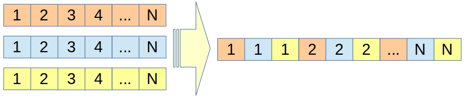
Suppose we have 3 channels (see fig.): Red, Blue, Yellow.I really wanted to take ORT, Rain and NTV, but I remembered that Habr was not a place for politics . Each stream is divided into a sequence of bytes (the so-called time slots ).
The TDM stream is generated in the following way: first the 1st time slot of the Red Channel, then the 1st time slot of the Blue Channel, then the 1st time slot of the Yellow Channel. After that, the second time slot of Red, the second Blue, the third of Yellow, and so on goes to the TDM output.
Scheme 3.
Of course, in practice, I would like to somehow check the information for errors. The DVB-S2 timeslots called UP 's (from User Packet ). CRC-8 in the first diagram is the error detection code.
The second phase in our simple schematic is scrambling. The meaning of scrambling, as I understand it, is to make the probabilities of 1 or 0 occurring equally likely. This is necessary, as the next phase in our simple shemku - the Error Correction Codes (the ECC) ( error correction codes ). Indeed, those who read the Berlicamp can recall that the whole Algebraic Coding Theory is built on the basis of a priori given rule, that 1 is equal to 0. Of course, due to compression, scrambling is probably unnecessary, but apparently the authors decided to leave it ... (who has a different info , please write in comments!)
After ECC, the output is a code word that is fed to the input of the modulator.
After modulation, the modes are fed to a traveling wave lamp ( Wave Tube Amplifer, WTA ).
I hope in general terms it is clear.
Now that we have briefly examined the general scheme (scheme 2), we will continue to eat the elephant in parts. This chapter is about Mode Adaptation (see diagram 1). The DVB-S2 protocol allows you to independently perform TDM conversion from various single input streams ( Single Input Stream (SIS) ), and to accept an input already multi-channel stream, which is previously obtained from the output of any other protocol ( Multiple Input Stream (MIS) ) . Theoretically, if you are a Rockefeller, you can not use TDM at all and transmit only one stream ... True, this is irrational and expensive, but the standard allows this, as indicated by the inscription in a dashed box on the diagram. In this case, we do not need either synchronization ( Input Stream Synchronizer ) or buffering (Buffer ) (with dashed lines in diagram 1), because in the absence of TDM, there is nothing to synchronize, and it makes no sense to buffer.
Merger Slicer is a module that, as the name suggests, “sticks together” UP timeslots between each other.
After Mode Adaptation, as you can see from their scheme 1, Stream Adaptation goes.
Here is a picture from the standard:

Scheme 4.
UP time slots are presented as a single Generic Continous Stream . Then this stream is "cut" into data blocks called Data Field and a BB (Baseband) header is attached to each Data Field .
The header fields are as follows:
After this splitting, there is a scrambling with the Pseudo Random Binary Sequence (PRBS ) Who cares: This sequence is calculated thanks to the LFSR of length 15, given by the associated polynomial 1+ x ^ 14 + x ^ 15 and the initial value: 100101010000000. Those who understood - I am glad, who did not understand - see the picture:
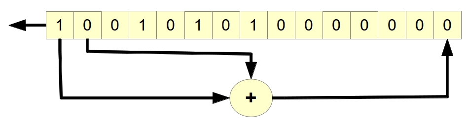
As cryptographers say, “spinning” the LFSR we get the output sequence: 10010101000000010111111000000111000001 ... The minimum length of a sequence until it loops is called a periodLFSR. The period of this LFSR is (2 ^ 15-1). The probability of occurrence of 1 and 0 is 0.5. (In fact, this statement is true not only for the considered LFSR, but for any LFSR filled with not all zeros, provided that the associative polynomial is primitive .)
Coding can be described briefly, or very long. In addition to the main standard [1], there is a coding standard [2]. If habretchiteli have an interest, then I will write a separate article where I will examine in detail the encoding in DVB-S2.
Briefly, the FEC code, as can be seen in diagram 1, consists of three phases:
FEC code works in two modes, the so-called short FECFRAME and normal FECFRAME . The difference in output length. LDPC code block for a short frame 16,200 bytes, for a long 64800 . Normal frames are used to transmit “useful” information (video, radio). For service information, for which time is absolutely critical, use short frames.
But this is not all: for a short frame there are 10 modes with different speeds for BCH and LDPC coding, for the normal 11 options. Altogether 21 variants of the FEC code! For those who are interested in more details, see Table 5a and Table 5b in [2].
Why are there so many coding options? ..
The fact is that there are three modes of satellite operation:
Let's start with a simple one: CCM is the same coding regardless of where the satellite is and what data it transmits. If the interference increased and this was noticed “on the ground”, then until a command to change the encoding is sent (if such a command exists at all), the satellite will not use another encoding.
VCM coding implies different coding for different data types. Well, for example, if a couple of bytes disappears in an uncompressed video stream (although video is usually compressed, of course ...), then there will not be any special problems, if two bytes in the service command are distorted and it is incorrectly received by the satellite, this can lead to epic fail ...
The most interesting is ACM. This mode assumes that depending on the location of the satellite relative to the earth, other satellites, time, the presence / absence of rain, theseasonal flight of cheburashka , the satellite encodes data in different ways.
The DVB-S2 standard supports CCM and ACM. VCM mode without dancing with a tambourine is not supported.
CCM mode is supported for compatibility, but in order to get all the benefits of ACM, you need a different number of possible coding forms! In case of large interference (rain, distance from the earth, interference from other satellites,Cheburashka ), the code speed is low, but it corrects many errors, in case of weak interference, the speed is higher and, therefore, the throughput is higher.
If on the fingers, then after receiving the FEC frame, the data is divided into 2, 3, 4 or 5 bits.
It all depends on what type of modulation you choose:
Thus, two phase modulations (QPSK or 8PSK) and two amplitude phase modulations (16APSK or 32APSK) can be used in DVB-S2. To the one who does not know anything about modulations I recommend a good article by alexxerm . UPDATE (thanks HounD ): You can also view this and this wikipedia article.
Scheme 5.
Mapping means that we “split” the sequence into 2,3,4 or 5 bits.
However, before sending a signal further, we in FL (Physical Layer) introduce a certain synchronizing sequence and scramble again.
After the signal is applied to the traveling wave lamp. Alpha in diagram 1 denotes the “elevated cosine coefficient”, in other words “smoothing coefficient” or, on the Anglo-Saxon mov -off factor .
Here is a picture from VV (only beta is written here instead of alpha):
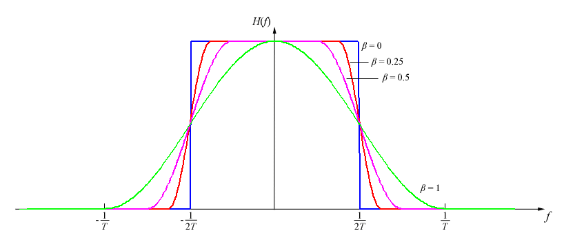
A filter that converts “mapped” data into modes with certain “raised cosine coefficients” is called a BB (baseband) Filter (see diagram 1).
(For those who will analyze the standard: another name in the standard " baseband shaping & quadrature modulation ", so do not be alarmed :))
Actually "on your fingers" this is the whole DVB-S2. Of course, I omitted some details and nuances, but for those who are just curious - these details will quickly fade from my head, and who needs to learn them, it is better to spend Nts evenings and read the standards myself.
To whom the topic is interesting - in comments or in PM. As soon as there is a free minute, I will definitely answer.
PS I thirst for criticism - please comment! :)
[1] Digital Video Broadcasting (DVB) User guidelines for the second generation system for Broadcasting, Interactive Services, News Gathering and other broadband satellite applications (DVB-S2) is the main standard in which a little of everything, and most importantly in the second chapter (Referenses) there are links to all other standards DVB-S2, DVB-S, DSNG, DVB-H and so on.
[2] Digital Video Broadcasting (DVB); Second generation framing structure, channel coding and modulation systems for Broadcasting, Interactive Services, News Gathering and other broadband satellite applications (DVB-S2) - for those who are interested in ATK (Algebraic Coding Theory), I recommend watching this particular standard
If you, dear reader, are interested in how HDTV or SDTV data is transmitted via one of the most popular satellite television and radio broadcasting protocols and there is no desire / time to read the protocol itself, then please, under cat.
Scheme 1.
I - “Rough” scheme.
Algorithm DVB-S2 (Digital Video Broadcasting - Sputnik, version 2) is intended, as you might guess, for transmitting data via satellite. The standard replaces the DVB-S. It is being developed by the European Telecommunications Standards Institute ( ESTI ). Yes, yes, this is the same
Before giving a description of the terrible picture above, I suggest first "in general terms" to understand the basic principle of data transfer.
The picture below is a gross simplification of the data transmission scheme, which is indicated in the protocol itself (see scheme 1).
Scheme 2.
The first thing that happens with the video stream, regardless of which television or radio broadcasting protocol we use, is the connection of all broadcast channels to one channel. How does this happen? Very simple: the fact is that the bandwidth of the satellite channel is significantly greater than that required for a single video stream. Therefore, it is rational to use the so-called Time Division Multiplexing (translated as “ Time Division Multiplexing ” .)
Perhaps you have already met the TDM abbreviation somewhere ... Yeah! in GSM! .. Almost true, only there this principle is called TDMA ( Time Division Multiple Access ).
Suppose we have 3 channels (see fig.): Red, Blue, Yellow.
The TDM stream is generated in the following way: first the 1st time slot of the Red Channel, then the 1st time slot of the Blue Channel, then the 1st time slot of the Yellow Channel. After that, the second time slot of Red, the second Blue, the third of Yellow, and so on goes to the TDM output.
Scheme 3.
Of course, in practice, I would like to somehow check the information for errors. The DVB-S2 timeslots called UP 's (from User Packet ). CRC-8 in the first diagram is the error detection code.
The second phase in our simple schematic is scrambling. The meaning of scrambling, as I understand it, is to make the probabilities of 1 or 0 occurring equally likely. This is necessary, as the next phase in our simple shemku - the Error Correction Codes (the ECC) ( error correction codes ). Indeed, those who read the Berlicamp can recall that the whole Algebraic Coding Theory is built on the basis of a priori given rule, that 1 is equal to 0. Of course, due to compression, scrambling is probably unnecessary, but apparently the authors decided to leave it ... (who has a different info , please write in comments!)
After ECC, the output is a code word that is fed to the input of the modulator.
After modulation, the modes are fed to a traveling wave lamp ( Wave Tube Amplifer, WTA ).
I hope in general terms it is clear.
II - Mode Adaptation
Now that we have briefly examined the general scheme (scheme 2), we will continue to eat the elephant in parts. This chapter is about Mode Adaptation (see diagram 1). The DVB-S2 protocol allows you to independently perform TDM conversion from various single input streams ( Single Input Stream (SIS) ), and to accept an input already multi-channel stream, which is previously obtained from the output of any other protocol ( Multiple Input Stream (MIS) ) . Theoretically, if you are a Rockefeller, you can not use TDM at all and transmit only one stream ... True, this is irrational and expensive, but the standard allows this, as indicated by the inscription in a dashed box on the diagram. In this case, we do not need either synchronization ( Input Stream Synchronizer ) or buffering (Buffer ) (with dashed lines in diagram 1), because in the absence of TDM, there is nothing to synchronize, and it makes no sense to buffer.
Merger Slicer is a module that, as the name suggests, “sticks together” UP timeslots between each other.
III - Stream Adaptation
After Mode Adaptation, as you can see from their scheme 1, Stream Adaptation goes.
Here is a picture from the standard:
Scheme 4.
UP time slots are presented as a single Generic Continous Stream . Then this stream is "cut" into data blocks called Data Field and a BB (Baseband) header is attached to each Data Field .
The header fields are as follows:
- MATYPE determines the type of input data, SIS or MIS, ACM / CCM mode (more on this later) and Roll-off factor
- UPL (User Packet Length) determines the length of the UP'a
- DFL (Data Field Length) defines the length of the Data Field
- SYNC is ... a copy of CRC8 byte
- SYNCCD - indent from the second UP, which, unlike the first UP, is fully included in the Data Field (see Figure 4)
- CRC-8 is ANOTHER verification code (not to be confused with CRC-8 for UPs)
After this splitting, there is a scrambling with the Pseudo Random Binary Sequence (PRBS ) Who cares: This sequence is calculated thanks to the LFSR of length 15, given by the associated polynomial 1+ x ^ 14 + x ^ 15 and the initial value: 100101010000000. Those who understood - I am glad, who did not understand - see the picture:
As cryptographers say, “spinning” the LFSR we get the output sequence: 10010101000000010111111000000111000001 ... The minimum length of a sequence until it loops is called a periodLFSR. The period of this LFSR is (2 ^ 15-1). The probability of occurrence of 1 and 0 is 0.5. (In fact, this statement is true not only for the considered LFSR, but for any LFSR filled with not all zeros, provided that the associative polynomial is primitive .)
IV - FEC (Forward Error Correction) encding
Coding can be described briefly, or very long. In addition to the main standard [1], there is a coding standard [2]. If habretchiteli have an interest, then I will write a separate article where I will examine in detail the encoding in DVB-S2.
Briefly, the FEC code, as can be seen in diagram 1, consists of three phases:
- BCH coding
- LDPC ( Low Density Parity Check ) encoding
- Interleaving
FEC code works in two modes, the so-called short FECFRAME and normal FECFRAME . The difference in output length. LDPC code block for a short frame 16,200 bytes, for a long 64800 . Normal frames are used to transmit “useful” information (video, radio). For service information, for which time is absolutely critical, use short frames.
But this is not all: for a short frame there are 10 modes with different speeds for BCH and LDPC coding, for the normal 11 options. Altogether 21 variants of the FEC code! For those who are interested in more details, see Table 5a and Table 5b in [2].
Why are there so many coding options? ..
The fact is that there are three modes of satellite operation:
- CCM - Constant Coding & Modulation
- VCM - Variable Coding & Modulation
- ACM - Adaptive Coding & Modulation
Let's start with a simple one: CCM is the same coding regardless of where the satellite is and what data it transmits. If the interference increased and this was noticed “on the ground”, then until a command to change the encoding is sent (if such a command exists at all), the satellite will not use another encoding.
VCM coding implies different coding for different data types. Well, for example, if a couple of bytes disappears in an uncompressed video stream (although video is usually compressed, of course ...), then there will not be any special problems, if two bytes in the service command are distorted and it is incorrectly received by the satellite, this can lead to epic fail ...
The most interesting is ACM. This mode assumes that depending on the location of the satellite relative to the earth, other satellites, time, the presence / absence of rain, the
The DVB-S2 standard supports CCM and ACM. VCM mode without dancing with a tambourine is not supported.
CCM mode is supported for compatibility, but in order to get all the benefits of ACM, you need a different number of possible coding forms! In case of large interference (rain, distance from the earth, interference from other satellites,
V - Mapping + PL (Physical Layer) Framing.
If on the fingers, then after receiving the FEC frame, the data is divided into 2, 3, 4 or 5 bits.
It all depends on what type of modulation you choose:
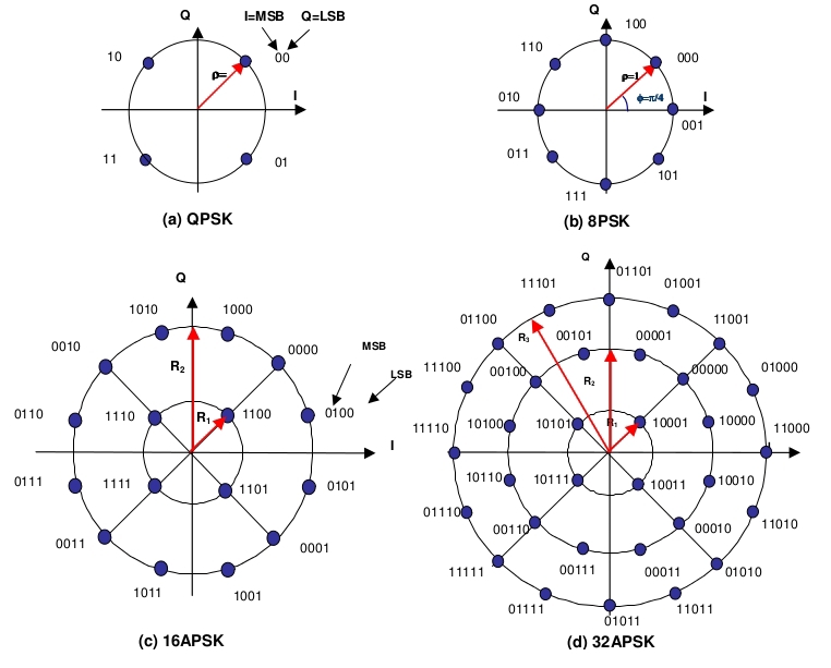
- QPSK (Quaternary Phase Shift Keying) - 2 bits each
- 8PSK (Eigth Phase Shift Keying) - 3 bits each
- 16APSK (Amplitude-Phase Shift Keying) - 4 bits each
- 32APSK - 5 bits each
Thus, two phase modulations (QPSK or 8PSK) and two amplitude phase modulations (16APSK or 32APSK) can be used in DVB-S2. To the one who does not know anything about modulations I recommend a good article by alexxerm . UPDATE (thanks HounD ): You can also view this and this wikipedia article.
Scheme 5.
Mapping means that we “split” the sequence into 2,3,4 or 5 bits.
However, before sending a signal further, we in FL (Physical Layer) introduce a certain synchronizing sequence and scramble again.
VI - BB Filter & Modulation
After the signal is applied to the traveling wave lamp. Alpha in diagram 1 denotes the “elevated cosine coefficient”, in other words “smoothing coefficient” or, on the Anglo-Saxon mov -off factor .
Here is a picture from VV (only beta is written here instead of alpha):
A filter that converts “mapped” data into modes with certain “raised cosine coefficients” is called a BB (baseband) Filter (see diagram 1).
(For those who will analyze the standard: another name in the standard " baseband shaping & quadrature modulation ", so do not be alarmed :))
Instead of a conclusion
Actually "on your fingers" this is the whole DVB-S2. Of course, I omitted some details and nuances, but for those who are just curious - these details will quickly fade from my head, and who needs to learn them, it is better to spend Nts evenings and read the standards myself.
To whom the topic is interesting - in comments or in PM. As soon as there is a free minute, I will definitely answer.
PS I thirst for criticism - please comment! :)
The standards discussed in this article
[1] Digital Video Broadcasting (DVB) User guidelines for the second generation system for Broadcasting, Interactive Services, News Gathering and other broadband satellite applications (DVB-S2) is the main standard in which a little of everything, and most importantly in the second chapter (Referenses) there are links to all other standards DVB-S2, DVB-S, DSNG, DVB-H and so on.
[2] Digital Video Broadcasting (DVB); Second generation framing structure, channel coding and modulation systems for Broadcasting, Interactive Services, News Gathering and other broadband satellite applications (DVB-S2) - for those who are interested in ATK (Algebraic Coding Theory), I recommend watching this particular standard