Build a traffic light: the story of another introduction
Discussing the implementation of auto-testing in our company, the idea of visualizing the results using a traffic light was proposed. This tool is simple and understandable to everyone, and also produces a small wow effect. Under the cut will be the history of the introduction of traffic lights in our system of autotests.
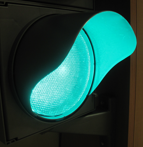
On the Internet, a huge number of proposals for the purchase of traffic lights. We did not bother and collect our own, but immediately bought a finished one.
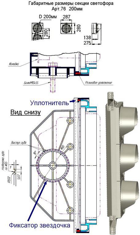
A traffic light is expensive. This model cost us almost 13,000 p. A big plus of such a traffic light is its compactness. The thickness of the traffic light, including visors, is 275 mm. Without visors 138 mm. Length 840 mm. The kit includes brackets with which we hung it on a cabinet ....
To control the traffic light, we decided to use the Quartech - Jackpot - USB discrete input / output board, developed by our friends.
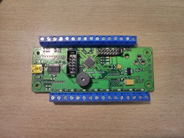
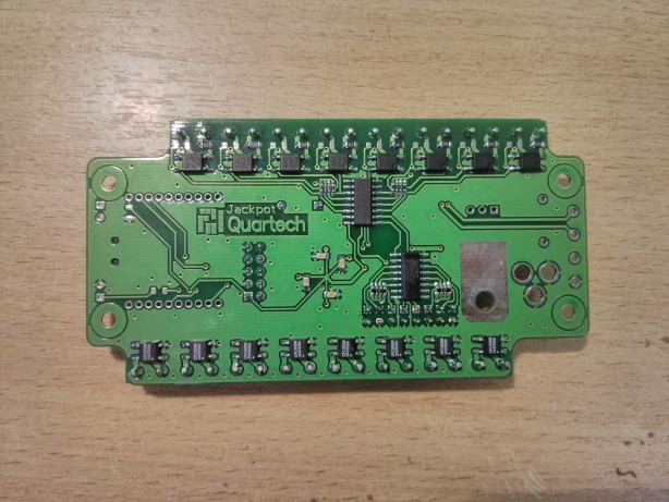
The control board is located in the traffic light housing and controls three COSMO solid-state relays, providing with a large margin not only galvanic isolation, but also the necessary load capacity (if desired, more than a dozen such traffic lights can be controlled through them).

An extensible control protocol was developed and implemented that allows using this board to control not only a traffic light, but also many other peripheral devices (powering surveillance cameras, lighting control systems, various buttons and sensors on demonstration layouts).
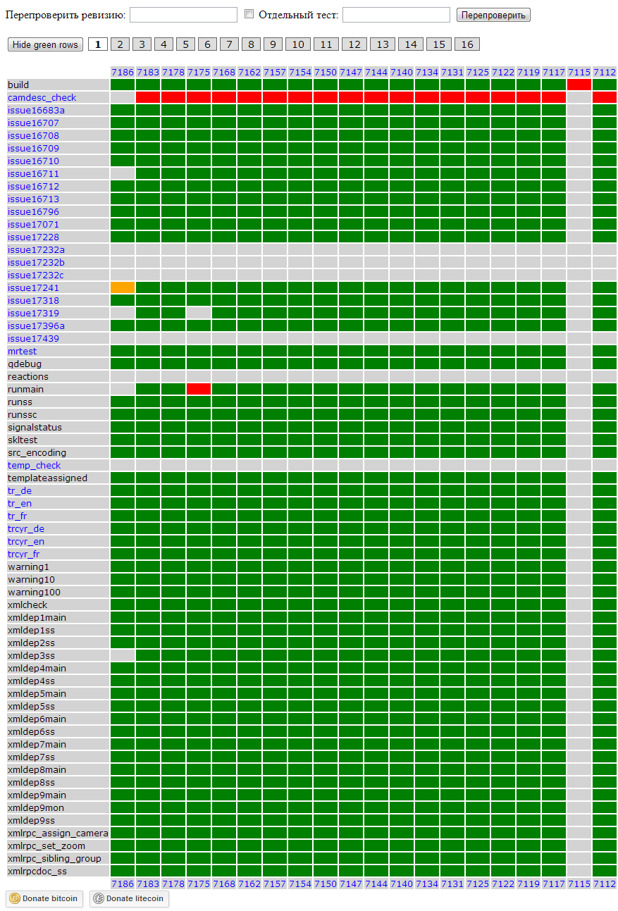
The automated testing system is written in python3. With a frequency of one minute, the presence of a new revision in the repository is checked. If such is present, it is pumped out, and tests are "set" on it. Tests are separate scripts on the same python3, between which there are dependencies. Thanks to the dependencies, the tests are arranged in a certain sequence: first, a test is run that builds the project; followed by "quick" tests; last but not least, everyone else. The test results are placed in the database (sqlite).
A separate script implements a web server that visualizes test results.
The same web server was taught to generate a summary of the set of tests. This feature is used to control traffic lights.
The server address and the list of tests that the traffic light will monitor will be indicated in the configuration file.
The logic of the traffic light in the test system is very simple:
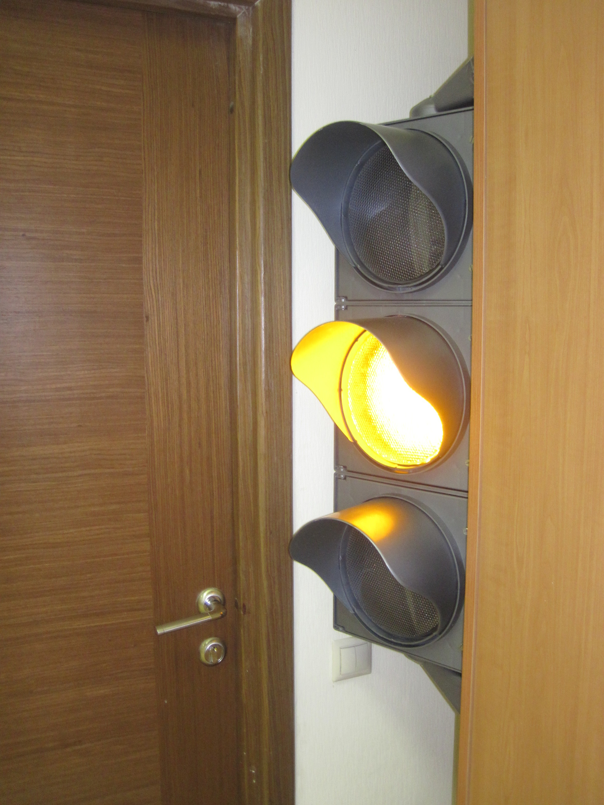
A traffic light was placed before leaving the office. This gives a rather tangible psychological effect: the green traffic light is on - the path is clear (you can safely go home), red - you need to correct the error.
Search and buy traffic light
On the Internet, a huge number of proposals for the purchase of traffic lights. We did not bother and collect our own, but immediately bought a finished one.
Technical characteristics of the transport LED traffic light GOST R 52282-2004:
• Minimum power consumption of a traffic light: no more than 6W (red and yellow section) and 8W (green section) per section;
• Operating voltage: AC 220V, in accordance with GOST 13109. According to tests, the dielectric strength withstands a voltage of at least 1500V with a frequency of 50Hz without breakdowns for 1 min;
• Warranty from the manufacturer for 3 years. The service life of traffic lights is at least 12 years. Long-life energy-saving LED emitters (LEDs) are used. The average life of LEDs is 100,000 hours;
• Operating temperature range of LED traffic lights: from - 60 C to +60 C;
• Lighting parameters of traffic lights, axial luminous intensity of emitters of traffic lights in accordance with GOST R 52282-2004;
• Light traffic light weight not more than 8 kg;
A traffic light is expensive. This model cost us almost 13,000 p. A big plus of such a traffic light is its compactness. The thickness of the traffic light, including visors, is 275 mm. Without visors 138 mm. Length 840 mm. The kit includes brackets with which we hung it on a cabinet ....
Electronics
To control the traffic light, we decided to use the Quartech - Jackpot - USB discrete input / output board, developed by our friends.
The control board is located in the traffic light housing and controls three COSMO solid-state relays, providing with a large margin not only galvanic isolation, but also the necessary load capacity (if desired, more than a dozen such traffic lights can be controlled through them).
An extensible control protocol was developed and implemented that allows using this board to control not only a traffic light, but also many other peripheral devices (powering surveillance cameras, lighting control systems, various buttons and sensors on demonstration layouts).
Management Protocol Description
All exchange is performed in the request-response mode from the PC, or in the streaming mode of data output in a special mode.
USB full duplex through a virtual COM port, open at 9600kb / s.
Exchange between any devices occurs in direct connection mode. All messages at the transport level have a standardized format:
The current status bit field has the following fields:
bit 0: 0 - normal operation, 1 - error
bit 1: 0 - request standby mode, 1 - data streaming mode
Each team consists of the “Team Number” field and the optional “Team Data” field. Even numbers of commands - requests, odd numbers - answers.
If the response to the command is not received during the guard interval, then the connected device is considered lost.
Board output line management.
It is necessary to send a 0x0A command to the virtual COM port with the data corresponding to the required state of the output lines. If you want to send a signal only to the zero line, then in the byte of these commands you need to transmit 0x01. Thus, the whole command will have the following form:
0x7E 0x02 0x00 0x0A 0x01 0x8B
in response to this command, if possible, the board will respond with the 0x0C command with data corresponding to the state of the installed output lines:
0x7E 0x02 0x00 0x0C 0x01 0x8D
or, if it is impossible to execute, will report an error:
0x7E 0x00 0x01 0x7F
Physical level
USB full duplex through a virtual COM port, open at 9600kb / s.
Transport level
Exchange between any devices occurs in direct connection mode. All messages at the transport level have a standardized format:
| Field | Start byte | Team size (number + data) | Current status | Team number | Team Data | Check sum |
| The size | 1 | 1 | 1 | 1 | 0-254 | 1 |
| Value | 0x7E | 1 - 255 0 - error | Bit field that determines the current state of each type of device | 1 - 255 0 - error | Determined by team | The sum of all previous message fields, including the start byte |
The current status bit field has the following fields:
bit 0: 0 - normal operation, 1 - error
bit 1: 0 - request standby mode, 1 - data streaming mode
Team level.
Each team consists of the “Team Number” field and the optional “Team Data” field. Even numbers of commands - requests, odd numbers - answers.
| Team number | Team description | Data |
| 0x01 | Device Type Request | not |
| 0x02 | Device Type Response | 1 byte: 0 - error 1 - measuring part 2 - interface part 3 - PC |
| 0x03 | Serial Number Request | not |
| 0x04 | Serial Number Response | 2 bytes |
| 0x05 | Software Version Request | not |
| 0x06 | Software Version Response | 2 bytes |
| 0x07 | Request version of iron | not |
| 0x08 | Answer version of iron | 2 bytes |
| 0x0A | Setting port status | 1 byte |
| 0x0B | Port Status Request | not |
| 0x0C | Port Status Response | 1 byte |
| 0x0D | Turn on the squeaker, ms | 1-2 bytes |
| 0x0E | Jumper Status Request | not |
| 0x0F | Jumper Status Response | 1 byte |
| 0x10 | Request for input status (optocoupler) | not |
| 0x11 | Input Status Response | 1 byte |
| 0x12 | Request for the number of input edges | 1 byte (input number) |
| 0x13 | Answer the number of fronts of inputs | 5 bytes: 1st byte - input number 2-3 bytes - number of rising edges 4-5 bytes - number of falling edges |
| 0x14 | Batch query of the status of inputs and counters of the number of edges | not |
| 0x15 | Response to a batch request of the status of inputs and counters of the number of edges | 33 bytes: 1st byte - input status 2-17 bytes - number of rising edges 2 bytes per input starting from zero 18-33 bytes - number of falling edges 2 bytes per input starting from zero |
| 0x16 | Resetting Front Counters | No (in response, a 0x15 command is issued with zero counters) |
| 0x20 | Setting Auto Flashing Bits | 1 byte |
| 0x21 | Request for set output flashing bits | not |
| 0x22 | Response of the set flashing bits of the outputs | 1 byte |
| 0x23 | Setting the flashing period of the output | 3 bytes: 1st byte - output number 2-3 bytes - period in ms By default, the period is 500ms. If bytes 2-3 are 0, then the default period is set. |
| 0x24 | Output Flashing Response | 3 bytes (similar to 0x23 command) |
If the response to the command is not received during the guard interval, then the connected device is considered lost.
Example:
Board output line management.
It is necessary to send a 0x0A command to the virtual COM port with the data corresponding to the required state of the output lines. If you want to send a signal only to the zero line, then in the byte of these commands you need to transmit 0x01. Thus, the whole command will have the following form:
0x7E 0x02 0x00 0x0A 0x01 0x8B
in response to this command, if possible, the board will respond with the 0x0C command with data corresponding to the state of the installed output lines:
0x7E 0x02 0x00 0x0C 0x01 0x8D
or, if it is impossible to execute, will report an error:
0x7E 0x00 0x01 0x7F
Testing system
The automated testing system is written in python3. With a frequency of one minute, the presence of a new revision in the repository is checked. If such is present, it is pumped out, and tests are "set" on it. Tests are separate scripts on the same python3, between which there are dependencies. Thanks to the dependencies, the tests are arranged in a certain sequence: first, a test is run that builds the project; followed by "quick" tests; last but not least, everyone else. The test results are placed in the database (sqlite).
A separate script implements a web server that visualizes test results.
The same web server was taught to generate a summary of the set of tests. This feature is used to control traffic lights.
Under the kat, the script code for controlling a traffic light:
#! /usr/bin/env python3
import sys, os, termios, threading, time, http.client
if len(sys.argv)<=1:
    sys.exit("Usage: {0} CONFIG-FILE".format(sys.argv[0]))
exec(open(sys.argv[1], "rt").read())
portfd=os.open(serialport, os.O_RDWR)
# Configure serial port - make it "raw", set 9600 baud rate and 8N1
iflag,oflag,cflag,lflag,ispeed,ospeed,cc=tuple(termios.tcgetattr(portfd))
iflag&=~(termios.IGNBRK|termios.BRKINT|termios.PARMRK|termios.ISTRIP|termios.INLCR|termios.IGNCR|termios.ICRNL|termios.IXON)
oflag&=~(termios.OPOST)
lflag&=~(termios.ECHO|termios.ECHONL|termios.ICANON|termios.ISIG|termios.IEXTEN)
cflag&=~(termios.CSIZE|termios.PARENB|termios.CSTOPB)
cflag|=termios.CS8
ispeed=termios.B9600
ospeed=termios.B9600
termios.tcsetattr(portfd, termios.TCSANOW, [iflag, oflag, cflag, lflag, ispeed, ospeed, cc])
# Current state of traffic light:
# 0 - fail (red light)
# 1 - success (green light)
# 2 - in progress (yellow light)
# 3 - no data (blinking yellow)
state=3
RED=0
YELLOW=1
GREEN=2
def trafficLightControl(light):
    cmd=[0x7E, 0x02, 0xFF, 0x0A]
    if light==RED:
        cmd.append(1)
    elif light==YELLOW:
        cmd.append(2)
    elif light==GREEN:
        cmd.append(4)
    else:
        cmd.append(0)
    cmd.append(sum(cmd)&0xFF)
    os.write(portfd, bytes(cmd))
def controlThreadProc():
    while True:
        if state==0:
            trafficLightControl(RED)
        elif state==1:
            trafficLightControl(GREEN)
        elif state==2:
            trafficLightControl(YELLOW)
        else:
            trafficLightControl(YELLOW)
            time.sleep(1.5)
            trafficLightControl(None)
        time.sleep(1.5)
controlThread=threading.Thread(target=controlThreadProc)
controlThread.start()
def pollThreadProc():
    global state
    connection=None
    while True:
        try:
            if connection is None:
                connection=http.client.HTTPConnection(server)
            connection.request("GET", "/{0}/status?test={1}".format(project, ",".join(tests)))
            r=connection.getresponse().readall()
            state=int(r.decode("ascii"))
        except:
            state=3
            connection=None
        time.sleep(5)
pollThread=threading.Thread(target=pollThreadProc)
pollThread.start()
The server address and the list of tests that the traffic light will monitor will be indicated in the configuration file.
server="192.168.2.245"
project="tvz-win-trunk"
tests=['build', 'xmlcheck', 'qdebug', 'runss', 'runssc', 'tr_en', 'trcyr_en', 'warning1', 'warning10', 'warning100', 'xmldeps', 'issue16683a', 'issue17071', 'issue16796', 'runmain', 'issue17319', 'issue17318', 'issue17396a', 'smartstation_su', 'xmlrpcdoc_ss', 'src_encoding', 'issue17241', 'issue17228']
serialport="/dev/ttyUSB0"
The logic of the traffic light in the test system is very simple:
- Red - test failed
- Yellow - test runs or test rechecking
- Green - all tests completed successfully
- Blinking Amber - No Server Connection
Summary
A traffic light was placed before leaving the office. This gives a rather tangible psychological effect: the green traffic light is on - the path is clear (you can safely go home), red - you need to correct the error.