Fiber Channel Basics
I continue to broadcast on the topic of clarifying the basic concepts of FC SAN. In the comments on the first post, I was reproached for digging deep enough. In particular, he said little about FC itself and nothing about BB credits, IP and multipathing. Multipathing and IP are topics for individual publications, but I will probably continue about FC. Or I'll start how to look.
To begin with, a small terminological digression (inspired again by a comment on a previous post).
Similar to the OSI network model, Fiber Channel consists of five layers. Each level provides a specific set of functions.
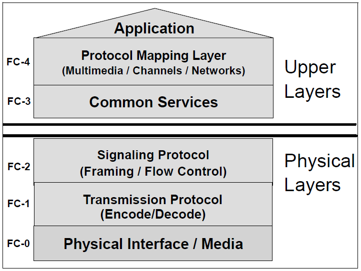
FC-0 is the level of physical interfaces and media. Describes the physical environment: cables, connectors, HBA, transceivers, electrical and optical parameters.
FC-1 - transmission and encoding level. It describes how data will be encoded before transmission and decoded after. At this level, three main functions are defined:
FC-2 - level of framing and signals. It determines the structure and organization of the transmitted information, as well as the control and management of its transmission. Functions carried out at this level:
FC-3 - the level of basic services. The level is laid down for new features that may be introduced in the Fiber Channel in the future. At this level, encryption and compression of data before sending is provided, as well as things like splitting the data stream (striping) in several ways. But I have not encountered implementations of such pieces so far.
FC-4 - protocol mapping level. Describes the protocols that can use FC as a transport and, in fact, the order of use (mapping of these protocols to the lower levels of FC0-3). For a SAN, these can be:
And now more about these and other obscure phrases. In this article, we will consider only the lower three levels, as the most significant when creating and managing the FC SAN infrastructure.
I probably will not give complex tables of varieties of cables, transmitters and their characteristics. Firstly, because it’s inconvenient to insert tables here, and secondly, because these tables are everywhere where at least something is written about FC ( Russian Wikipedia , non-Russian Wikipedia ), and thirdly (and the key one), in my opinion , the main thing is to understand the essence, and finding reference data is not a problem.
And the bottom line is that there are two types of fiber: multimode and singlemode.
Multimode Fiber (MMF)- relatively wide in cross section (50-62.5 microns), intended for short-wave laser beams. “Multimode” means that the light can pass through the channel in different ways - multiply reflected from the walls of the fiber. This makes the cable less sensitive to bending, but reduces the strength and quality of the signal, which limits this type to only small distances - up to 500 m.
Single-mode (Singlemode Fiber, SMF)- a fiber of small diameter (8-10 microns), the signal through which is transmitted by a long-wave laser, the light of which is not visible to the human eye. Here, the light can move in the only way - in a straight line, respectively, the signal is transmitted faster and more accurately, but the equipment for providing such signals is much more expensive, so it is used mainly for communication over long distances (up to 50 km). Single-mode fiber is much more sensitive to kinks and any curvature in general.
Here is a more detailed article about fiber types .
It should be borne in mind that two cables are used to connect two devices. One is used for transmission, the other for reception. Therefore, it is important to connect them correctly (Tx of one side to Rx of the other).
I would also like to mention a term such asdark optics ( dark fiber ). This term does not mean that it is somehow tinted in a special way. These are simply dedicated optical communication lines, as a rule, for long-distance communications (between cities or far-away buildings), which are leased, and for the use of which additional signal amplification equipment is not required (it is provided by the owner). However, since this is just an optical cable, placed at your sole discretion, until you let your light signal pass through it, it remains “dark”.
A smooth transition from FC-0 to FC-1 and vice versa is provided by ASIC - an element of such devices as HBA, disk arrays and switches.
From Wikipedia :
In Fiber Channel equipment, the ASIC consists of the following functional elements:
ASIC
Transceivers, Transceivers, or SFPs — In the case of FC switches, these are separate modules needed to connect a cable to a port. Differ in short-wave (Short Wave, SW, SX) and long-wave (Long Wave, LW, LX). LW transceivers are compatible with multimode and single-mode fiber. SW transceivers - only with multimode. And to both, the cable is connected by an LC connector.
There is also SFP xWDM (Wavelenght Division Multiplexing), designed to transmit data from multiple sources over long distances with a single light beam. To connect the cable to them, the SC connector is used.
The first thing that happens at this level is encoding / decoding information. This is a rather sophisticated process, during which every 8 bits of incoming information is converted into a 10-bit representation. This is done in order to increase control of data integrity, separation of data from service signals and the ability to restore the clock signal from the data stream (maintaining the balance of zeros and ones).
This leads to a noticeable decrease in useful bandwidth, because as you can calculate, 20% of the data stream is redundant overhead. But among other things, official traffic can occupy a considerable part of this stream.
However, the good news is that 8/10 coding is used in 1G, 2G, 4G and 8G equipment. In terms of 10G implementations and starting from 16G, encoding is carried out according to the 64/66 principle, which significantly increases the payload (up to 97% against 80% in the case of 8/10).
In Russian Wikipedia, this term is translated as " ordered sets ." While in my opinion, the word order here should be understood not in the meaning of "order", but in the meaning of "order, command."
To begin with, it is worth mentioning another term used in the context of FC - transmission word - the minimum portion of data for transmission, equal to 4 bytes. If the transmitted information is smaller in volume, then the transmission word is supplemented by special filling bytes (fill bytes), which are cut out on the receiver.
So, ordered sets are special utility transmission words. They are divided into three categories:
When a physical connection is established between ports A and B, the following “metabolism” occurs between them:

All data transmitted in the Fiber Channel environment is divided into frames (frames). The frame structure is as follows:
The spaces between frames are filled with special “filling words” - fill word. Typically, this is IDLE, although starting with FC 8G, the use of ARB (FF) instead of IDLE was standardized, in order to reduce electrical noise in copper equipment (but by default the switches use IDLE).
Most often, the source seeks to transmit much more information to the receiver than 2112 bytes (the maximum amount of data in one frame). In this case, the information is divided into several frames, and the set of these frames is called a sequence. In order to prevent something superfluous from wedging into the logical sequence of frames during parallel transmission, the header of each frame has the fields SEQ_ID (sequence identifier) and SEQ_CNT (frame number in the sequence).
One or more sequences responsible for a single operation is called exchange. A source and a receiver can have several parallel exchanges, but each exchange per unit of time can contain only one sequence. Exchange example: the initiator requests data (sequence 1), the target returns data to the initiator (sequence 2) and then reports the status (sequence 3). Some extraneous set of frames cannot wedge into this sequence set.
To control this process, the header of each frame includes the fields OX_ID (Originator Exchange ID - filled by the initiator of the exchange) and RX_ID (Responder Exchange ID - filled in by the recipient in the response frames by copying the value OX_ID).
Different applications have different requirements for the level of service, delivery guarantee, connection duration and bandwidth. Some applications require guaranteed bandwidth during their operation (backup). Others have variable activity and do not require constant guaranteed channel bandwidth, but they need confirmation in the receipt of each sent packet. To meet these needs and provide flexibility, the FC defines the following 6 classes of service.
For this class, a dedicated connection is established that reserves the maximum bandwidth between the two devices. Requires confirmation of receipt. Requires frames to arrive at the receiver in the same order that they left the source. Due to the fact that it does not allow other devices to use the transmission medium, it is used extremely rarely.
Without a permanent connection, but with delivery confirmation. It does not require matching the order of sent and delivered frames, so they can go through the factory in different ways. Less demanding on resources than class 1, but confirmation of delivery leads to increased bandwidth utilization.
Without a permanent connection and without confirmation of delivery. The most optimal from the point of view of using the factory resources, but assumes that the upper level protocols will be able to collect the frames in the right order and restart the transmission of the missing frames. Most commonly used.
It requires constant connection, confirmation and the order of frames, like class 1. The main difference is that it does not reserve the entire bandwidth, but only part of it. This guarantees a certain QoS. Suitable for multimedia and Enterprise applications that require guaranteed connection quality.
Still not fully described and included in the standard. Previously, a class that does not require a connection, but requires immediate delivery of data as it appears, without buffering on devices.
Class 1 option, but multicast. That is, from one port to several sources.
Class F is defined in the FC-SW standard for use in Interswitch Link (ISL). This is a non-persistent service with delivery failure notifications, used to monitor, manage and configure the factory. The principle is similar to class 2, but that principle is used for interaction between N-ports (node ports), and class F - for communication between E-ports (inter-switch).
In order to prevent the situation when the sender overloads the receiver with an excessive number of frames so that they begin to be discarded by the receiver, FC uses mechanisms for controlling the flow of transmitted data (Flow Control). There are two of them - Buffer-to-Buffer flow control and End-to-End flow control. Their use is regulated by the class of service. For example, class 1 uses only the End-to-End mechanism, class 3 uses the Buffer-to-Buffer, and class 2 uses both of these mechanisms.
The principle of technology - aloan to each house, the sending of any frame should be provided by the presence of a loan to send.
All frames arriving at the port input are placed in a special queue - buffers. The number of these buffers is determined by the physical characteristics of the port. One buffer (queue position) corresponds to one loan. Each port has two credit counters:
TX BB_Credit - transfer credit counter. After sending each frame, it decreases by 1. If the counter value has become equal to zero, transmission is impossible. As soon as R_RDY is received from the receiving port, the counter is incremented by 1.
RX BB_Credit - the counter of credit loans. As soon as the frame is received and placed in the buffer, it decreases by 1. When the frame is processed or sent further, the counter is increased by 1, and R_RDY is sent to the sender. If the counter value drops to 0, then, in principle, the reception of new frames should be stopped. In practice, due to credit synchronization errors, a situation may arise that the source sent one or several frames already after RX BB_credit became zero. This situation is called buffer overflow . In most implementations, the port handles such situations “in a good way” - due to backup buffers. Although some equipment in such cases may link Link Reset.
From here comes the strong impact of port spacing on performance. The higher the distance and the greater the throughput, the more frames will be sent (read the transfer credits spent) even before the recipient receives at least the first one. The situation is facilitated by the architecture of FC switches. The fact is that the number of buffers is not fixed tightly to each port (except eight mandatory), but is common to all. And if “far links” are detected (automatically or manually), the number of buffers allocated by the switch for this port increases. Another plus of shared memory is that you do not need to drive buffers from one port to another inside the switch.
It is implemented by the counter EE_Credit, which determines the maximum frames that the source can send to the receiver without receiving confirmation (Acknowledge, ACK). Unlike BB_Credit, it only applies to data frames, and exchange / accounting occurs between end nodes.
Initially, it seemed to me that the article would be half as much, but during the writing a lot of details surfaced, without which happiness seemed incomplete. I still had to drop a bunch of things that I would like to highlight - the writing process threatened to become endless. If anyone has any comments, suggestions and suggestions about what else is worth writing about, I will be grateful. And thanks to everyone who read to this place.
Materials were used from the following sources:
IBM Redbook “Introduction to SAN and System Networking”
EMC “Network Storage Concepts and Protocols”
Brocade “SAN Fabric Administration Best Practices Guide”
To begin with, a small terminological digression (inspired again by a comment on a previous post).
Fiber or Fiber ?: Initially, Fiber Channel technology was designed to support only fiber optic lines. However, when copper support was added, it was decided to preserve the name in principle, but use the British word Fiber to refer to the standard. American Fiber is retained primarily for sending to fiber.IBM Redbook "Introduction to SAN and System Networking"OriginalFiber Channel was originally designed to support fiber optic cabling only. When copper support was added, the committee decided to keep the name in principle, but to use the UK English spelling (Fiber) when referring to the standard. The US English spelling (Fiber) is retained when referring generically to fiber optics and cabling.
Start
Similar to the OSI network model, Fiber Channel consists of five layers. Each level provides a specific set of functions.
FC-0 is the level of physical interfaces and media. Describes the physical environment: cables, connectors, HBA, transceivers, electrical and optical parameters.
FC-1 - transmission and encoding level. It describes how data will be encoded before transmission and decoded after. At this level, three main functions are defined:
FC-2 - level of framing and signals. It determines the structure and organization of the transmitted information, as well as the control and management of its transmission. Functions carried out at this level:
- Crop (definition of the frame / frame structure) .
- Sequence management
- Exchange Management
- Class of Service
- Flow control
FC-3 - the level of basic services. The level is laid down for new features that may be introduced in the Fiber Channel in the future. At this level, encryption and compression of data before sending is provided, as well as things like splitting the data stream (striping) in several ways. But I have not encountered implementations of such pieces so far.
FC-4 - protocol mapping level. Describes the protocols that can use FC as a transport and, in fact, the order of use (mapping of these protocols to the lower levels of FC0-3). For a SAN, these can be:
- Fiber Channel Protocol for SCSI-3 (SCSI-FCP) - SCSI Forwarding
- Fiber Channel Link Encapsulation (FC-LE) - TCP / IP Forwarding
And now more about these and other obscure phrases. In this article, we will consider only the lower three levels, as the most significant when creating and managing the FC SAN infrastructure.
FC-0
I probably will not give complex tables of varieties of cables, transmitters and their characteristics. Firstly, because it’s inconvenient to insert tables here, and secondly, because these tables are everywhere where at least something is written about FC ( Russian Wikipedia , non-Russian Wikipedia ), and thirdly (and the key one), in my opinion , the main thing is to understand the essence, and finding reference data is not a problem.
And the bottom line is that there are two types of fiber: multimode and singlemode.
Multimode Fiber (MMF)- relatively wide in cross section (50-62.5 microns), intended for short-wave laser beams. “Multimode” means that the light can pass through the channel in different ways - multiply reflected from the walls of the fiber. This makes the cable less sensitive to bending, but reduces the strength and quality of the signal, which limits this type to only small distances - up to 500 m.
Single-mode (Singlemode Fiber, SMF)- a fiber of small diameter (8-10 microns), the signal through which is transmitted by a long-wave laser, the light of which is not visible to the human eye. Here, the light can move in the only way - in a straight line, respectively, the signal is transmitted faster and more accurately, but the equipment for providing such signals is much more expensive, so it is used mainly for communication over long distances (up to 50 km). Single-mode fiber is much more sensitive to kinks and any curvature in general.
Here is a more detailed article about fiber types .
It should be borne in mind that two cables are used to connect two devices. One is used for transmission, the other for reception. Therefore, it is important to connect them correctly (Tx of one side to Rx of the other).
I would also like to mention a term such asdark optics ( dark fiber ). This term does not mean that it is somehow tinted in a special way. These are simply dedicated optical communication lines, as a rule, for long-distance communications (between cities or far-away buildings), which are leased, and for the use of which additional signal amplification equipment is not required (it is provided by the owner). However, since this is just an optical cable, placed at your sole discretion, until you let your light signal pass through it, it remains “dark”.
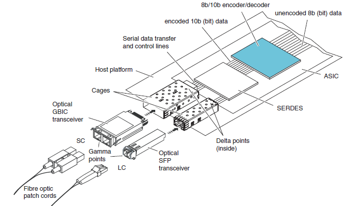
A smooth transition from FC-0 to FC-1 and vice versa is provided by ASIC - an element of such devices as HBA, disk arrays and switches.
From Wikipedia :
ASIC (abbreviation for the English application-specific integrated circuit , "integrated circuit for special purposes") - an integrated circuit specialized to solve a specific problem. Unlike general purpose integrated circuits, specialized integrated circuits are used in a particular device and perform strictly limited functions specific to this device only; as a result, the execution of functions is faster and, ultimately, cheaper. An example of an ASIC is a microchip designed exclusively for controlling a mobile phone, microchips for hardware encoding / decoding audio and video signals (signal processors).
In Fiber Channel equipment, the ASIC consists of the following functional elements:
- Encoder / Decoder - provides encoding of every 8 bits of transmitted data in a 10-bit representation. And decoding back received data.
- SERDES (Serializer / Deserializer) - converts a parallel stream of 10-bit pieces of data into a serial stream of 10-bit pieces of data.
- Transceiver - converts electrical impulses into light signals.
ASIC
Transceivers, Transceivers, or SFPs — In the case of FC switches, these are separate modules needed to connect a cable to a port. Differ in short-wave (Short Wave, SW, SX) and long-wave (Long Wave, LW, LX). LW transceivers are compatible with multimode and single-mode fiber. SW transceivers - only with multimode. And to both, the cable is connected by an LC connector.
There is also SFP xWDM (Wavelenght Division Multiplexing), designed to transmit data from multiple sources over long distances with a single light beam. To connect the cable to them, the SC connector is used.
FC-1
8/10 and 64/66
The first thing that happens at this level is encoding / decoding information. This is a rather sophisticated process, during which every 8 bits of incoming information is converted into a 10-bit representation. This is done in order to increase control of data integrity, separation of data from service signals and the ability to restore the clock signal from the data stream (maintaining the balance of zeros and ones).
This leads to a noticeable decrease in useful bandwidth, because as you can calculate, 20% of the data stream is redundant overhead. But among other things, official traffic can occupy a considerable part of this stream.
However, the good news is that 8/10 coding is used in 1G, 2G, 4G and 8G equipment. In terms of 10G implementations and starting from 16G, encoding is carried out according to the 64/66 principle, which significantly increases the payload (up to 97% against 80% in the case of 8/10).
Ordered sets
In Russian Wikipedia, this term is translated as " ordered sets ." While in my opinion, the word order here should be understood not in the meaning of "order", but in the meaning of "order, command."
To begin with, it is worth mentioning another term used in the context of FC - transmission word - the minimum portion of data for transmission, equal to 4 bytes. If the transmitted information is smaller in volume, then the transmission word is supplemented by special filling bytes (fill bytes), which are cut out on the receiver.
So, ordered sets are special utility transmission words. They are divided into three categories:
- Frame Separators (Start-of-Frame, SOF and End-of-Frame, EOF).
- Two basic signals - IDLE (the port is ready to receive or transmit data) and R_RDY (receiver ready - the port has released a buffer for receiving the next portion of data)
- Basic sequences (primitive sequences):
- NOS (Not Operational) - port detected a disconnect / no connection
- OLS (Offline State) - the port initiates the establishment of a connection, or the port received NOS, or the port goes into off-line state
- LR (Link Reset) - Initialize the connection reset. Dispatched if an OLS is received or any receive-transmit errors occur (usually at the Flow Control level). The sending port clears its buffers and their counters.
- LRR (Link Reset Response) - response to LR. The sending port clears its buffers and their counters.
Link initialization
When a physical connection is established between ports A and B, the following “metabolism” occurs between them:
FC-2
Frames (Frames)
All data transmitted in the Fiber Channel environment is divided into frames (frames). The frame structure is as follows:
- SoF - 4 bytes (1 tw) - identifier of the beginning of the frame.
- Header - 24 bytes (6 tw) - header. It contains information such as source and receiver address, frame type (FT-0 - control or FT-1 - data), sequence number and frame serial number in it, and other control information.
- Data - 0-2112 bytes (0-528 tw) - directly data (for example, SCSI-commands).
- CRC - 4 bytes (1 tw) - checksum.
- EoF - 4 bytes (1 tw) - identifier of the end of the frame.
The spaces between frames are filled with special “filling words” - fill word. Typically, this is IDLE, although starting with FC 8G, the use of ARB (FF) instead of IDLE was standardized, in order to reduce electrical noise in copper equipment (but by default the switches use IDLE).
Sequences
Most often, the source seeks to transmit much more information to the receiver than 2112 bytes (the maximum amount of data in one frame). In this case, the information is divided into several frames, and the set of these frames is called a sequence. In order to prevent something superfluous from wedging into the logical sequence of frames during parallel transmission, the header of each frame has the fields SEQ_ID (sequence identifier) and SEQ_CNT (frame number in the sequence).
Exchange
One or more sequences responsible for a single operation is called exchange. A source and a receiver can have several parallel exchanges, but each exchange per unit of time can contain only one sequence. Exchange example: the initiator requests data (sequence 1), the target returns data to the initiator (sequence 2) and then reports the status (sequence 3). Some extraneous set of frames cannot wedge into this sequence set.
To control this process, the header of each frame includes the fields OX_ID (Originator Exchange ID - filled by the initiator of the exchange) and RX_ID (Responder Exchange ID - filled in by the recipient in the response frames by copying the value OX_ID).
Classes of Services
Different applications have different requirements for the level of service, delivery guarantee, connection duration and bandwidth. Some applications require guaranteed bandwidth during their operation (backup). Others have variable activity and do not require constant guaranteed channel bandwidth, but they need confirmation in the receipt of each sent packet. To meet these needs and provide flexibility, the FC defines the following 6 classes of service.
Class 1
For this class, a dedicated connection is established that reserves the maximum bandwidth between the two devices. Requires confirmation of receipt. Requires frames to arrive at the receiver in the same order that they left the source. Due to the fact that it does not allow other devices to use the transmission medium, it is used extremely rarely.
Class 2
Without a permanent connection, but with delivery confirmation. It does not require matching the order of sent and delivered frames, so they can go through the factory in different ways. Less demanding on resources than class 1, but confirmation of delivery leads to increased bandwidth utilization.
Class 3
Without a permanent connection and without confirmation of delivery. The most optimal from the point of view of using the factory resources, but assumes that the upper level protocols will be able to collect the frames in the right order and restart the transmission of the missing frames. Most commonly used.
Class 4
It requires constant connection, confirmation and the order of frames, like class 1. The main difference is that it does not reserve the entire bandwidth, but only part of it. This guarantees a certain QoS. Suitable for multimedia and Enterprise applications that require guaranteed connection quality.
Class 5
Still not fully described and included in the standard. Previously, a class that does not require a connection, but requires immediate delivery of data as it appears, without buffering on devices.
Class 6
Class 1 option, but multicast. That is, from one port to several sources.
Class f
Class F is defined in the FC-SW standard for use in Interswitch Link (ISL). This is a non-persistent service with delivery failure notifications, used to monitor, manage and configure the factory. The principle is similar to class 2, but that principle is used for interaction between N-ports (node ports), and class F - for communication between E-ports (inter-switch).
Flow control
In order to prevent the situation when the sender overloads the receiver with an excessive number of frames so that they begin to be discarded by the receiver, FC uses mechanisms for controlling the flow of transmitted data (Flow Control). There are two of them - Buffer-to-Buffer flow control and End-to-End flow control. Their use is regulated by the class of service. For example, class 1 uses only the End-to-End mechanism, class 3 uses the Buffer-to-Buffer, and class 2 uses both of these mechanisms.
Buffer-to-buffer flow control
The principle of technology - a
All frames arriving at the port input are placed in a special queue - buffers. The number of these buffers is determined by the physical characteristics of the port. One buffer (queue position) corresponds to one loan. Each port has two credit counters:
TX BB_Credit - transfer credit counter. After sending each frame, it decreases by 1. If the counter value has become equal to zero, transmission is impossible. As soon as R_RDY is received from the receiving port, the counter is incremented by 1.
RX BB_Credit - the counter of credit loans. As soon as the frame is received and placed in the buffer, it decreases by 1. When the frame is processed or sent further, the counter is increased by 1, and R_RDY is sent to the sender. If the counter value drops to 0, then, in principle, the reception of new frames should be stopped. In practice, due to credit synchronization errors, a situation may arise that the source sent one or several frames already after RX BB_credit became zero. This situation is called buffer overflow . In most implementations, the port handles such situations “in a good way” - due to backup buffers. Although some equipment in such cases may link Link Reset.
From here comes the strong impact of port spacing on performance. The higher the distance and the greater the throughput, the more frames will be sent (read the transfer credits spent) even before the recipient receives at least the first one. The situation is facilitated by the architecture of FC switches. The fact is that the number of buffers is not fixed tightly to each port (except eight mandatory), but is common to all. And if “far links” are detected (automatically or manually), the number of buffers allocated by the switch for this port increases. Another plus of shared memory is that you do not need to drive buffers from one port to another inside the switch.
End-to-end flow control
It is implemented by the counter EE_Credit, which determines the maximum frames that the source can send to the receiver without receiving confirmation (Acknowledge, ACK). Unlike BB_Credit, it only applies to data frames, and exchange / accounting occurs between end nodes.
the end
Initially, it seemed to me that the article would be half as much, but during the writing a lot of details surfaced, without which happiness seemed incomplete. I still had to drop a bunch of things that I would like to highlight - the writing process threatened to become endless. If anyone has any comments, suggestions and suggestions about what else is worth writing about, I will be grateful. And thanks to everyone who read to this place.
Materials were used from the following sources:
IBM Redbook “Introduction to SAN and System Networking”
EMC “Network Storage Concepts and Protocols”
Brocade “SAN Fabric Administration Best Practices Guide”