New life of the old synthesizer. Part 1
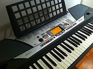
A few years ago, my old Yamaha PSR-GX76 synthesizer died a brave death. This happened due to the fact that I mistakenly connected a 24 V power supply to it instead of the put 12 V. In this mode, the synthesizer worked heroically for several minutes, after which there was a “fart”, accompanied by audiovisual special effects and a specific smell, and the synthesizer no longer turned on . Since then, he has been gathering dust in a box and waiting for his time, which finally came for him. In several articles I will tell you how the movement went from the idea to breathe new life into it to the implementation and demonstration of the results.
Autopsy
A typical synthesizer consists of several main parts: a sound generator module (usually containing a chip of the sound generator itself and a memory with samples of instruments), an audio amplifier module, and a module that scans the keyboard matrix of the synthesizer.
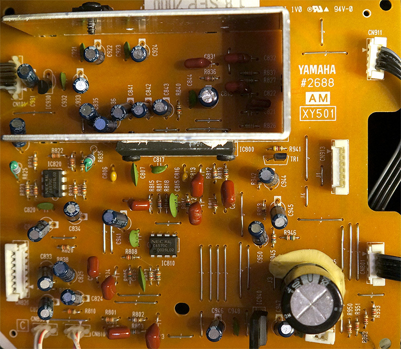
Audio amplifier module (combined with power supply)
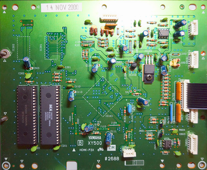
Sound generator module (memory visible, sound generator itself on the back side)
An autopsy showed that in my synthesizer the power supply voltage regulator, which was responsible for supplying voltage to the sound generator and the keyboard matrix scanner, was torn to pieces. Alas, replacing the stabilizer with a new one did not bring results. Further analysis showed that both microcircuits apparently no longer function: there are correct reset and clock signals, however, there are no signs of life on the part of the microcircuits themselves. Since these microcircuits were made specifically for the Yamaha synthesizer, it was not possible to replace them with new ones, especially since the model is already old. And then the idea came to me instead of repairing the old sound generator module, throwing it out and making my own, completely and completely customizable, with Linux and Wi-Fi.
Platform Selection - The Basics for the New Synthesizer
Lusting up on this idea, I began to select a platform on the basis of which a new synthesizer “brain” would be created. I started the search with relatively simple debug boards on the STM32, since the original idea was to implement firmware from scratch that implements sound synthesis. The selection criterion was the presence of at least several tens of megabytes of memory, an SD card slot, audio output and the ability to connect an LCD display. Then the idea came up to use something more powerful, and I remembered the Raspberry Pi lying around idle. But she did not fit in the end for several reasons: the lack of opportunity
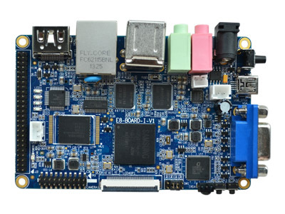
Its technical characteristics are presented in the table, the issue price is 48 US dollars:
| Dimensions | 100x65x20 mm (excluding connectors) |
| CPU | Samsung S5PV210 Cortex-A8 (1 GHz) |
| RAM | 512 MB * |
| EMMC Flash | 4 GB |
| USB ports | 4 USB 2.0 ports, 1 USB OTG port |
| Audio | Input / output up to 48 KHz, WM8960 |
| HDMI | HDMI 1.3 1080p @ 30 FPS |
| Ethernet | 100 Mbit |
| Serial port | 3 ports 3.3V, one port with standard RS232 levels |
| Clock | Real-time clock support (plus battery) |
| Memory card | Interface for SD card |
| Buttons | 2 programmable buttons |
| Camera | Special port for connecting a camcorder |
| LEDs | 4 programmable LEDs |
| IrDA | Built-in IR receiver |
| Display | 40-pin FPC for connecting LCD (support resistive and capacitive screen) |
| 50 pin connector | 17 GPIO lines, 4-channel ADC, SPI, 2 PWM, additional SD interface |
I must say, I was pleasantly struck by the volume of documentation that comes on two DVDs with a mini-computer: the disks have a complete circuit diagram, documentation for each chip used, including full documentation for the processor, a user manual (in Chinese, but everything is clear) various instructions (for example, on installing Ubuntu and even on developing with Qt). In addition, there are Linux 3.0.8 kernel source codes, Android system source code, some software from EmbedSky, GCC 4.4.3, Qt source code and much more. Two OSs are preinstalled on the board at once - Linux and Android 4.0.4, the choice of which is loaded through the U-Boot loader. Android was ruthlessly demolished by me, and all the available eMMC Flash-memory was used under simple Linux.
It is worth noting that the board was initially configured to work with a capacitive screen. In order to switch it to the resistive interface, you need to re-solder the two jumpers on the back of the board next to the LCD connector. Actually, this was the first thing I did with the board after checking its performance. Then it turned out that the Linux image wired into eMMC is also configured by default to use a capacitive sensor. He killed several hours, digging into the Qt and Tslib configs, but in the end the touch still worked as expected.
Qt version 4.5 is supplied with the board - a rather old version. I love everything new, so to work on my project, I decided to compile the latest version 5 for ARM Qt, and since I also didn’t really want to spend a lot of time on development, I decided in addition that I would write everything in Python, so I needed also the PyQt5 library. The Samsung S5PV210 processor has a built-in 3D accelerator with OpenGL ES 2.0 support, but, unfortunately, Samsung provides OpenGL drivers only for Android OS, so I couldn’t use Qt 5 with OpenGL ES support (I tried to copy the necessary DLLs from the Android image, but one of libraries was addicted to
libhardware.soand ad infinitum), so I settled on LinuxFB as a graphics output platform. There were no special problems with compiling Qt 5, as a basis I took the config for Raspberry Pi and cut out everything related to OpenGL ES. Then I compiled Python 2.7.6 using the instructions from here . There was a problem when building for PyQt5 ARM library - it turned out that the library is dependent on OpenGL headers even if Qt was built without OpenGL support. I had to patch the library to remove the dependency. The patch was published on the PyQt mailing list.. Buildability without OpenGL will also be added to upstream shortly. After building PyQt5, I successfully tested on the device the examples from the Qt distribution, ported to Python and distributed as part of PyQt.
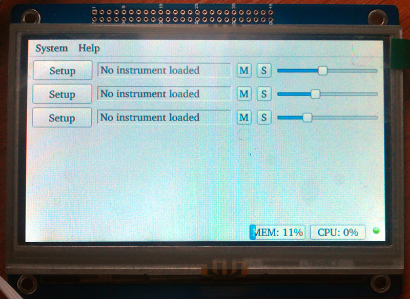
My GUI to LinuxSampler and FluidSynth written in PyQt5
This was followed by a cross-compilation LinuxSampler and its dependencies:
libaudiofile, libfftw, libgig, libsndfile, libsamplerate. An libsndfileinteresting feature was discovered, named in the library code "Ultimate sanity check" - assert that the type off_tis 8 bytes in size. In my case, this was not the case. Fortunately, simply removing this “sanity check” completely solved the problem. I wonder why it does this check at runtime but does not interrupt at the configure stage - it still won’t work, why then compile? Additionally, JACK was compiled as a sound output driver for LinuxSampler. It took patches for him
arm-timestamp.patchand atomic.patchfrom here. I also compiled with such flags for GCC, to enable extensions NEON for on ARM: -march=armv7-a -mtune=cortex-a8 -mfpu=neon -ffast-math -funsafe-math-optimizations -O3. At this stage, JACK and LinuxSampler worked for me, through which I could play MIDI files using jack-smf-player. Together with the graphical interface (see above), a Python module for working with LinuxSampler using the LSCP protocol was written, and with the help of SWIG binders for were generated
libgig, which allows you to download GIG files, and, in particular, find out what tools are inside, so that they could be selected from a list in the interface on Qt. Closer to the completion of the project, these developments, as well as all the original source code associated with the project, will be posted on GitHub for everyone. In the following article I will tell:
- How is the keyboard matrix of the synthesizer
- How I changed the burned MK keyboard scanner to ATmega, about firmware directly from the board, and how the microcontroller communicates with LinuxSampler
- How did I do a kernel with Realtime Preemption support based on stock and how were numerous problems resolved
- How did you communicate with EmbedSky Tech technical support?
- How did you reduce the latency of the sound when you press the keys of the synthesizer from a few tens to a few milliseconds
All the manipulations described in this and the next article with minor differences can also be done using other suitable ARM platforms, including the Raspberry Pi, to make your own universal synthesizer from an old MIDI keyboard. Of the advantages of the latter, one can note the presence of a more powerful hardware FPU and the ability to build Qt 5 with support for OpenGL ES 2.0.
Next article >>