Homemade Phase Laser Rangefinder
In the article I will talk about how I made a laser rangefinder and the principle of its operation. I note right away that the design is a layout, and it can not be used for practical use. It was done only to make sure that the phase range finder is realistic to assemble yourself.
Theory
It is often necessary to meet the opinion that using a laser, distance is measured only by directly measuring the time of "flight" of the laser pulse from the laser to the reflecting object and vice versa. In fact, this method (it is called pulse or time-of-flight, TOF) is used mainly in cases where the distances to the desired object are sufficiently large (> 100 m). Since the speed of light is very high, it is quite difficult to measure the time of flight of light, and therefore the distance, with high accuracy in a single laser pulse. Light travels 1 meter in about 3.3 ns, so the accuracy of measuring time should be nanosecond, although the accuracy of measuring the distance will still be tens of centimeters. To measure time intervals with such accuracy, use FPGAs and specialized microcircuits.

However, there are other laser methods for changing the distance, one of them is phase. In this method, unlike the previous one, the laser works continuously, but its radiation is amplitude-modulated by a signal of a certain frequency (usually these frequencies are less than 500 MHz). I note that the laser wavelength remains unchanged (it is in the range of 500 - 1100 nm).
The radiation reflected from the object is received by the photodetector, and its phase is compared with the phase of the reference signal from the laser. The presence of a delay in the propagation of the wave creates a phase shift, which is measured by the range finder.
The distance is determined by the formula:

Where c is the speed of light, f is the laser modulation frequency, phi is the phase shift.
This formula is valid only if the distance to the object is less than half the wavelength of the modulating signal, which is equal to / 2f.
If the modulation frequency is 10 MHz, then the measured distance can reach up to 15 meters, and when the distance changes from 0 to 15 meters, the phase difference will change from 0 to 360 degrees. A change in phase shift of 1 degree in this case corresponds to the displacement of the object by about 4 cm.
If this distance is exceeded, ambiguity arises - it is impossible to determine how many wave periods fit within the measured distance. To resolve the ambiguity, the laser modulation frequency is switched, and then the resulting system of equations is solved.
The simplest case is the use of two frequencies, at low the distance to the object is approximately determined (but the maximum distance is still limited), at high the distance is determined with the necessary accuracy - with the same accuracy of phase shift measurement, when using high frequency, the accuracy of distance measurement will be noticeably higher.
Since there are relatively simple ways to measure the phase shift with high accuracy, the accuracy of distance measurement in such rangefinders can reach up to 0.5 mm. It is the phase principle that is used in range finders that require high measurement accuracy - geodetic range finders, laser roulettes, scanning range finders mounted on robots.
However, the method also has drawbacks - the radiation power of a constantly working laser is noticeably lower than that of a pulsed laser, which does not allow the use of phase range finders for measuring large distances. In addition, phase measurement with the required accuracy can take a certain time, which limits the performance of the device.
The most important process in such a range finder is the measurement of the phase difference of the signals, which determines the accuracy of distance measurement. There are various methods for measuring the phase difference, both analog and digital. Analogs are much simpler, digital ones give greater accuracy. In this case, it is more difficult to measure the phase difference of high-frequency signals by digital methods - the time delay between the signals is measured in nanoseconds (this delay occurs as in the pulse range finder).
In order to simplify the task, heterodyne signal conversion is used - the signals from the photodetector and laser are separately mixed with a signal of close frequency, which is formed by an additional generator - a local oscillator. The frequencies of the modulating signal and the local oscillator differ by kilohertz or units of megahertz. From the received signals using the low-pass filter, the signals of the difference frequency are isolated. An example of a structural diagram of a range finder with a local oscillator. M - laser modulation signal generator, G - local oscillator.
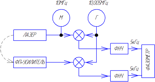
The phase difference of the signals in this conversion does not change. After that, the phase difference of the received low-frequency signals is much easier to measure by digital methods - you can easily digitize the signals with a low-speed ADC, or measure the delay between the signals (when the frequency decreases, it noticeably increases) using a counter. Both methods are quite simple to implement on the microcontroller.
There is another way to measure the phase difference - digital synchronous detection. If the frequency of the modulating signal is not very high (less than 15 MHz), then such a signal can be digitized by a high-speed ADC synchronized with the laser modulation signal. It follows from the Kotelnikov theorem that the sampling frequency should be two times higher than the laser modulation frequency. However, since a narrow-band signal is digitized (except for the modulation frequency, there are no other signals at the ADC input), the subsampling method can be used, thanks to which the sampling frequency of the ADC can be noticeably reduced to units of megahertz. It is clear that the analog part of the rangefinder is simplified.
In more detail (with all the necessary formulas) this method is considered here (in English) andhere (in Russian) .
The first article states that if the signal sampling frequency (fsp) is related to the modulation frequency (fo) by the following relation:

where p is an integer, then the phase calculation process is greatly simplified.
It is enough to take N samples of the signal X [i], after which the phase difference can be calculated using the following formulas:
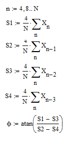
I note that both of the above methods are often used together - low-frequency signals are fed directly to the ADC, high-frequency signals are transferred to the lower frequencies due to heterodyne conversion, and also served on the ADC.
It was the second version of the phase meter, using a modulation frequency of 10 MHz that I decided to implement in my layout rangefinder.
Practice
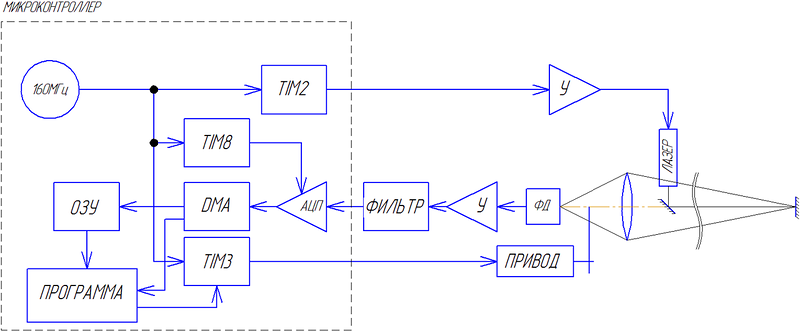
Structural diagram of my rangefinder: In fact, the entire structure consists of 3 parts - a debug board with a microcontroller, a laser signal amplifier with a laser itself, and a photodetector with an amplifier and a filter. In the above theory, it was assumed that the laser radiation is modulated by a sinusoidal signal. It is not easy to generate such a signal with a frequency of 10 MHz using a controller, therefore, in my design, I feed a 10 MHz frequency square wave to the laser. After amplification of the signal from the photodetector, excess harmonics are cut off from the received signal by an LC bandpass filter tuned to a frequency of 10 MHz, resulting in a signal that is very close to sinusoidal at the filter output. Scheme of the analog part (laser amplifier and receiving part): The circuit was taken from the laser communication project

Ronja , description in Russian . In this project, data transfer at a speed of 10Mbit is just implemented, which corresponds to the selected modulation frequency.
As can be seen from the diagram, the power amplifier for the laser is the simplest, assembled on a 74HC04 chip (contains 6 inverters). The inclusion of the chip is not entirely correct, but it works. The current through the laser is limited by resistors (also not the best solution). The 5V power supply for the amplifier is taken from the debug board.
In order for the signal from the amplifier not to be induced to the rest of the circuit, the amplifier housing is made of metal, all wires are shielded.
The laser itself (red) is taken from a DVD writer, its power can be set high enough, and it is guaranteed to work at a frequency of 10 MHz.
The receiver consists of a photodiode and an amplifier assembled on a field effect transistor and a high-speed amplifier chip. Since the illumination of the photodiode decreases significantly with increasing distance, the gain should be quite large (in this scheme it is approximately equal to 4000). In addition, with increasing frequency, the signal at the output of the photodiode noticeably decreases (its capacitance affects). I note that the amplifier in this design is the most important and most moody part. As it turned out, its gain is clearly not enough. Initially, I assumed that the gain can be changed (in order to attenuate the signal when it is too large), the circuit used allows you to do this by changing the voltage at the second gate of the transistor. However, it turned out that when the gain changes, the phase shift introduced by the amplifier changes sufficiently
The receiver requires a voltage of 12V for operation, so you have to use a separate power supply to power it.
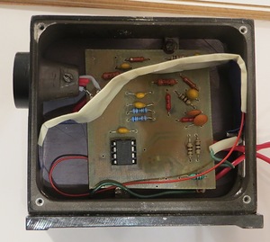
The amplifier is very sensitive to external interference, so it must also be shielded. I took the finished case from a non-working optical sensor, and placed the amplifier in it (white strip - foil for additional screening of the photodiode): I note that aiming the signal from the laser to the receiver pretty much degrades the accuracy of measuring the phase difference, so you need to control that such a tip was absent. LC filter used in rangefinder - taken from receiver
. Since the filter cuts off the constant component of the signal, and the ADC does not perceive negative signals, it has to be added using the resistor divider R15, R16. The DC voltage supplied to the divider is taken from the debug board (VCC).
Debug board - STM32F4-DISCOVERY. She chose it because to generate two sufficiently different frequencies, a generator of a sufficiently high frequency is needed (PLL STM32F4 can give frequencies above 100 MHz).
In the formula relating the modulation and sampling frequencies, I took the coefficient "p" equal to 6, so that at a modulation frequency of 10 MHz, the sampling frequency should be 1.6 MHz.
To generate a frequency of 10 MHz, a TIM2 timer is used, operating in the mode of generating a PWM signal. At a system frequency of 160 MHz, its period is 16 ticks.
The ADC receives start requests from the TIM2 timer. To form a frequency of 1.6 MHz, its period is 100 ticks. All data from the ADC using DMA is stored in an array whose size should be equal to two in the N degree. Both timers, ADCs and DMAs start once upon power-up and are no longer turned off. Thus, since the timers are clocked from one source, and four data samples correspond to one period of the measured signal, it turns out that an integer number of signal periods always fall into the array.
Since stopping DMA is not advisable (this simplifies data capture control), an interrupt is generated when the first half of the array is full. Having discovered that half of the array is full, the controller copies its contents to another array (in order to simplify the program, the second half of the main array is not used). After that, the received data is processed - the average amplitude and phase of the signal are calculated, the phase shift is recalculated into the distance.
The obtained values are displayed on the LCD indicator from the cash register, also connected to the debug board.
The range finder must know where the reference is located. To calibrate it, when turned on, an object is installed at a “zero” distance from the range finder, after which you need to press a button on the debug board, and the measured range value is written to memory, after which this value will be subtracted from the range measured by the range finder.
As I noted above, it was not possible to implement automatic gain control. In this case, a change in the amplitude of the received signal leads to a change in phase shifts in the amplifier, and therefore to additional errors.
Therefore, I had to adjust the illumination of the photodiode using a mechanical damper rotated by a servo-driver - if the illumination is too high, the damper blocks the luminous flux. The PWM signal for controlling the drive is generated by the TIM3 timer.
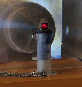
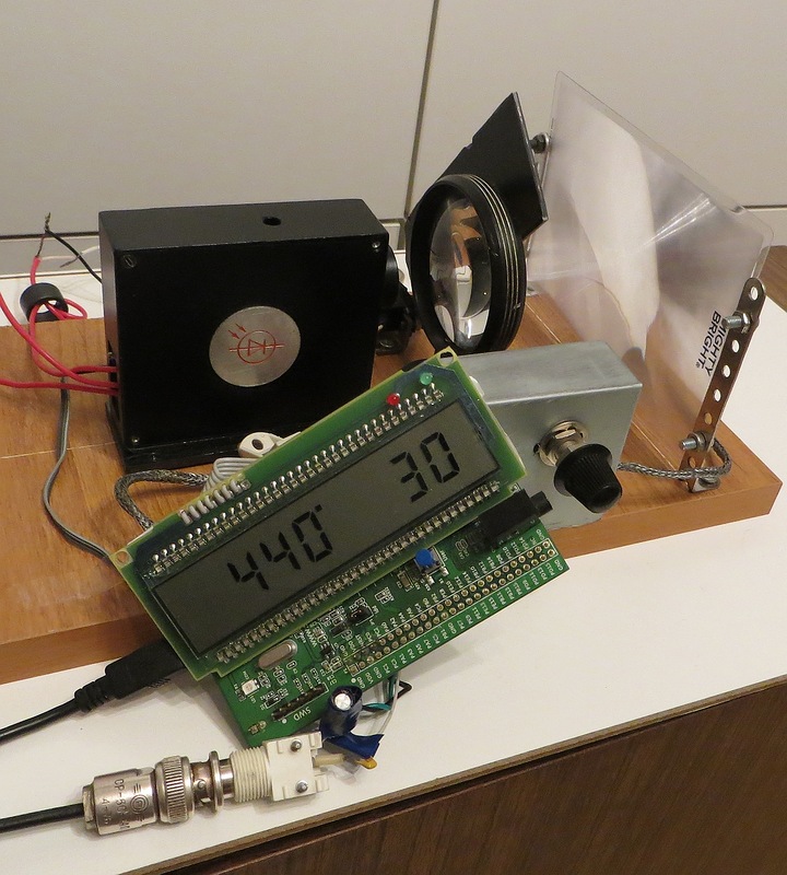
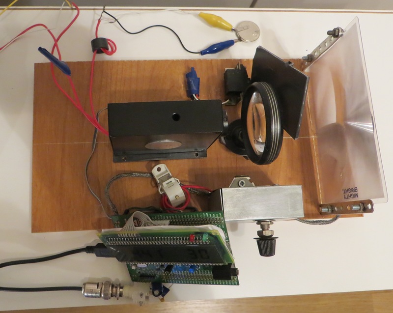
About optics. Without it, a rangefinder is impossible. Its design is clearly visible in the photographs below. The laser is located inside a plastic tube mounted vertically. A small sleeve with a mirror prism is inserted into it. The sleeve can be rotated, raised and lowered, thus moving the laser beam. Since I knew that there wasn’t enough amplification, I used a large Fresnel lens to receive the signal.
Since the laser, the lens and the photodiode are aligned, the laser closes its own beam from the photodiode at close distances. To compensate for this effect, I installed a second lens (a magnifying glass with a frame), although the effect is not completely eliminated, so the maximum signal is observed at a distance of about 50-70 cm from the laser.
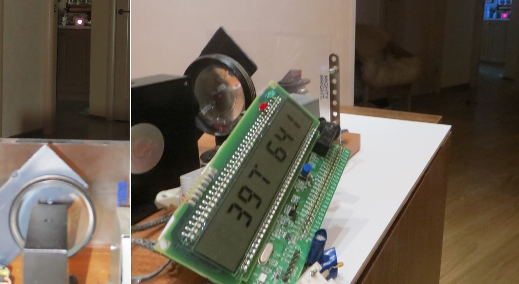
And here are photos of the resulting design:
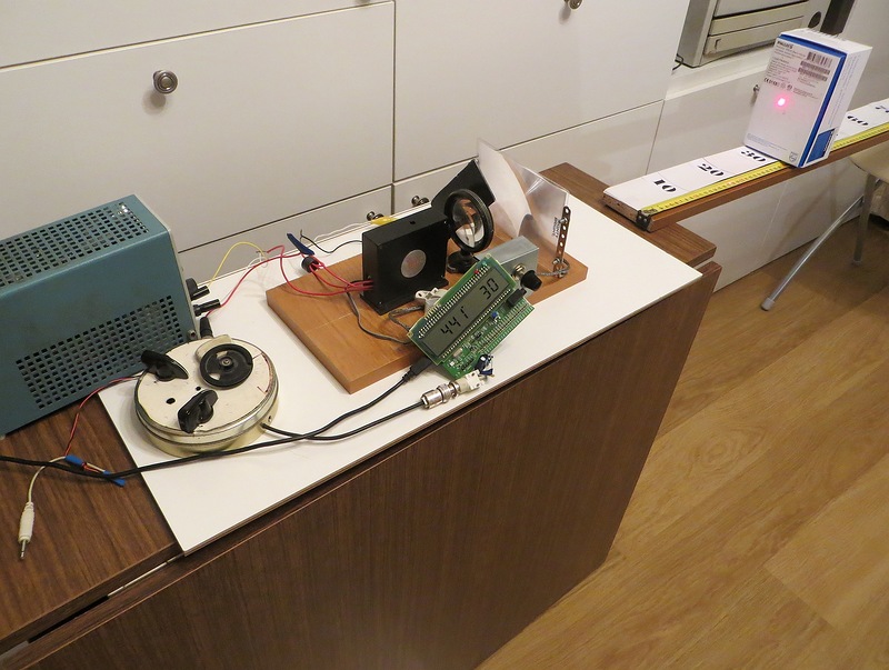
On the indicator, the first number is the amplitude in ADC units, the second number is the distance in centimeters from the edge of the board. Rangefinder operation video:
The operating range of the resulting rangefinder came out quite small: 1.5-2 m, depending on the reflection coefficient of the object.
In order to increase the range, you can use a special reflector, which will need to direct the laser beam.
For experiments, I made a lens reflector, consisting of a lens with matte paper in focus. This design reflects the light at the same point from where it was released, however, the diameter of the beam increases.
Photo of the reflector:

Using the reflector: As you can see, the distance to the reflector is 6.4 meters (in reality it was about 6.3). In this case, the signal increases so much that it has to be weakened by directing the laser beam at the edge of the reflector.
The accuracy of the resulting range finder is 1-2 centimeters, which corresponds to the accuracy of measuring the phase shift - 0.2-0.5 degrees. At the same time, in order to achieve such accuracy, the data have to be averaged too long - it takes 0.5 s for one measurement. Perhaps this is due to the use of PLL to generate signals - it has a fairly large jitter. Although I believe that for a home-made layout, the analog part of which is made rather clumsily, in which there are quite long wires, even such accuracy is pretty good.
I note that I could not find on the Internet any existing project of a phase range finder (even with a design diagram), which was the reason for writing this article.
Controller program: link