Architecture and Programming RCA Studio II
“Finally, we came to the instruction!”
/ From the CDP1802 microprocessor article /
In the early 1970s, simple electronic games like Pong were very popular in the USA (in the USSR, their counterparts went on sale in 5-10 years). As a rule, such games did not have a microprocessor and no memory in the modern understanding of these words, but were built on rigid logic. Accordingly, the replacement cartridges did not have much sense, and where they were - were just a bunch of jumpers, including the desired game.
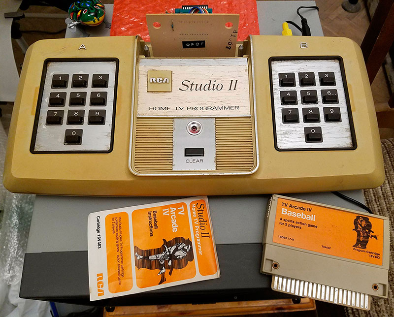
In 1977, two consoles were released almost simultaneously: Fairchild Channel F and RCA Studio II. These were the first game consoles in the form of full-fledged computers - with a microprocessor and programs on replaceable cartridges. The RCA Studio II prefix, which we are talking about, is a development not only of RCA , but of a particular person - Joseph A. Weisbecker (like all COSMAC architecture) .
The first such device - System 00 , also known as COSMAC FRED (1971) was a prototype and was not mass-produced.
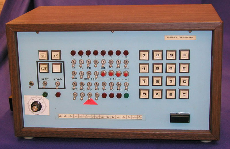
The processor in it was implemented on the usual logic (in FRED2 - on two chips under the name CDP1801 R and U, which appeared in 1973). RAM was in the region of 256 bytes - 4 kb, in addition to FRED2 there was a built-in tape recorder.
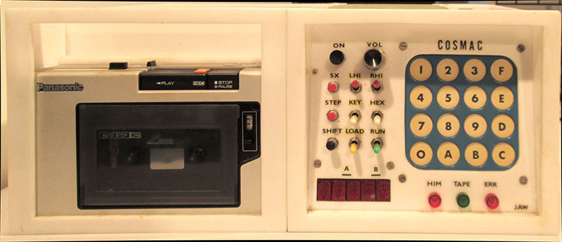
The first commercial implementation of the COSMAC architecture was the COSMAC ELF device . In 1976, ELF was positioned as a computer for radio amateurs ( published in Popular Electronics magazinea series of articles) and was a small board with toggle switches, indicators, a microprocessor CDP1802 (the same 1801, but in one chip) and 256 bytes of RAM. For it, there were additional expansion cards that allowed displaying graphics on a monitor (using a CDP1861 chip), an external keyboard and a tape recorder were connected. On the basis of ELF with extensions appeared ELF II and VIP. In the COSMACs ROM, there was a virtual machine called CHIP-8, sharpened for primitive games (commands for outputting and moving software sprites, generating random numbers, etc.) There were other primitive computers and terminals based on this architecture.

All these devices were direct predecessors of RCA Studio II and have an extremely close both hardware and software architecture.
RCA Studio II was released in 1977 and was then sold at a price of $ 150 ($ 600 for current money). As is often the case, the first on the market is not necessarily the most successful. In 2008, PC World magazine recognized this console as the worst gaming console of all time (which is not far from the truth). A black and white image from small squares, no joysticks (two fields of 10 buttons instead) and a dozen games - to put it mildly pleased customers.
In addition, all games (both built-in and sold on cartridges) were written in the pseudocode of the ST2 virtual machine (the same idea as with CHIP-8 in COSMACs), which is why they are very slow.
RCA managed to release about 64 thousand units of RCA Studio II, not counting the clones that appeared later (Toshiba Visicom, Conic M-1200, etc.) With the advent of Atari VCS , the outdated RCA Studio II and Fairchild Channel F instantly dropped out of the fight.
CPU
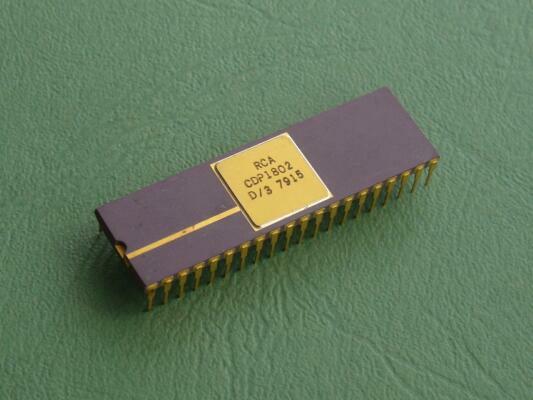
As a chip maker, RCA chose its own product as a set-top box processor - the RCA CDP1802 microprocessor , operating at 1.78 MHz and manufactured using CMOS technology.
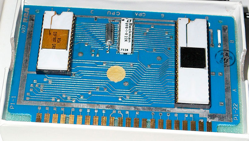
Its predecessor was the CDP1801 two-chip processor (fully compatible with 1802):
CDP1802 is known for its radiation-resistant version (silicon on sapphire), in which it was used, for example, at the Galileo interplanetary station , which flew to Jupiter in the 1990s (there were 6 such processors), as well as in MAGSAT .
The processor has a rather tricky register usage pattern. It has one 8-bit battery D and sixteen 16-bit registers - R0..RF (R0-R15), each of which can become a command pointer, depending on the contents of the 4-bit register P (pointing to one of R), changeable team sep rn. In other words - there is no single PC in the processor!
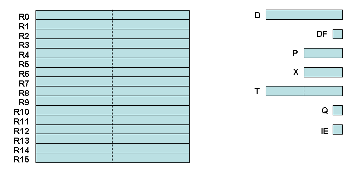
In addition, any of R0 ... R15 can become an index (address). The choice is determined based on the value in the 4-bit register X (modified by the command SEX Rn), after which the selected R is considered to be index for some commands.
R0 is always used as an address register for DMA. Inside the interrupt, the instruction counter is R1.
There is an 8-bit T register, which is used to automatically save the X and P registers in it when an interrupt occurs. Interrupts are enabled by setting the Interrupt Enable flag (IE) via the RET or DIS commands.
The 4-bit registers I and N contain the instruction currently executed by the processor.
There is a register of flags - DF. More precisely, one flag, since it is single-bit and contains only the carry flag.
In addition, the processor has a one-bit Q output port, the state of which is changed by the SEQ and REQ commands.
As in many processors of that generation, the stack in the usual sense is absent here (there are no PUSH, POP commands, or a stack pointer) and, if necessary, is implemented by the existing instructions.
There are no traditional instructions for calling subroutines either. The transition to the subroutine is carried out using the instruction SEP Rn which, I recall, makes the specified Rn register the command counter. For the return, the same SEP instruction is used, but with the register which was the instruction counter before the call. Or (in a more universal, but slower version) is used MARK and RET.
In addition to traditional conditional and unconditional jumps (by the way - they are all absolute), there are several SKIP instructions that, if the condition is met, skip the instruction following the SKIP (two bytes). Provided and unconditional SKIP.
The 1802 processor is often mentioned as one of the first RISC processors. However, in the same context, it is mentioned, say, 6502, as well as some others. It is certain that the architecture is not quite ordinary and, from the point of view of programming, evokes mixed feelings. On the one hand, there are already sixteen 16-bit registers. On the other hand, their content itself can only be reduced and increased by one. For example, putting a constant in Rn looks like this:
ldi$01         ; const -> D
    plo     r6      ; D -> R6.0
    ldi $02         ; const -> D
    phi     r6      ; D -> R6.1
Therefore, the lion's share of the code is moving the bytes back and forth.
From transitions by condition there is, in practice, only a transition by zero (only the situation when 0 is in battery D is considered) and the transfer flag. Typical cycles are as follows:
loop:
    ...
    dec     r7      ; R7--
    glo     r7      ; R7 -> D
    bnz     looploop:
    ...
    adi     2       ; D = D + const
    xri     $07     ; compare using XOR.  (D == const) -> D
    bnz     loop
All arithmetic and logical instructions work only with battery D.
In addition to the one-bit port controlled by SEQ / REQ, there is also a four-bit one that is controlled by OUT / INP commands. Unfortunately, it is not used in RCA Studio II.
MEMORY
Available: 2 kB of ROM (BIOS + five built-in games) 512 bytes of RAM (half allocated for video)
Memory card
000-2FF ROM     RCA System ROM : Виртуальная машина SP2
300-3FF ROM RCA System ROM : BIOS
400-7FF ROM Встроенные игры (доступны только если нет картриджа)
400-7FF ROM Картридж (когда вставлен) 1024б
800-8FF RAM можно использовать (256 байт)
900-9FF RAM Экран (256 байт)
A00-BFF ROM Картридж (обычно нет)
C00-DFF --- Тоже самое, что 800-9FF
E00-FFF ROM Картридж (обычно нет )
It is necessary to specifically stipulate that for games and programs on cartridges only part of the BIOS is available - the one that contains SP2 (unnecessary, by and large), images of digits from 0 to 9 and the standard interrupt handler for video.
VIDEO
For graphics, use the RCA chip CDP1861 - the so-called "Pixie".
The standard RCA Studio II has only antenna output (RF), but people convert it into composite to make the quality better (I almost wrote - “for better color rendering” :))
Technically, the video controller provides the maximum resolution of 64x128 in two colors (black and white). ). However, this requires 1024 bytes of video memory, and in Studio II the total amount of RAM is 512 bytes. Therefore, the resolution is 64x32 (which requires 256 bytes). The horizontal resolution (64) is fixed. In one line of 64 pixels, 8 bytes is always displayed, and this happens within 14 processor cycles.
To display the memory ($ 900- $ 9ff) on the screen, use the BIOS interrupt handler. The interrupt is initiated by the video controller and occurs 60 times per second (NTSC). The BIOS handler performs all the necessary operations — the executable program only needs to change the video memory in which each bit directly corresponds to a black or white dot (from left to right, top to bottom).
However, nothing prevents you from writing your handler. The simplest case is the resolution of 64x128, since it is natural for the video controller. For it, in the handler, it is enough to only write the address of the video memory to R0 (where the data will be taken for display on the screen) and the bytes will start to be displayed via DMA themselves filling the frame. The vertical resolutions other than 128 are more complicated. There you will have to enter delays and duplicate data, changing R0 (see description of cdp1861 and BIOS sources).
In principle, you can even make a variable vertical resolution, not output anything to a part of the screen, and also specify ROM as a video memory, not RAM (or partially ROM, and partially RAM). You can also implement vertical scrolling by changing the initial address from which data starts to be issued to the controller.
Note that at the INT output of the video controller, the unit appears two lines before the beam reaches the visible area. Therefore, the interrupt handler usually starts with a delay that allows you to start mapping memory on time.
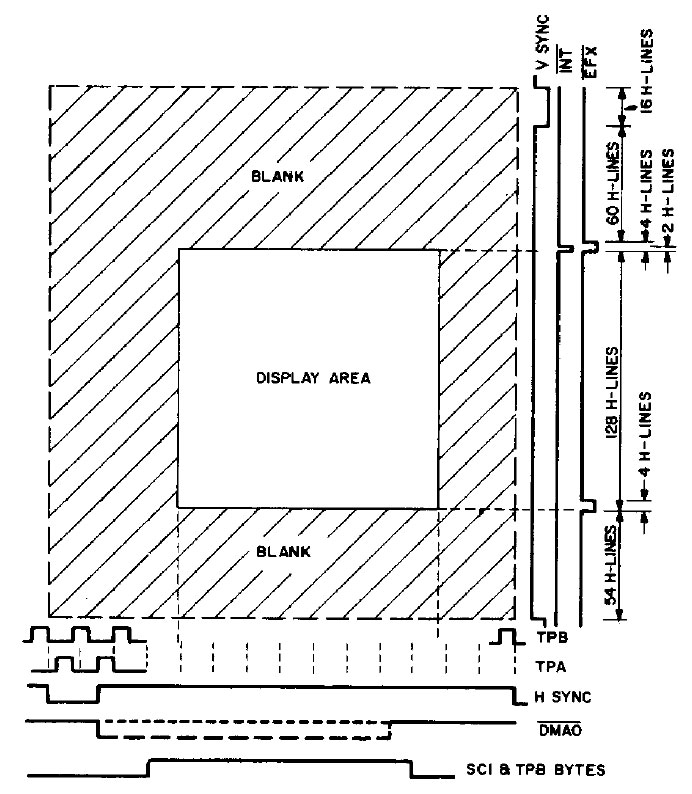
The video controller also has an EFX output, on which 0 appears over 4 lines before the beam appears in the visible area and then throughout the 4 last lines of this area. The EFX output is connected to the EF1 of the processor and its status can be checked with command B1 (BN1).
Typical waiting for the return path on the frame is implemented as follows:
...
delay:
    bn1     delay    ; waitfor EFX in video chip
...
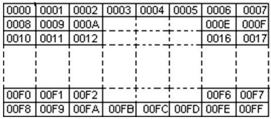
As already noted above, in the ROM there are no images of letters and characters. However, the numbers are still there (after all, in embedded games, you need to somehow show the points and player number). However, even here they managed to save:

As you can see, the numbers are molded so that the remaining ones are made from several adjacent ones.
SOUND
Let's just say - there is sound. But not more. The NE555 is attached to a single single-bit output port of the CDP1802 with a harness and then it is all connected to the speaker built into the console. When a unit is fed to the RST NE555 input (command of the SEQ processor), it starts squeaking at 625 Hz. When zero (command REQ) - squeaks. Actually that's all. However, there is still a capacitor due to which, at the beginning of a squeak, the frequency within 0.4 seconds smoothly decreases twice (i.e. some additional screeching is obtained).
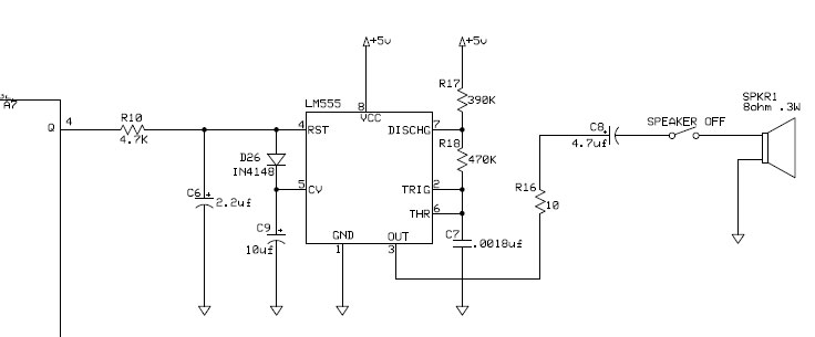
In the standard BIOS interrupt handler, in addition to the part responsible for the video, there is a piece that checks the contents of a specific memory cell and, if there is not zero, turns on the squeak and starts cyclically decreasing the contents of the $ 08CD cell (when zero is reached, the squeak off). Thus, you can not bother with self-recording in the port, but simply set the duration of the squeak and it will occur in the background, without stopping the program:
    ldi     $8cd & $ff
    plo     rf
    ldi     250     ; длительность писка
    str     rf
    ...
The same can be done manually (after turning off the interrupts):
; выключаем прерывания
    sex r3      ; set X to R3
    dis           ; return X to R5, P to R3, 0-IE, R3=R3+1
    db  53h    ; forces X=5 P=3 - which is no change
; включаем писк
    seq
; пустой цикл
    ldi     250     ; delay
    plo     r6
delay:
    dec     r6
    glo     r6
    bnz     delay
; выключаем писк
    req
; включаем прерывания обратно
    sex r3      ; set X to R3
    ret           ; return X to R5, P to R3, 1-IE, R3=R3+1
    db  53h    ; forces X=5 P=3 - which is no change
PROGRAMS
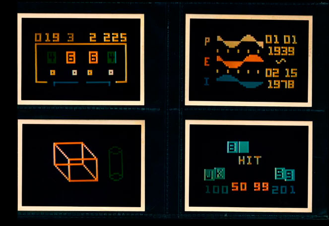
In the 1970s, a little more than a dozen games and several other programs were written (mostly by RCA itself). Almost all of them were written not in assembler, but in pseudocode - a special interpreter-virtual machine ST2 is in the ROM of the set-top box. It is difficult to say exactly what motivated this decision. Most likely, the idea was to save memory - the games really turn out to be substantially less in volume. In general, ST2 ears grow from a similar VM called CHIP-8 , used in COSMACs. Although both VMs are incompatible with each other, already in the 2000s a CHIP-8 interpreter for RCA Studio II was written. Given the extreme similarity of the architectures, it is not surprising that, as the interpreter's author writes, games with COSMACs that did not require a lot of memory were launched without any problems on RCA Studio II.
Alas, the VM on such an architecture works very slowly, which leaves an indelible imprint on the games themselves. Later, in 2013, Paul Robson wrote about a dozen more games - already in assembler and distributed them with source code.
DEVELOPMENT
Initially, according to witnesses, the development for RCA Studio II was carried out even without an assembler - on COSMAC ELF and FRED2.
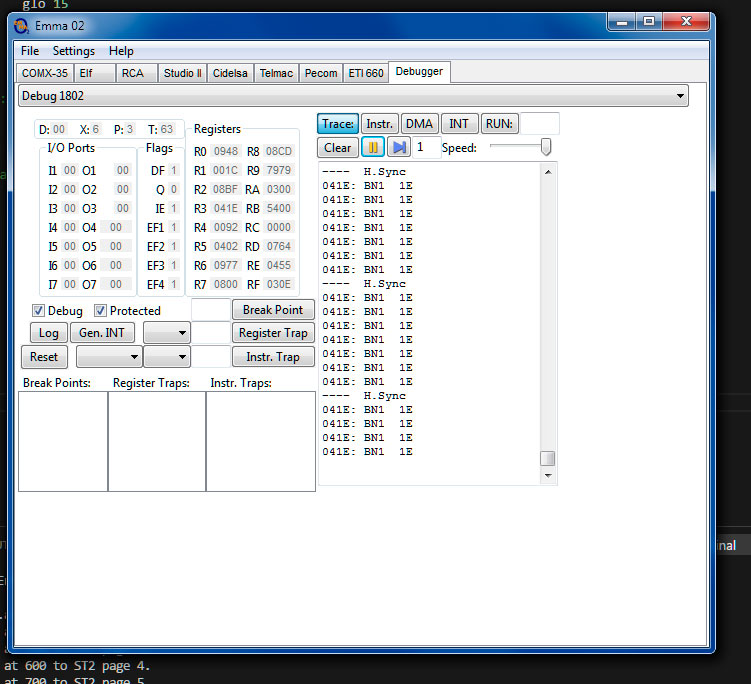
At present, there is no need to suffer this way. There is a decent emulator under Windows - Emma , with a good debugger (by the way, it emulates not only RCA Studio II, but all COSMACs as well).
As an assembler, I first tried to use a18 a cross-assembler, but for several reasons I ended up with asmx , which also has Python scripts to generate a finished image of the cartridge (it has the .st2 extension).
A brief introduction to the 1802 assembler can be found here . The simplest test.asm for RCA Studio II with an infinite loop will look like this:
        .include"1802.inc"
        .org    400h
        .db     4,2 ; SYS $402
start:
       br  start   ; some code
       .end
Pay attention to the instruction ".db 4,2". This is the address of the first instruction to be executed, i.e. ".db> (start), <(start)".
Implementing a simple loop:
        ldi     50      ; загружаем в регистр D чисто итераций
        plo     r6      ; помещаем содержимое регистра D в младший байт регистра r6
loop:
        dec     r6      ; r6 = r6 -1
        glo     r6      ; помещаем младщий байт регистра r6 в регистр D
        bnz     loop    ; переход на метку loop если в регистре D не ноль
Using SKIP instructions:
; q = 0 на протяжении $FF00 итераций, и q=1 на протяжении $FF итераций
loop:
    ghi     r1      ; hi(r1) -> D
    lsz               ; пропустить следующие 2 байта, если в D ноль (т.е. перейти к seq)
    req              ; 0 -> Q
    skp              ; пропустить следующий 1 байт в любом случае (т.е. перейти к inc r1)
    seq              ; 1 -> Q
    inc     r1       ; r1 = r1 + 1
    br      loop    ; повторить
...
To work out in pure assembler CDP1802, convenient to use online assembler emulator asm80 . The extension of the source file to be created must be .a18.
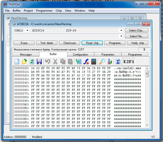
To run the finished application on real hardware, there is a RCA Studio II 40th Anniversary Multicart cartridge in nature . I did not have it, but tnt23 redid one of the available cartridges with the game under the EEPROM AT28C16 chip (2k x 8) installed in the socket.
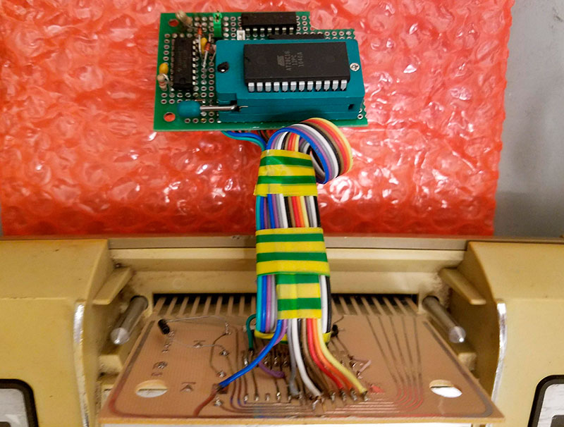
So, to run on a piece of iron, I inserted the chip into the programmer each time, flashed it, rearranged it into a converted cartridge, turned on the set-top box. And so every time.
INTRO "NO SHADERS"
In order to master the platform, I wrote 256 bytes of intro (presented at Chaos Constructions'2018 in the Tiny intro competition ).
Unlike, say, from Vectrex , where you can get a spectacular picture even by simply drawing a curve or from Videopac , where the ROM already has a set of images of little men, here we have a sad situation - an ordinary, familiar, raster graphics, but black and white and the resolution is nowhere below (64x32). In the ROM, there is not that pictures, but even characters. Sound - and that is limited by the frequency of 625 Hz.
Thus, the music was canceled, all types of plasma, lights and in general everything that involves non-square contours. The text in any form was also canceled - there would not be enough space for letters.
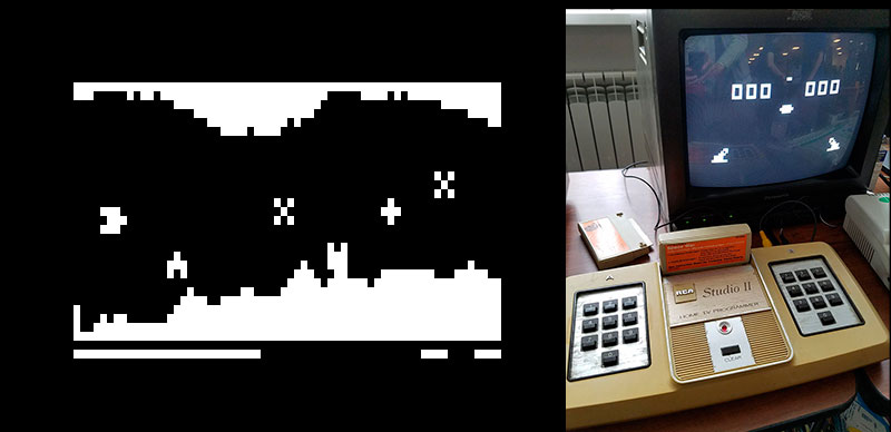
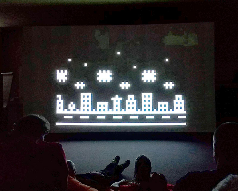
As a result, it was decided to a) scroll b) something repeating c) at different speeds. It turned out like this:
As mentioned above, there is no hardware scrolling in the video controller. However, low resolution and black-and-white not only have minuses, but also pluses - less bytes are rewritten.
I scrolled line by line, using the shlc command (left shift with transfer) - when executed in a loop, it turns out that the leftmost bit from the next byte is shifted to the left and does not disappear, but placed in the carry flag (DF). Accordingly, the next shlc in the loop picks it up and places it in the byte to the left. It turns out a simple scrolling of the entire string, which will scroll eight times in a cycle (since it is convenient to take patterns of clouds and houses byte-by-byte)
...
scrollret:
    sep r3          ; return from subroutine
; НАЧАЛО ПОДПРОГРАММЫ
scroll:
; set lines counter
    ldi LINES       ; const -> D
    plo     r10      ; D -> Rn.0
nextline:
; set bytes counter
    ldi BYTES_PER_LINE     ; const -> D
    plo     r7          ; D -> Rn.0
; set carry to scroll
    glo r12            ; Rn -> D
    shr                  ; get one bit to set carry
    plo     r12        ; D -> Rn.0 (save shifted byte)
nextbyte:
    ldx                  ; Rx -> D
    shlc                 ; D = D << 1 (carry -> DF)
    stxd                ; D -> M(Rx), Rx--
    dec r7             ; Rn--
    glo r7              ; Rn -> D
    bnz nextbyte
    dec r10            ; Rn--
    glo r10             ; Rn -> D
    bnz nextline      ; one line (8 bytes) scrolled, let's scroll next
    br  scrollret
...
Note that the entry point to the subroutine is on the scroll label, and to return, it is not just sep r3 that is executed, but first the br scrollret and already from there sep r3.
This is done in order to leave r14 (which is the instruction counter inside the subroutine) in the correct state, then the subroutine can be called again and again (using sep r14).
Of course, no variables are saved here when calls are made - all registers-variables are global.
The subroutine scroll is called twice in the general cycle - every second time for houses and every fourth time for clouds (they scroll slower). The overall cycle is synchronized in the reverse direction of the beam (the road, at home, the clouds - they have time to draw, the stars are static). In the case of the road, only one line scrolls - the edges of the road are simply drawn with lines.
I, for the sake of interest, tried to scroll the entire screen - the time does not fit in the reverse direction of the beam.
Houses are given by patterns:
...
house1:
    .db %00000000
    .db %11111111
    .db %10101010
    .db %11111111
    .db %10101010
    .db %11111111
    .db %00000000
    .db 1
house2:
    .db %00000000
    .db %00011111
    .db %01110101
    .db %01011111
    .db %01110101
    .db %00011111
    .db %00000000
    .db 1
...
and a sign with a link to each:
...
commands:
    .dbhouse5.dbhouse2.dbhouse1.dbhouse3
...
In the loop, this label is sequentially iterated.
Unlike houses, both clouds, for simplicity, are one pattern that simply cycles.
A number of bytes could be won due to the output of clouds on the same principle as the houses, as well as due to the program intervals between the patterns (now they are just repeated zeros in the data).
The problem, however, is that the part of the registers is used by the interrupt handler - R0, R1, R2, R8, R9, R11 cannot be changed. And storing variables in memory is a lot of extra bytes on their writing and reading (not to mention the ticks).
Ideally, probably, you should scroll in the interrupt handler. However, for this you would have to write your handler instead of the standard one. It would be more correct (and, incidentally, could release a couple of R registers), but, most likely, in the end, everything would not fit into 256 bytes.
As for the stars, they are static, however, to draw a few points that look randomly located, suddenly turned out to be not so simple:
...
loop:
    ldn r4                  ; M[Rn] -> D
    ani %00000010     ; D AND const -> D
    bdf skip               ; jump if carry
    ldi 0                    ; const -> D
skip:
    stxd                    ; D -> M(Rx), Rx--
    glo r4                 ; Rn -> D
    adi 47                 ; D + const -> D
    plo r4                 ; Rn -> D
    glo     r15           ; Rn -> D
    bnz     loop
...
Here in the cycle, data is taken from the BIOS, which is thinned out and extra bits are masked. Mask (for ani) and step (for adi) are selected manually.
As for the sound, the impossibility to change the frequency is simply imitated by the “beeps” of the car.
By the way, I suppose that this intra is the first demo screening work for RCA Studio II :)
EPILOGUE
After Studio II, RCA released several copies of RCA Studio III . Differences in two things - the color appeared (the resolution did not change) and the sound became better (you can give out not one, but 255 different frequencies).
Interestingly, both machines are compatible with each other in both directions, including through the use of the same intermediate code with the interpreter.
It is also known that there were plans for RCA Studio IV. There, the resolution should have increased to 64x128 and even a new pseudo-code interpreter was already written.
As for the CDP1802, this microprocessor continues to be produced - first it was made by Hughes, then Intersil (Renesas).
Those who want to learn more about this unique branch of the history of the development of computing technology, I recommend to google the words " COSMAC" and "CDP1802 ".