The history of the development of a well protection system: through thorns to intelligent sensors
 Today I want to tell you about our experience in developing systems for the protection of cable viewing wells, which are managed by telecom operators. For 9 years we have been dealing with this complex topic. How many technical solutions have been tested, how many “copies have been broken” during this time, and for the following reasons:
 Firstly, the aggressive environment of the well (temperature extremes, flooding) is detrimental to any electronics;
Secondly , installation in a well is not convenient - it requires various stages of sealing and thoughtful recommendations from the manufacturer.
Add to this a low profitability (the technical solution must be inexpensive, because there are at least hundreds of wells in each branch) and the need to bear responsibility for the result, which is hardly predictable under such conditions - here is a set of reasons why only a few manufacturers are engaged in this area the world.
We are "brought" to this topic by the "wind of history." It so happened historically that the Censor-Technotronics hardware and software complex began with the topic of monitoring line-cable structures , of which well protection is a part. Therefore, we were involved in this issue, and now our interest is determined to a greater extent by responsibility to numerous users and professional pride than by the level of profitability of the product.
For reference: why is it necessary to protect cable wells?
For those who are far from this topic, I want to clarify that cable sewer wells are part of the linear-cable structures operated by the telecom operator since Soviet times. Through cable wells, access to the main cable is provided, which is a welcome prey for homeless people and other attackers. In addition, the cast iron lid itself is of interest to scrap seekers. And, finally, the last danger, which eliminates the installation of wells for signaling, is unauthorized laying of cables by competing operators that do not have their own infrastructure (cable ducts).
The first pancake is lumpy
The first solution that existed on the market at the beginning of the 2000s and was made by us was the control of wells based on the USI96K controller. During operation, it turned out that it does not fully meet either the reliability criteria (devices placed in wells often failed due to humidity and flooding), or the criteria for ease of installation. The fact is that on one pair of wires (and there were six inputs for such pairs on one device) there could be only 16 wells, so additional wires had to be laid when the route had a branched topology, and when there were more than 16 wells on one route, and in most cases, this is exactly so.
2007 - Matrix method for monitoring wells
In 2007, in spite of previous experience, we developed a unique technology - a matrix method for monitoring wells. The matrix method did not require the installation of active electronics in the wells and therefore was as reliable as possible - there simply was nothing to break. The CCI cable (or another) was used as the communication line in this system, which connected the opening sensor to the MAKS LKS controller located on the telephone exchange. In the matrix method, the address identifier of the opened well was not active electronics, but a certain pair of wires connected in a special way. I will not describe the essence of the technology here - it is not the easiest to understand and requires a separate discussion, however, those who wish to understand can follow the link. I can only say that with the obvious advantages of popularity in Russia, the method did not gain. Among the reasons, customers called the difficulty in understanding and significant cable consumption. But in Kazakhstan, the matrix method has gained recognition - Kazakhtelecom controls its wells in this way and continues to retrofit the tracks.
2009-2011 - development of Intelligent Reed Sensors (IHD)
So, since no solution was found that was suitable for everyone, we continued the search. And in 2009, a new element base appeared in the world (a microprocessor with the necessary characteristics), which made it possible to develop an Intelligent Reed Switch (IHD) . IHDs are magnetic contact detectors with a built-in electronic board that constantly transmit data about their status to the MAKS LKS or MiniMAKS controllerplaced usually on the telephone exchange. IHDs are distinguished by their speed (tamper fixation time - 0.1 sec., Data delivery time to the Dispatch Center - 1 sec.), Resistance to interference, lightning pickups, internal short circuits. In addition, the failure of one or more sensors of the IHD does not affect the operation of the others. But the main advantage of the IGD-based system was the ease of installation. The technology allows targeted monitoring of at least 64 wells on one pair of wires and is therefore ideally suited for any routes, even with a complex branched topology.

Fig. 1. The scheme of the security system based on intelligent reed sensors (IHD)
Thus, everything was wonderful with both the electronic filling and the installation technology, there was only one question - reliable sealing of the electronics. Since the sensor was originally made on the basis of the well-known tamper-evident type sensor IO102-20, we assigned the installation of these sensors to the body and sealing of our electronic circuit boards. The second stage of sealing, of course, was to be performed by the user during installation - it was necessary to seal the junction of the sensor wires and the loop. We were very pleased with the development, however, during the first flood, the sensors began to fail. As it turned out on the basis of the trips of our experts, some of the sensors or the junction of the sensor’s wire with the track could not withstand the multi-day stay in water in a flooded well. The tracks were especially problematic, mounted without proper adherence to the installation rules developed for this system. Routes mounted in accordance with all the rules, in general, worked properly.

Photo 1. Intelligent reed switch of the IHD in the old building. year 2009.
However, blaming the flaws of installation is not a solution. Our developers understood that it was necessary to radically revise the design of the sensor and the wire in terms of sealing and make it such as to minimize the impact of the “installation quality” factor on the system’s performance.
We also understood that a reliable sealing solution must be sought in a completely different field - not from manufacturers of sensors, which simply are not required to have groundwork on this topic. First of all, we thought about manufacturers of products for the oil and gas industry or the defense industry. And we are lucky! We found a partner whose own developments in sealing were suitable for solving our problems as well as possible. A small remark: we do not want to disclose the name of the organization of our partner to make it difficult for competitors to copy our technical solutions.
Our then still future partner enthusiastically responded to the proposal to resolve the issue of sealing our "well" sensor and the cable connected to it. And the work began to boil: numerous approvals, business trips, tests, further strengthening of the structure, tests again and again improvements. And finally, before us is the IGD, sealed so that not a single “paranoid” could have faulted, because it was sealed by the “paranoid” themselves, constantly asking questions from the category of “what if force majeure and ....” happen. Below are the results of our joint efforts.
Monolithic polyurethane "cocoon"

Photo 2, fig. 2. The modern intelligent reed switch of the IHD sensor.
The device body and the sensor cable connected to the track are a single unit made of polyurethane. Polyurethane is a synthetic polymer material, which is called "material with unlimited possibilities", because it:
- Firstly, it is completely tight and is universally used for waterproofing.
- Secondly , the operating temperatures of polyurethane products are in the range from minus 70 to 100 ° C, while the elasticity practically does not change.
- Thirdly , polyurethane has high dielectric properties, which is very important for the isolation of electronics.
- Fourth, polyurethane has high mechanical strength, because it is not for nothing that it makes parts and components of machines subjected to high dynamic loads, but there is nothing to say about the production of polyurethane soles and heels.
Sensor cable has 4 degrees of protection
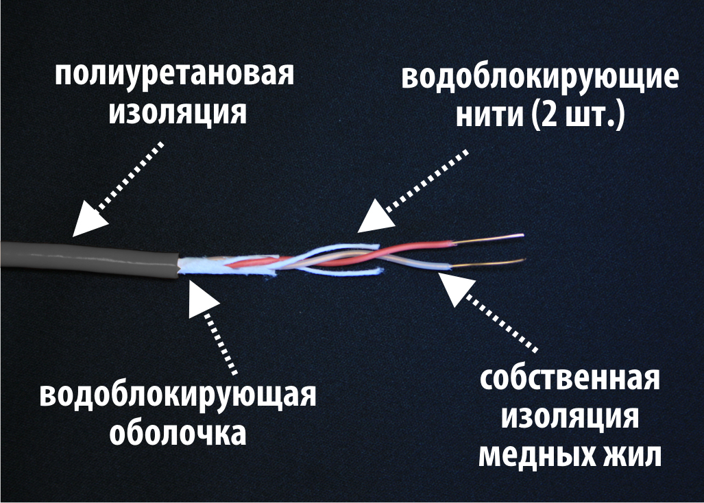
Fig. 3. Cable insulation layers The
polyurethane cable used in the sensor is the development of our Partner, the first application of which is operation under conditions of constant immersion in water (it was used in cable systems for underwater laying). Therefore, it is unnecessary to talk about the resistance and tightness of this cable - this is obvious. Initially, this cable had 2 degrees of protection against moisture penetration, but at our request a third and a fourth were added.
So, firstly , each copper core inside the IGD polyurethane cable has its own insulation (there are two of these wires in the cable - for power and for transmitting information to the dispatch center (DC), it is also used to control the IGD from the DC in order to reboot the sensor).
Secondly, on top there is another layer of insulation - polyurethane, about the unique physical and mechanical characteristics of which I have already described above.
The third and fourth degree of protection , made at our request, are, firstly, 2 specialized water-blocking threads located inside the cable and intertwined for greater reliability with wires and, secondly, a water-blocking sheath that envelops the wires with threads with a strong stocking . The main task of water-blocking materials - threads and sheaths - is to absorb moisture, if suddenly, in some incomprehensible way for us, the polyurethane insulation is broken. In this case, hydrophobic materials accumulate moisture, turning into a gel, and prevent further penetration of water, becoming a layer of insulation in a damaged place.
Thus, all the constituent parts of the IHD - the case and the cable - are sealed with the same material, which is the main advantage of the sealing technology. The uniformity of the materials provides excellent adhesion, i.e. the sensor shells and the connecting cable are very soldered together. By the way, the sealing is so good that it withstands the pressure of a water column up to 200 m high, i.e. 20 atmospheres. This was established by crimping the sensor in a pressure vessel.
The last question remained - the technology of sealing the joints of the sensor and track wires. And we thought it through thoroughly.
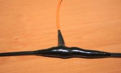
Photo 3. Appearance of the tight connection of the sensor with the PRPPM type cable
Firstly , the sensor wire has a diameter of 0.78 mm. Most of our customers are oriented when installing this system on a low-pair trace-forming material, namely the PRPPM cable, the most common diameter of which is 0.9, sometimes found 0.7. Thus, the connected wires are approximately the same in diameter and are easily joined by any clip (the clip used to connect the wires has a certain tolerance for the variation in the diameters of the cores being interconnected and we fit perfectly into this tolerance).
Secondly, our experts have selected the most optimal of all available technology for splicing wires, providing high tightness and minimum labor costs - cold sealing according to 3M technology known among installers.
Operational tests in the laboratory of OJSC Morion
As soon as we received the first experimental batch of IGD, which suited us in all respects, we organized operational tests of sensors at the Morion Perm plant. Morion is one of the leading factories for the production of communications equipment, the testing laboratories of which are accredited in accordance with the certificate of the Gosstandart of Russia for testing, including third-party products, which we used.
So, in January 2011, IGD sensors successfully passed the “exam” in the Bureau of Reliability and Certification Testing (BINiS) of Morion OJSC. The purpose of the tests, of course, was to check the tightness of the IHD in harsh operating conditions, as well as to determine the range of operating temperatures.
In the presence of developers from Technotronics and Morion’s testing experts, the IGD sensors were checked for several hours: they were completely immersed in water and placed in a thermal chamber, drastically changing the temperature in it and constantly checking the operation of the IGD. IHDs were connected first to the MAX LKS controller , and then to the MiniMAKS . The Tekhnotroniks.SOL software displayed data received from sensors through controllers.
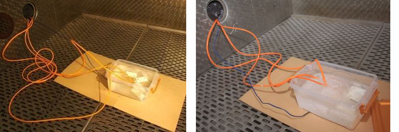
Photo 4, 5. Tests of IHD in a thermal chamber with full immersion in water. The sensor is in water, the sensor is frozen.
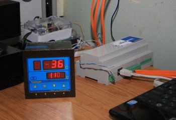
Photo 6. Testing the operation of IHDs located in a thermal chamber at different temperatures. Sensors are connected to the MiniMAKS controller.
After the tests, the experts of Morion OJSC concluded that:
- the recommended temperature range for the operation of the IHD is (-40 ... + 50) ° С. This is quite sufficient for the use of sensors in the outdoor conditions of the Russian climate, in particular for the protection of KKS wells.
- Leak tests, which were carried out when the sensors were completely immersed in water for several hours in the temperature range (-40 ... + 50) ° С, were crowned with success. IHD fully retained its performance. Moreover, the insulation resistance of IGD measured by experts amounted to more than 30,000 megohms, which is 30 times more than the normal resistance of the “native” cable for CCI cable signalmen lying in the wells of the KKS.
All stages and test results are officially recorded in the act and test report.
Certificates, Patents for IPD
 After operational tests, already convinced that the new design of the sensor, it is also a sealing method, a really good solution, we started the process of certification of sensors. And in March 2011, the Technotronics company received a certificate in the GOST R system for IGD sensors as a guarantee of their quality.
 In addition, there are three patents on the IHD. As you already understand, the development lasted two years (2009-2011), and we successively patented our achievements: first the system itself, then the hermetic design of the sensor and, finally, the method of protection against short-circuit of the IHD sensors.
 |  |  |
Operational results
Now, 3 years after we found a solution that suits everyone, a large database of completed projects has been accumulated and there are official reviews of the successful operation of the system. Who cares, please read .
2012 - Intelligent PHOTO-sensor or “ray of light in the dark kingdom”

Photo 7. Intelligent Photo
Sensor (IFD) However, having achieved success, we continued our research, which culminated in the development of the Intelligent Photo Sensor - abbreviated IFD. What is the essence of the sensor?
Any primary converter is all the more effective, the more sharply the environmental conditions to which it (the converter) reacts change. So, it is the illumination in the conditions of “closed hatch / open hatch” that changes most significantly. As it is easy to understand, with a closed hatch inside the well, complete darkness reigns around the clock. Taking advantage of this fact, we focused on a sensor sensitive to the weakest light, without fear of false alarms in the “closed” state. When opening the manhole cover, even at night, the sensor receives background illumination of the external environment, which is always available in urban conditions. And the sensor due to its high sensitivity is triggered. This is the first. And secondly, those who opened the well will try to either steal the cable or lay an unauthorized route. To do both is impossible without the use of flashlights and other lighting fixtures.
Also, the IDF leaves no room for sabotage such as “took it, quickly covered the sensor with a cap - that's all.” The sensor detects and remembers even short-term autopsies. And, of course, it will transmit alarming information to the monitoring center.
Its differences from conventional HDI are a semitransparent case with the effect of dispersion of the received light flux. Well, and of course, the absence of the second half - the usual magnet. And here lies its main advantage. They are REALLY much easier to mount and operate. After all, there are no problems installing the magnet, fitting it to the reed switch, breaking off during impacts and throws, etc. Our users have already rated these benefits.

You can find even more photos of mounted IFDs on our website. Who wants to read the feedback from telecoms about the operation of the IFD-based system, please click here
2012-2013 IFD-R, IGD-R - intelligent sensors that disable a shorted section of the route.
Almost in parallel with the development of Intelligent Photo Sensors, we began work on a modification of the IHD, which, in addition to its main function of tampering, would provide additional features - disabling a shorted section of the track.
The circuit can be short-circuited for two reasons: 1) the closure of the well monitoring sensor itself, or 2) the leaky joint of the sensor with the route.
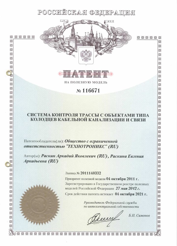
In the case of using IHD, the first option is unlikely. This is due to the circuitry of the IHD sensor: it is constructed in such a way that the risk of shorting inside the sensor itself is minimized. And this fact is officially confirmed by RF Patent No. 116671. Therefore, the most likely reason is the leakage of the junction of the sensor with the track during installation.
Of course, eliminating a short circuit is a solvable task. But it is sometimes extremely difficult to find the place of occurrence of the problem with a parallel connection scheme. Indeed, most often a violation of the tightness of the route does not occur immediately after installation, and it is not easy to find out in which well it was shorted. Wells are located over fairly long distances, often in hard-to-reach places.
Before the development of the IGD-R sensors, the way out of such a situation that we saw was a rather complicated method for finding the damaged area - the half division method. The essence of the method is that in case of damage, first one of the cable connections is disassembled near its middle, then its part farthest from the MAX LKS or MiniMAX module is disconnected and they look to see if the voltage in the cable has increased. If the voltage has increased, then the damage is in the far part, if not increased - in the part closest to the module. Then the procedure is repeated for that part of the loop in which damage was detected, and so on ...
The disadvantages of the method are obvious. Firstly, it is necessary to break a large number of intact, “innocent” compounds. Well, and secondly, the method is quite time-consuming and requires considerable costs in man-hours and, accordingly, “in finance”. In general, such a non-optimal way to identify the place of failure clearly required the creation of an alternative. And we developed the IGD-R sensors .
IGD-R, in addition to protecting wells, performs the function of an insulating kit , that is, it disconnects (forcibly opens) the section of the route following this IGD-R in the event of a short circuit in this section. Disconnection occurs by opening the corresponding electronic keys inside the sensor, hence the prefix "P" in the name of this device.
After the route is opened, the Customer needs to check for leaks only that section of the route that is between this IGD-R and the next. Thus, the IGD-R becomes for the Customer a tool for segmenting the route and in case of damage to the route and the occurrence of a short circuit will indicate a problem place or section. Examples of IGD-R placement on various types of routes, IGD-R connection diagram and many other details can be found in a separate article on this device .
Soon after the development of IGD-R, we, of course, made a similar modification for IFD. Thus, our last device for this direction was developed - the IFD-R sensor.
In summary ...
Now we offer the Customer a choice of 4 types of sensors, which, by the way, are absolutely compatible with each other and can be used in any combination:
- The intelligent reed switch of the IHD is a reed-magnet type sensor that has all of the above advantages.
- The IGD-R Intelligent Reed Sensor is a modification of the IGD sensor, which allows you to specify the section of the route on which a short circuit occurred.
- Intelligent Photo-Sensor IFD - a unique sensor that works on a photo-principle. IFD instantly reacts to the light entering the well when opening even at night.
- Intelligent Photo Sensor IFD-R- This is a modification of the IFD sensor, which allows you to specify the portion of the route on which a short circuit occurred.
All of them work with MAKS LKS or MiniMAKS controllers located on the PBX.
In summary, I want to once again list the advantages of smart sensors :
- Speed: IGD and IGD-R record the opening of the well in 0.1 sec., IPD, IFD-R - in 0.3 sec., The time of data delivery to the dispatch center when using IGD and IGD-R - 1 sec., IPD - 5 sec.
- Immunity to interference, lightning and internal short circuits.
- Targeting: accurate identification of each well in case of opening.
- Efficiency even with a break: a break in one or more sensors of the IHD or IFD does not affect the operation of the remaining sensors.
- Guaranteed delivery of information: even with the simultaneous activation of several sensors, a signal from each of them will come to the dispatch center.
- Operating temperature range: from -40 ° С to + 50 ° С, which corresponds to the operating conditions of KKS wells ..
- Full tightness:
- The sensor electronics board is sealed in a monolithic polyurethane housing;
- Reliable tight connection of the sensor housing and cable;
- A copper pair of wires has 4 levels of moisture protection: polyurethane insulation, water-blocking threads, water-blocking sheath, own insulation of copper conductors.
The cost of sensors IGD, IFD - 1534 p. VAT included.